
A low-light indicator
Operation
The heart of the circuit shown in Figure 1 is a photo-conductive cell, also called a light-dependent resistor (LDR), a device whose resistance changes according to the amount of light falling on it. In bright light, the resistance is low (about 1 kΩ), whereas in the dark, its resistance is very high (up to 10 MΩ). The cell is made from a semiconducting material known as cadmium sulphide (CdS), and is enclosed in a small plastic container. The semiconductor is laid on a flat insulating surface in the form of a small flat ribbon. The ribbon construction gives a good area of surface for a given length of ribbon, and the length of the ribbon is maximised by laying it out in a zig-zag pattern, as can be seen diagrammatically in Figure 2. In the dark, CdS is an insulator; when light falls on it, electrons are released inside the CdS, making it conduct. The more light there is, the more electrons there are, and the resistance falls.
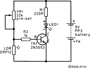

In this circuit, the LDR is connected across the 9 V supply in series with a variable resistor, VR1. In this arrangement, the voltage that exists across the LDR will be determined by the light level. As the light intensity increases, the resistance of the LDR falls, dropping a smaller voltage across it. The reverse happens when the light intensity falls – the voltage across the LDR increases. This voltage is used to drive an npn transistor, TR1, connected as an electronic switch. As the voltage on the base (B) rises, it will reach a point where TR1 will suddenly start to pass current, just as an ordinary switch does when pressed. The current flowing through TR1 also flows through a flashing light-emitting diode (LED), D1 and its series resistor, R1. D1 can be a steadily glowing type, if preferred. If you want to make the circuit switch the LED on at a different ambient light level, adjust VR1.
Construction
The prototype was made on an eight-tag tagboard (Figure 2). The resistors R1 and R2 can be laid on the tagboard for soldering, the rest of the components lying above or to the side of the board. Check the circuit after you have soldered everything on, then connect the battery. The LED should flash if you put your hand over the LDR, and VR1 can be adjusted to vary the point at which the LED lights. The project can be housed in a small plastic box with holes provided for the LDR and LED and an on/off switch if you want one.