
A J-pole aerial for 50 MHz
Basic facts
A feeder must be connected to an aerial at a point where the impedance (AC ‘resistance’) of the aerial closely matches that of the feeder. The difference between the two impedances gives rise to the voltage standing-wave ratio (VSWR), which is unity only when the two impedances are the same. With 50 Ω feeders, the feed point of a half-wave aerial is at the centre, where the aerial impedance is around the same value. At the end of a half-wave aerial, the impedance is high, so it is not a suitable point to connect a 50 Ω feeder.
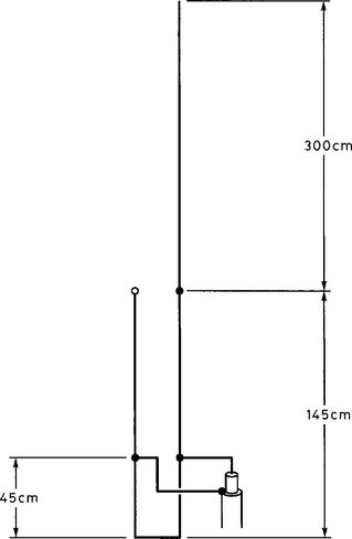
Connection at this point can be effected using an RF transformer. RF transformers act in the same way as ordinary transformers, except that they are much smaller, and usually comprise wires of particular lengths adjacent to each other. Figure 1 is a good starting point. It shows the aerial in its diagrammatic form. Notice that the aerial is in the form of an elongated letter ‘J’; this shape gives rise to its nickname – the J-pole. The quarter-wave RF transformer is the lower ‘U’ section below the half-wave element. At the bottom of the U section, the impedance is zero (this may become clearer later) and at the top of the U section it is high, thus matching the aerial impedance. The coaxial feeder cable is connected part-way up the U section, where the impedance is around 50 Ω.
The practicalities
Figure 2 shows the aerial as constructed. As it is about 4.5 metres high, it may be too high for the average house loft, but is ideal for mounting outside, supported by a non-metallic pole or hung from a tree branch. The upper half-wave section is made from 1.5 mm insulated copper wire, as used in domestic mains wiring. The quarter-wave transformer below the half-wave section is made from 300 Ω balanced line (‘ribbon cable’). The wires at the bottom of the transformer section are stripped of their insulation, twisted and soldered. At the upper end, only one wire of the balanced line is soldered to the bottom of the half-wave section. The other wire of the pair is not connected and is left insulated.
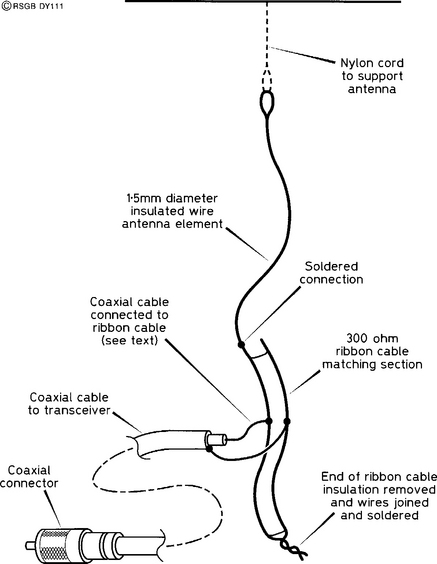
At the feed point of the transformer, the insulation needs to be carefully stripped from the balanced line. You will need a standing-wave meter (VSWR meter) in the coaxial line between your transmitter and the aerial, and you will need to adjust the position of the feed point. 45 cm from the bottom was the best point on the prototype, but this position is dependent upon the immediate surroundings of the aerial, and must be done when the aerial is in its final operating position. Warning: Never make adjustments to the feed point when the transmitter is on. Make a VSWR measurement, switch off, move the feed point, switch on again, make another measurement, and so on. You will need to aim for the lowest VSWR you can – certainly better than 2:1. Having found the best position, wrap all the exposed wires with self-amalgamating tape, to seal them against the ingress of moisture.
How It performs
Figure 3 shows a computer prediction of how the J-pole radiates. It is called a polar diagram, and shows the distribution of your transmitted power when viewed ‘from the end of your garden’. Most of your signal is sent at a fairly small angle to the horizontal; very little signal goes upwards, which is a good thing, of course. This also shows why the J-pole (or any other vertical aerial) should not be called ‘omnidirectional’, which means it radiates in all directions. It is omnidirectional only in the horizontal plane.

Safety
Where you mount your aerial is a matter of personal preference and the restrictions of height and space, but the following safety rules must be applied.
1. Never fix an aerial where it may come into contact with power lines or telephone lines.
2. When climbing a ladder to put up an aerial outside, make sure the ladder is safe and that it is secured.
3. Don’t do this alone. Preferably have someone with you. If this is not possible, make sure someone knows where you are.