
An RF signal probe
The circuit
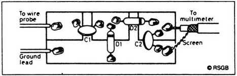
Figure 1 shows the simple circuit diagram. It is almost the same as a common diode rectifier circuit, but with a simple change to make it more sensitive. The circuit is known as a voltage-doubler, and is often found in high-voltage supplies, with beefier capacitors and diodes, of course! Because we are dealing with high frequencies and smaller voltages, the diodes and capacitors can be physically very small. The diode circuit of D1 and D2 rectifies or detects the RF from the probe, and any remaining AC is removed (short-circuited to ground) by C2. This produces, at the output, a constant voltage proportional to the peak-to-peak RF voltage present at the input; the output voltage is fed to an ordinary multimeter (on a voltage range).

Construction
Although the circuit layout is not critical, a description of the prototype is given here for your information. Figure 2 has the details. The components are soldered to square pieces of copper-clad printed-circuit board (PCB) glued to a larger piece of PCB. The larger piece serves as a ground connection. Use a stiff copper wire as the probe, and an insulated flexible wire with a crocodile clip to connect the probe to the ground of the circuit under test.
Cut a piece of plain PCB, 30 mm by 45 mm and another of 15 mm by 45 mm. Cut the smaller piece into three measuring about 15 mm square. Stick the three small pieces to the larger piece, ensuring that there are small gaps between each, as Figure 2 shows. Solder the components in place. The connection to the multimeter should be thin coaxial cable or screened microphone cable. If you use unscreened cable, there may be RF pickup here which can lead to false readings.
Simple to use
Using the probe is simple. Connect it to the multimeter and set the meter to around 10 V DC – you may need to reduce this, depending upon the magnitude of the RF voltage you are trying to measure. Hold the probe by its base, being careful not to touch any of the components. Connect the croc clip to a ground point on the circuit and touch the probe on the circuit point to be tested. If an RF signal is present, there should be a reading on the multimeter. That’s all there is to it!