
A resistive SWR indicator
How do you know when this matching has been achieved? The most usual way is to use a standing-wave ratio (SWR) indicator. If the impedance of the aerial does not match that of the transmitter output, some of your transmitter power (also known as the forward power) is reflected back along the aerial feeder and back into the transmitter, where it causes excess heating. The forward and reflected waves interact along the feeder to produce a wave whose position remains constant, and which is therefore called a standing wave or a stationary wave. An SWR meter simply indicates forward power and reflected power, and adjustments are made to your ATU until the reflected power is as small as possible (ideally zero, of course). If there is no reflected power then, by a process of elimination, all your forward power is reaching the aerial!
Sampling the RF
Whatever type of SWR indicator you use, it must use some sort of sampling circuit to pick up the forward and reflected waves. The project A standing-wave indicator for HF, elsewhere in this book, uses a toroidal transformer to separate the readings for the forward and reverse waves. This design differs in that it measures the voltages across resistors through which the RF current is passing. Its advantages are:
(a) it uses cheap parts – four resistors, two capacitors and a diode, together with a rotary switch, a surplus meter, a preset potentiometer and two sockets;
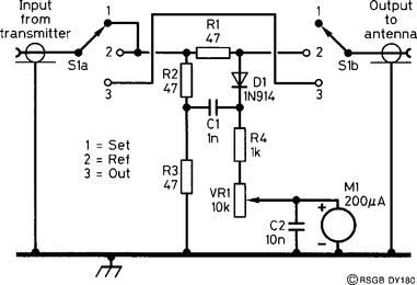
(b) within this SWR indicator, there is always a resistive path for the RF current from the transmitter, formed by R1, R2 and R3; this can prevent damage to simpler home-made transmitters, which may be damaged during adjustment of the ATU when using more conventional SWR indicators.
The only disadvantage of this form of indicator is that it must be switched out of circuit once the ATU has been adjusted for a particular band.
Construction
The SWR indicator is very simple to build, as most of the components can be mounted on the back of the 3-way rotary switch. This is shown in Figure 1. The switch is a 4-pole, 3-way rotary type, of which only two poles are used.
Because the other switch contacts are not being used, they can be employed as support tags for other components. The ground wires are all soldered on to the metal frame of the switch. If your switch frame is of all-plastic construction, then a 12 SWG copper wire run around the switch will make a good earth connection to the metal case for the leads shown in Figure 1. The preset potentiometer used to control the sensitivity of the circuit can be mounted directly on the meter tag.
Resistors R1, R2 and R3 handle the RF power during the tuning-up process. If you have them, use 1 watt resistors; otherwise, you can use two 100 ohm half-watt resistors in parallel for each of R1, R2 and R3. The meter, M1, can be any DC type of sensitivity around 200 μA.
In use
First, find a clear frequency, and without the indicator in circuit, check that the frequency really is clear by asking and identifying yourself. If it is, connect the indicator between the transmitter and the ATU which, in turn, is connected to your aerial. Turn SW1 to the SET position and key the transmitter. Adjust VR1 until the meter reads full scale. Switch off the transmitter. Turn SW1 to the REF position and key the transmitter again. Adjust the ATU until the lowest reading is obtained on the meter. Switch off the transmitter. For the chosen frequency, you have adjusted your ATU for minimum reflected power and hence the lowest SWR. You will need to repeat the process when you change bands, and possibly when you change frequency within the same band. Switching SW1 to the OUT position, you are ready to transmit. You may have noticed that it is good practice to switch the transmitter off when operating SW1. Get into that habit!