Project 6 – Interactive LED Chase Effect
Leave your circuit board intact from Project 5. You're just going to add a potentiometer to this circuit, which will allow you to change the speed of the lights while the code is running.
Parts Required
All of the parts for Project 5 plus....
| 4.7KΩ Rotary Potentiometer | 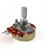 |
Connect It Up
First, make sure your Arduino is powered off by unplugging it from the USB cable. Now, add the potentiometer to the circuit so it is connected as shown in Figure 3-2 with the left leg going to the 5v on the Arduino, the middle leg going to Analog Pin 2, and the right leg going to ground.
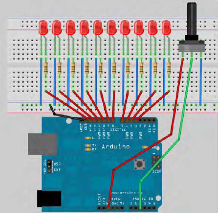
Figure 3-2. The circuit for Project 6 – Interactive LED Chase Effect (see insert for color version)
Enter The Code
Open up your Arduino IDE and type in the code from Listing 3-2.
Listing 3-2. Code for Project 6
byte ledPin[] = {4, 5, 6, 7, 8, 9, 10, 11, 12, 13};    // Create array for LED pins

int ledDelay; // delay between changes

int direction = 1;

int currentLED = 0;

unsigned long changeTime;

int potPin = 2;    // select the input pin for the potentiometer


void setup() {
for (int x=0; x<10; x++) {   // set all pins to output

                pinMode(ledPin[x], OUTPUT); }

        changeTime = millis();

}


void loop() {
ledDelay = analogRead(potPin); // read the value from the pot

        if ((millis() - changeTime) > ledDelay) {      // if it has been ledDelay ms since

                                                          last change

                changeLED();

                changeTime = millis();

        }

}


void changeLED() {

        for (int x=0; x<10; x++) {   // turn off all LED's

                digitalWrite(ledPin[x], LOW);

        }

        digitalWrite(ledPin[currentLED], HIGH); // turn on the current LED

        currentLED += direction; // increment by the direction value

        // change direction if we reach the end

        if (currentLED == 9) {direction = -1;}

        if (currentLED == 0) {direction = 1;}

}
When you verify and upload your code, you should see the lit LED appear to bounce back and forth between each end of the string of lights as before. But, by turning the knob of the potentiometer, you will change the value of ledDelay and speed up or slow down the effect.
Let's take a look at how this works and find out what a potentiometer is.
Project 6 – Interactive LED Chase Effect – Code Overview
The code for this Project is almost identical to the previous project. You have simply added a potentiometer to your hardware and the code additions enable it to read the values from the potentiometer and use them to adjust the speed of the LED chase effect.
You first declare a variable for the potentiometer pin
int potPin = 2;
because your potentiometer is connected to Analog Pin 2. To read the value from an analog pin, you use the analogRead command. The Arduino has six analog input/outputs with a 10-bit analog to digital convertor (I will discuss bits later). This means the analog pin can read in voltages between 0 to 5 volts in integer values between 0 (0 volts) and 1,023 (5 volts). This gives a resolution of 5 volts / 1024 units or 0.0049 volts (4.9mV) per unit.
Set your delay using the potentiometer so that you can use the direct values read in from the pin to adjust the delay between 0 and 1023 milliseconds (or just over 1 second). You do this by directly reading the value of the potentiometer pin into ledDelay. Notice that you don't need to set an analog pin to be an input or output (unlike with a digital pin):
ledDelay = analogRead(potPin);
This is done during your main loop and therefore it is constantly being read and adjusted. By turning the knob, you can adjust the delay value between 0 and 1023 milliseconds (or just over a second) and thus have full control over the speed of the effect.
Let's find out what a potentiometer is and how it works.
Project 6 – Interactive LED Chase Effect – Hardware Overview
The only additional piece of hardware used in this project is the 4K7 (4700Ω) potentiometer.
You know how resistors work. Well, the potentiometer is simply an adjustable resistor with a range from 0 to a set value (written on the side of the pot). In this project, you're using a 4K7 (4,700Ω) potentiometer, which means its range is from 0 to 4700 Ohms.
The potentiometer has three legs. By connecting just two legs, the potentiometer becomes a variable resistor. By connecting all three legs and applying a voltage across it, the pot becomes a voltage divider. The latter is how you going to use it in your circuit. One side is connected to ground, the other to 5v, and the center leg to your analog pin. By adjusting the knob, a voltage between 0 and 5v will be leaked from the center pin; you can read the value of that voltage on Analog Pin 2 and use it to change the delay rate of the light effect.
The potentiometer can be very useful in providing a means of adjusting a value from 0 to a set amount, e.g. the volume of a radio or the brightness of a lamp. In fact, dimmer switches for your home lamps are a kind of potentiometer.
EXERCISES