
15
Polynomial-Based Image Sharing
Shiuh-Jeng Wang, Chen-Hsing Yang and Yu-Ting Chen
Central Police University, Taiwan
National Pingtung University of Education, Taiwan
CONTENTS
15.1 Introduction
The concept of secret sharing comes from the method of secret key management and was first seen in the following works [1, 7]. The secret's owner wants to share the secret with other participants, but no participants can obtain the secret alone. When some of the participants work together, the secret is then revealed. From a technical viewpoint, this secret sharing scheme may also be referred to as the (t, n)-threshold, where t denotes the threshold value that will reveal the secret and n is the total number of holding shadows. In this method, when a secret is given, it must be divided into n shadows and it is then reconstructed by t or more shadows, possessed by the shadow holders; no information can be conjectured by fewer than t shadows. In the wake of this cryptographic application proposal, many related methods were further proposed to enrich secret sharing diversity in both theoretical and practical arenas [4, 6, 8, 12].
Visual security was proposed by Naor and Shamir [6] in 1994, where an image could be reconstructed by superimposing two shares. The shares issued in this scheme are made up of random binary patterns. The target secret, recognized by the human visual system, is finally stacked by the (t, n)-threshold scheme. One of the main advantages, in this scheme, is that it does not require complicated computations, which traditional numeric cipher-text in secret decryption does, while the sizes of the enlarged shares, and target secrets are left the same. Thien and Lin [8] proposed an applied secret image scheme for image embedding to improve upon Naor and Shamir's method. The concealment of a secret image avoids cipher-based attacks on the basis of stego-image imperceptibility. In 2006, Horng et al. uncovered another way to cheat the (t, n)-threshold under visual cryptography (VC) applications [3]. In their proposal, a scenario was successfully put forward showing that shareholders were able to collaborate with each other by sending fake shares to other shareholders. Accordingly, the final target secret image was different from the genuine one, corrupting the secret sharing system.
Steganography is a kind of data hiding technique that provides another method of security protection for digital image data. The purpose of steganography is to embed secret data in preselected meaningful images, called cover images, with people being visually unaware of the secret's existence. Numerous schemes have been developed to achieve successful data hiding [2, 5]. To prevent the fake stego-image from the dishonest participants, Lin and Tsai [4] authored an authentication-based steganography study, where their detection technique tested whether the offered shares were genuine or not. In their scheme, parity checks were applied to prevent the modified shares from malicious attacks. Later on, in 2007, Yang et al. [12] enhanced the mechanism of Lin and Tsai by proposing a revised scheme in which more detailed fake shares were created so that they would be detected by those malicious shareholders in the target secret image (t, n)-threshold system, thus acting as a deterrent.
In 2008, Wang et al. [10] took advantage of the CRC (Cyclic Redundant Code) in conjunction with the hash function to make authentication-based steganography more robust, in order to prevent the attacks of fake share offerings. In addition to making it more robust, both the capacity and the image quality remain comparable to the scheme suggested by the scheme in [12]. In this chapter, we introduce the polynomial-based image sharing scheme by reviewing some preliminaries and related works and depicting Wang et al.'s approach. Moreover, some improvements of Wang et al.'s approach are proposed in this chapter.
The presentation of this chapter is organized as follows. In Section 15.2, the concept of the polynomial-based sharing scheme is introduced. In Section 15.3, we introduce some preliminaries and related works about the polynomial-based image sharing scheme. Wang et al.'s scheme and its improvements are presented in Section 15.4. Observations and experiments of benchmark images are presented and discussed in Section 15.5. Finally, conclusions are offered in Section 15.6.
15.2 Polynomial-Based Sharing Scheme
15.2.1 Shamir's Secret Sharing Scheme
A (t, n)-threshold scheme is a method of sharing a secret among n participants such that any subset consisting of t participants can reconstruct the secret, but no subset of smaller size can reconstruct the secret. The first method was provided in 1979 by Shamir [7] and is known as Shamir's secret sharing scheme. In the initial state, a dealer chooses a large prime number p, and makes p public. The following calculation is performed on Zp: A secret, s ∈ Zp exists, so the dealer randomly generates a (t-1)th degree polynomial, in Zq:
where q(0) = s is the secret. The dealer distributes the shadow, yi ≡ q(xi)(mod p) to node Pi, where xi is the ID number for Pi.
Suppose that t participants get together to reconstruct the polynomial. Also, assume that their pairs are (x1,y1), (x2,y2), ⋯, (xt,yt). The polynomial q(x) can be reconstructed by solving the following equation:
The equation has a unique solution if the determinant of the matrix is nonzero mod p. It can be shown that the determinant of the matrix is nonzero mod p if all xi, i = 1, 2,⋯, t, are different. After the polynomial is reconstructed, the secret s is obtained by the output of q(0).
15.2.2 Lagrange Interpolation Scheme
An efficient method to obtain the sharing polynomial f is to use the Lagrange interpolation. Assume that the pairs (x1, y1), (x2, y2),⋯, (xt, yt) are used to reconstruct the polynomial q(x). For k = 1, 2,⋯, t, let
We know that
Then, the Lagrange interpolation polynomial is formed as follows:
Because yi ≡ q′(xi)(modp) for i = 1, 2,⋯, t and q′(x) has degree t − 1, q′(x) is equal to the polynomial q(x). Finally, the secret s can be obtained by evaluating q(x) at x = 0. That is,
In fact, all coefficients in q(x) can be seen as secrets. We show an example for the Lagrange interpolation polynomial.
Example 1.
Take a (2, 4)-threshold scheme. In the share generation phase, assume that the pixels of the target secret image S indexed in order of left-to-right and top-to-down is Si, I = 0, 1, 2, ⋯, n. The first two pixels, for instance, S0 = 100 and S1 = 200 are set in this case. First of all, a polynomial of q(x) = 200x + 100 mod 251 is given according to the
Following up the result, the first two pixels of the target secret image, S0 = 100 and S1 = 200 are obtained from the coefficients of q′(x) = 200x + 100 mod251.
15.3 Preliminaries and Related Works
15.3.1 Thien-Lin Scheme
The (t, n)-threshold scheme in visual cryptography was proposed by Naor and Shamir [6], where the target secret (image) could only be recognized by the human eye if there were exactly t or more than t share-images stacked. However, the share-images generated could only reveal one target secret. When there are more than 2 target secrets, the numbers of share-images required, increases. As a result, the occupied share-images, held by participants, also increase. Inspired by these observations, Thien and Lin (Thien-Lin scheme) [8] proposed a specific method to accommodate a higher number of share-images, with the normal storage requirements, using LaGrange polynomial construction. In this method, there are a total of n share-images, with each of them being only
15.3.2 Lin-Tsai Scheme
In [4], Lin and Tsai (Lin-Tsai scheme) proposed a scheme of sharing image, where the requirements of capacity and detecting ability are further considered when compared to the study of [8]. Similarly, a polynomial of

FIGURE 408.15
The format of Bij, where xi, wi, vi, and ui are represented as binary pattern.
Notations:
q(x): The (t − 1)-degree polynomial of q(x) = (a0 + a1x + a2x2 + … + at−ixt−1) mod p, where p = 251.
S : The target secret image with the size of m × m. The pixel Si ∈ [0, 250] in S, 1≤ i ≤ m2. It is caught by up-to-down and left-to-right in order.
Ij: The jth cover image with the size of 2m× 2m pixels. There are m2 blocks,
Îj: The jth stego-image with the size of 2m × 2m. There are m2 blocks,
bi: Generate a random bit-string with the form of
The procedure to generate the stego-image, named as Proc-Lin-Tsai, is briefly given in the following:
Procedure Proc-Lin-Tsai
Input: S, Ij, j = 1, 2,⋯, n.
Output: I, j = 1, 2, •⋯, n.
Step 1. Generate the random bit string
Step 2. Set a0=Si, i ∈ [1, m2]. For each Si chooses a (t−1)-degree polynomial q(x) = (a0 + a1x + a2x2 + •⋯ + ai−1xi−1) mod p, where randomly choose t-1 value a1 , a2 ,⋯, ai− 1 under the modulo p. Calculate yi = qi(xi), where xi is obtained and defined from xi in the Ij and represent yi as the bit string with the form of yi = (yi1, yi2, ⋯ , yi8).
Step 3. Generate the stego-block,
ŵi = (wi1; wi2; ⋯ ; wi5, b′i, yi1; yi2),
and ûi =(ui1, ui2, ⋯ , ui5, yi6, yi7, yi8),
where
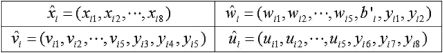
FIGURE 15.2
The format of stego-block
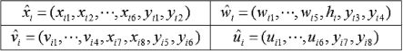
FIGURE 15.3
Stego-block
Step 4. Collect
15.3.3 Yang et al.'s Scheme
As observed from the Lin-Tsai scheme, the fake shares can be easily made by the manner of fixing the parity bit
15.3.4 Inverted Pattern LSB Scheme
In order to conceal the existence of shadow data, steganographic methods are used to keep the shadows imperceptible. The steganographic method is a kind of data hiding technique that embeds secret data in preselected meaningful images, called cover images, with people being visually unaware of the secret's existence. One common technique to achieve the data hiding is the LSB-based approach, in which secret data are embedded by directly replacing the least significant bits (LSBs) with equal bits of the secret for each pixel. Moreover, some papers applied various strategies to improving the quality of stego-images generated by LSB-based approaches. In 2008, Yang [11] proposed an Inverted-Pattern-LSB information hiding algorithm (IPLA for short) to further highlight the quality of the stego-image. His method combines the idea of processing secret messages before embedded and processing the stego-image after embedding. Before embedding, the secret is transformed into a suitable format so as to benefit the next embedding step. Moreover, the bits that are used to record the transformation are the critical key in the course of the secret revelation. The IPLA algorithm is shown below, which was applied in Wang et al.'s scheme.
Inverted-Pattern-LSB Algorithm (H, S, k, n)
Input: A cover image H and a secret string S for k-bit LSB substitution, z is the number of sections.
Output: A stego-image and an inverted pattern P.
Step 1. Partition both H and S into z sections evenly. Let H = H0, H1, ⋯, Hz-1, S=S0,S1,⋯,Sz-1 and R=R0,R1,⋯Rz-1, where R is the replaced string of H. Also, let the inverted pattern P = p0,p1, ⋯, pz-1, where pi is a bit, for i = 0,1, ⋯, z −1.
Step 2. For i = 0 to z − 1
If
Then pi =0
Else pi = 1
Step 3. For i = 0 to z − 1
If pi =0
Then Embed Si into Hi
Else embed Si into Hi
Step 4. Return the inverted pattern P.
15.3.5 Scalable Secret Image Sharing
The conventional secret image sharing (SIS) scheme, such as the Thien-Lin scheme [8], only has the threshold property that recovers either the entire image or nothing. For the ( t, n)-SIS scheme, the target secret image could only be reconstructed by only t or more than t qualified participants. This limits its possible applications. Recently, Wang and Shyu recommended adding the scalable decoding capability (the scalability) into the threshold scheme [9]. The so-called scalability is that the amount of secret information is proportional to the number of shadows used in reconstruction. Wang and Shyu constructed a polynomial based (2, n) scalable SIS (SSIS) scheme, which not only had the threshold property but also the scalability. The clarity of an image in [9] is measured in terms of three modes: the multisecret mode (spatially partitioning the target image into disjoint subimages), the priority mode (dividing the target image according to the bitplanes), and the progressive mode (combining the multisecret mode and the priority mode). To extend Wang and Shyu's (2, n)-SSIS scheme, Yang and Huang proposed (t, n)-SSIS schemes where a qualified set of participants consists of any t participants [13]. Two approaches were proposed for a general construction for any t, 2 ≤ t ≤ n. For t = 2, Approach 1 has the lesser shadow size than Wang and Shyu's (2, n)-SSIS scheme, and Approach 2 is reduced to Wang and Shyu's (2, n)-SSIS scheme. The following is the shadow constructing algorithm of their Approach 1.
Shadow Constructing Algorithm
Input: a secret image O.
Output: n shadows Si, i = 1, 2,⋯, n.
Step 1. Divide image O into
Step 2. For every image Ox, use a polynomial-based (t,t)-SIS scheme to create t subshadows
Step 3. Set S1 = S2 = ⋯= Sn = Φ.
Step 4. Choose a binary matrix Bn,t = [bi,j].
Step 5. For j = 1 to
Set y =1;
For i = 1 to n
If bi,j = 1 then
else
Step 6.
The binary matrix Bnt = [bi,j] is a
The corresponding matrix
Then, four shadows S1 , S2, S3, and S4 are generated as follows.
15.4 Wang et al.'s Scheme
In this section, we describe in detail Wang et al.'s scheme [10] to introduce the standard method of polynomial-based image sharing. Some notations in Wang et al.'s scheme have been trimmed for easy description. Also, the Galois Field GF(28) operations are applied to their scheme such that the all gray-level values 0~255 can be completely represented. Therefore, the secret image is completely lossless. The detailed approaches in Wang et al.'s scheme are introduced in the following subsections.
15.4.1 Secret Image Sharing
Based on the study in the literature [8], a secret image sharing technique was applied in our scheme. In their proposal, the size of shadows could be dramatically reduced, with n shares being embedded into n different host images to avoid the attention of hackers. However, if malicious participants deliver fake stego-images, the receivers may recover a fake secret image, thus misleading those participating in the secret sharing scheme, due to poor detection. Thus, yet another secret sharing function was invented, that we also applied in our proposal, using detection authentication to enhance security. Below, a revised algorithm is presented to achieve both high capacity and extended applications, where participants can recover two or more secret images from a stego-image. The notations for the Revised Algorithm of High-Capacity and Applications (RAHA for short) are given prior to all the steps shown.
Notations:
S: The target secret image with size m × m.
t: More than or equal to t shadows possessed by the participants that can recover the target secret image.
n: The number of participants.
St: Each pixel of the target secret image S, i = 1, 2, ⋯, m2.
Bi,j: The g th block (size of 1 × 8) in the j th cover image, where j = 1, 2,⋯, n and g = 1, 2,
fj: The feature value of the jth stego-image (or the jth cover image) when the block
p: 256 for the Galois Field GF(28).
Revised Algorithm of High-Capacity and Applications (RAHA) Part I: Aim at the high capacity approaching:
For g−1, 2, ⋯,
Step 1. Generate the polynomial qg (x) of t − 1 degrees as follows:
q(x) = (a0 +a1x + a1x2 + ⋯ + ai-1xi-1)
where a0 = Si, a1 = Si + 1, ⋯ , at−1=Si+t−1, i = (g − 1)t, and all operations are over the Galois Field GF(28).
Step 2. Get block Bg, j• from the jth cover image. Set fj as the feature value of block Bg,j, j = 1, 2,⋯, n.
Step 3. Compute
Step 4. Assign each

FIGURE 414.15
Demonstration of steps in RAHA.
The steps stated in RAHA are also demonstrated in Figure 15.4.
Part II. Aim at the recovery of the original secret image.
Step 1. Collect at least t shadows among n shadows. Renumber t of them as 1, 2, …, t in order.
For g = 1, 2, ⋯ ,
Step 2. Chose the t feature value fj, j = 1 , 2, ⋯, t forms the collected stegoimages.
Step 3. Let xj = fj, for j = 1, 2,⋯, t. Reconstruct qg (x)by using the pair of (xj,
Step 4. Restore t pixels of the secret image from the t coefficients in the polynomial function qg (x) = (a0 + a1x +⋯+ at−1xt−1 ).
15.4.2 Set-Up Authentication
In Thien and Lin's proposal [8], the size of shadows could be dramatically reduced, with n shares being embedded into n different host images to avoid the attention of hackers. However, if malicious participants deliver fake stegoimages, the receivers may recover a fake secret image, thus misleading those participating in the secret sharing scheme, due to poor detection. Thus, yet another secret sharing function was invented in Wang et al.'s scheme to enhance security by introducing an authentication procedure. The CRC (Cyclic Redundancy Code Check) and hash function are therefore considered to prevent the fake shares from the malicious participants who offer in the course of revealing the secret image, where the CRC is implemented by CRC-8. Based on the CRC adoption, once the participants receive the stego-image, the CRC will be launched to check all pixels in the stego-image prior to the reconstruction of secret image. The CRC-based detecting authentication procedure for each block in the stego-image is presented as follows:
Step 1. Let G(x) be the polynomial generator. Set/Reset the authentication code of CRC-8 as Cg = (cg1, cg2, ⋯, cg8) = "00000000," g = 1, 2, ⋯,
Step 2. Obtain remainder polynomial R(x) = B(x)modG(x).
Step 3. Assign the coefficient of R(x) to Cg.
Step 4. Store Cg to the block
Step 5. Compare the R(x) and Cg. If the result is the same, the block
Example 2.
Consider a gray-level block with a size of 8 pixels. Assume that the
15.4.3 Main Algorithms
In this subsection, Wang et al.'s main algorithm, Secret Embedding and Detecting Algorithm (SEDA for short) and Target Secret Image Recovery Algorithm (TSIRA) are presented. More notations are given together with the above-mentioned notations as follows.
Notations:
Ij: The jth cover image with the size 2m × 2m pixels.
Ij The jth stego-image with the size of 2m × 2m.
K : A secret key K used in the hash function.
Secret Embedding and Detecting Algorithm: The SEDA aims at the secret embedding and detecting authentication.
Input: S, Ij, j = 1, 2, ⋯, n, k.
Output: Îj, j = 1 , 2, ⋯, n.
Step 1. Get the distinct feature-value fj = (x11, x12, x13, x14, x21, x22, x23, x24) from Bg, j of the cover image Ij, where j = 1, 2,⋯ , n. If fi is equal to one of the feature-values f1 , f2, ⋯, fj-1, then keep looking for the next pair of pixels in block Bg, j.
Step 2. Call RAHA to compute
Step 3. Apply IPLA to generate a pattern-string. Inspecting each block
Step 4. According to CRC-based detecting authentication procedure, generate
Step 5. Arrange all pixels in block
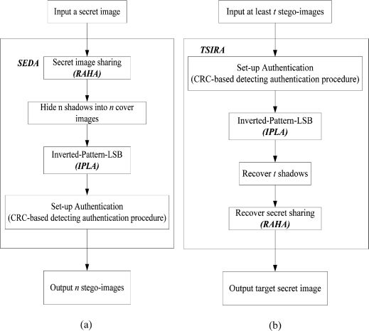
FIGURE 15.5
A secret sharing system with target secret embedding of high capacity and detection authentication: (a) Flowchart of target secret embedding procedures; (b) Recovery of target secret forms the stego-images in our secret sharing systems.
Step 6. Construct Îj by gaining
Target Secret Image Recovery Algorithm: The TSIRA aims at the recovery of the original secret image.
Input: A set of at least t stego-images and a secret key K.
Output: A target secret image S if all the stego-images are authenticated to be genuine.
Step 1. Renumber t of the inputted stego-images as Îj, j = 1, 2,⋯, t, in order.
Step 2. Use a secret key K and call the CRC-based detecting authentication procedure in the stego-image Îj. If the comparison for the authentication code Cg is then correct, proceed to the next step, otherwise, a fake stego-image is detected.
Step 3. For each
Step 4. Pick up fj and calculate
Step 5. Call RAHA to recover the polynomial with the t pair of
Step 6. Combine all Si in order to reveal the target secret image S.
Wang et al.'s scheme with the proposed algorithms to fulfill the sharing system with the target secret high capacity and detection authentication are sketched as shown in Figure 15.5.
15.5 Experimental Results
Capacity and detecting authentication procedure are presented and discussed in this section via the observations of experiments for benchmark images. Two samples of (2, 4)-threshold and (4, 6)-threshold schemes are taken into consideration, in order to highlight the contributions made by Wang et al.'s proposed method.
15.5.1 Fidelity Analysis
The target secret image is shown as Figure 15.6 (a). The benchmarks of the cover images are Bridge, Butterfly, Toys, and Airplane, respectively, shown in Figures 15.6 (b) − (e). The size of the target secret image is
Now considering another case, the (4, 6)-threshold scheme is used to embed two target secret images, as shown in Figure 15.7 (a) and (b). The six cover images are shown in Figure 15.7 (c) − (h). The size of each target secret image is
As seen below, colored benchmark images are further considered to the embedding system via SEDA. The target secret image is shown in Figure 15.8 (a). These show the experimental results, using full color cover images. The PSNR measurements were evaluated as 43.39, 43.12, 43.41, and 43.40, respectively, for the discriminations between the cover and stego-images, shown in Figures 15.8 (b)-(e) and (b′)-(e′). The comparisons, between the PSNR measurements in Wang et al.'s and some other studies are presented in Table 15.3. The (2, 4)-threshold scheme was applied, in this case, among the stego-images shown in Figures 15.8 (b′)-(e′). The target secret image can be seen to be totally revealed, and identical to the original, shown in Figure 15.8(a).
Table 15.1 PSNR comparisons for past schemes and our scheme.
| Bridge | Butterfly | Toys | Airplane | |
| Lin-Tsai-scheme (PSNR) | 39.11 | 39.13 | 39.23 | 39.16 |
| Yang et al. scheme (PSNR) | 41.61 | 41.46 | 41.44 | 41.69 |
| Wang et al. scheme (PSNR) | 43.42 | 43.43 | 43.41 | 43.44 |
15.5.2 Evaluating Authentication
In this section, the detection ability of the Lin-Tsai scheme, Yang et al.'s scheme and Wang et al.'s are discussed. These are then compared, as shown in Figures 15.9-15.11.
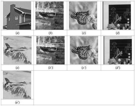
FIGURE 420.15
(a) the target secret images; (b)-(e) the four cover-images; (c′)-(h′) the four stego-images.
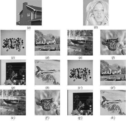
FIGURE 15.7
(a) and (b) the target secret images; (c)–(h) the four cover-images; (c′)–(h′) the four stego-images.
Table 15.2 PSNR measurements when embedding the two target secret images in Figure 15.5 (a) and (b) comparisons for past schemes and our scheme.
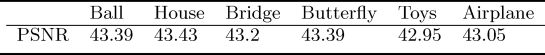
Table 15.3 PSNR comparisons with the Lin-Tsai scheme.
| Milk | Tiffany | Baboon | Airplane | |
| Lin-Tsai-scheme | 39.07 | 39.08 | 39.08 | 39.07 |
| Wang et al. scheme | 43.39 | 43.12 | 43.41 | 43.40 |

FIGURE 15.8
(a) the target images; (b)–(e) the four cover images; (b′)–(e′) the four stego-images.

FIGURE 15.9
Minor bit adjustments in the stego-image of " airplane" (a) Lin-Tsai scheme, (b) Yang et al. scheme, and (c) our scheme.
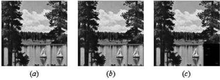
FIGURE 422.15
Partial area adjustments in the stego-images of "sailboat." (a) Lin-Tsai scheme, (b) Yang et al.'s scheme, and (c) our scheme.
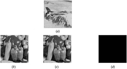
FIGURE 15.11
Replacement of "airplane" stego-image with "pepper." (a) original stego-image of "Airplane", (b) replaced by "pepper" Lin-Tsai scheme, (c) replaced by "pepper" in Yang et al.'s scheme, and (c) detected in our scheme.
Case I. Minor bit adjustments in the stego-images, with results compared in Figure 15.9.
Case II. Partial area adjustment of a fake stego-image that can succeed the fake scenarios in [4, 12], but this case is blocked in Wang et al.'s scheme, as shown in Figure 15.10.
Case III. Replacement of a fake stego-image that was visually imperceptible was detected in Wang et al.'s , shown in Figure 15.11. As observed in Figures 15.9–15.11, the three cases not detected by the schemes in [4, 12] were easily made out when Wang et al.'s was applied. The probability of passing a fake stego-image, in the scheme of Yang et al. [12], was
Table 15.4 PSNR comparisons with the Lin-Tsai scheme.
| High capacity | Techniques used in authentications | Probability of cheating (Numerical analysis) | |
| Thien-Lin scheme [8] | YES | N/A | N/A |
| Lin-Tsai scheme [4] | N/A | Parity bit check | N/A |
| Yang et al. scheme [12] | N/A | Hash Function | (1/2)m2 |
| Wang et al. scheme [10] | YES | CRC and Hash fuction | (1/2)4m2 |
15.6 Conclusions
In this chapter, we introduce some polynomial-based image sharing schemes as well as our proposed scheme. These image sharing schemes are based on the (t, n)-threshold scheme to share the secret image to n participants. Sometimes, some authentication approaches and steganographic approaches were applied. Algorithms, such as IPLA, RAHA, SEDA, and TSIRA, were incorporated into our scheme; the RAHA and IPLA were applied [8, 11], aiming to guarantee higher capacity, and SEDA and TSIRA were used to enable the robust authentication requirement, to reveal the original target secret image. Compared to some other studies [4, 8, 12], Wang et al.'s scheme behaved better in the terms of capacity with secret embedding in a stego-image and in detection/authentication to block offers of fake shares.
Bibliography
[1] G. R. Blakley. Safeguarding cryptographic keys. In Proceedings of the National Computer Conference, volume 48, pages 313–317. AFIPS Press, 1979.
[2] C.C., Chang, C.L. Lin, and H. Chou. Perfect hashing schemes for mining traversal patterns. Fundamenta Informaticae, 70:185–202, November 2005.
[3] G. Horng, T.H. Chen, and D.S. Tsai. Cheating in visual cryptography. In Designs, Codes and Cryptography, volume 38, pages 219–236. Kluwer Academic Publishers, 2006.
[4] C.C. Lin and W.H. Tsai. Secret image sharing with steganography authentication. In The Journal of Systems Software, volume 24, pages 405–414, 2004.
[5] S.P. Mohanty and B.K. Bhargava. Invisible watermarking based on creation and robust insertion-extraction of image adaptive watermarks. In Transactions on Multimedia Computing, Communications, and Applications, volume 5 (12), pages 612–613, 1979.
[6] M. Naor and A. Shamir. Visual cryptography. In EUROCRYPT 94, Springer-Verlag Berlin, volume LNCS 950, pages 1–12, 1995.
[7] A. Shamir. How to share a secret. Communication of the ACM, 22:612– 613, November 1979.
[8] C. C. Thien and J. C. Lin. Secret image sharing. In Computers & Graphics, volume 26, pages 765–770, 2002.
[9] R.Z. Wang and S.J. Shyu. Scalable secret image sharing. Image Commun., 22:363–373, April 2007.
[10] S.J. Wang, I.S. Lin, Y.L. Hsieh, and C.Y. Weng. Secret sharing systems with authentication-based steganography. In Proceedings of the 2008 International Conference on Intelligent Information Hiding and Multimedia Signal Processing, IIH-MSP '08, pages 1146–1149, Washington, DC, USA, 2008. IEEE Computer Society.
[11] C.H. Yang. Inverted pattern approach to improve image quality of information hiding by LSB substitution. Pattern Recognition, 41:2674–2683, August 2008.
[12] C.N. Yang, T.S. Chen, K. H. Yu, and C.C. Wang. Improvements of image sharing with steganography and authentication. Journal of Systems and Software, 80:1070–1076, July 2007.
[13] C.N. Yang and S.M. Huang. Constructions and properties of k out of n scalable secret image sharing. Optics Communications, 283((9):1750–1762, 2010.