
2 Classifications and Applications of LEMs
Linear electromagnetic machines (LEMs) develop electromagnetic forces based on Faraday’s and Ampere’s laws, as described in Chapter 1, and produce directly linear motion. Linear motion may be either progressive (Figure 2.1a) or oscillatory (Figure 2.1b) [1–4]. Linear progressive motion even when experiencing back and forth, but nonperiodic, operation modes leads to LEMs whose topology differ (in general) from that of linear oscillatory machines (LOMs). The linear oscillatory motion takes place in general at resonance—when mechanical eigenfrequency equals the electrical frequency—to secure high efficiency in the presence of a strong springlike force (mechanical or even magnetic) [5].
In general, the progressive motion LEMs are three-phase ac devices that operate in brushless configurations, while LOMs are typically single-phase ac devices.
The progressive motion LEMs operate at variable voltage and frequency to vary speed at high efficiency for wide speed control ranges. On the contrary, LOMs operate in general at resonant (fixed) frequency and variable voltage. Close-loop position control may be applied for both LEMs and LOMs. A slight variation of frequency in LOMs may be needed to adjust the resonance frequency with the mechanical (magnetic) springs rigidity variation due to temperature and (or) aging and thus secure high frequency over the entire device life (10 years or more). Linear progressive motion machines may be classified by principle into
Linear induction machines (with sinusoidal current control)
Linear synchronous (brushless ac) machines (with sinusoidal current control)
Linear brushless dc machines (with trapezoidal (block) current control)
Linear dc brush machines
2.1 Linear Induction Machines
Linear induction machines (LIMs) resemble the principle and the topologies of rotary induction machines by the “cutting” and unrolling principle to obtain flat LIMs (Figure 2.2).
When the flat LIM is rerolled around the motion axis, the tubular LIM is obtained (Figure 2.3).
Three-phase ac windings are placed in the slots of the primary. They are obtained by the same “cut” and “unrolling” routine from those of rotary induction machines.
A typical simplified single-layer full pitch four-pole three-phase winding is shown in Figure 2.4a and a five-pole two-layer one in Figure 2.4b.
As expected, the limited length of primary—along the direction of motion—leads to winding construction peculiarities (limits) such as the half-wound end poles in the two-layer five-pole winding (Figure 2.4b), which also originates from a four-pole two-layer rotary machine winding.
The mechanical airgap is rather large: 1 mm for up to 2 m travel, 6–8 mm for urban vehicles (up to 20 m/s), and 10 mm above 20 m/s speed, in general.
The large mechanical airgap is augmented (magnetically) by a rather notable 1.5–6 mm thick aluminum plate in the secondary and a 20–30 mm thick solid mild steel back iron placed behind the aluminum sheet in single-sided LIMs for transportation. All these lead to a moderate goodness factor G:
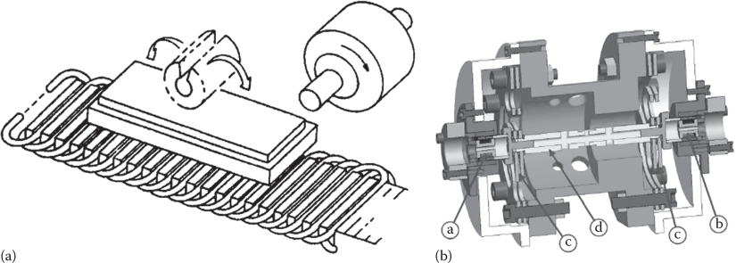
FIGURE 2.1 Linear electric machines (a) with progressive motion (LEMs) (After Boldea, I. and Nasar, S.A., Linear Motion Electromagnetic Devices, Taylor & Francis, New York, 2001); (b) with oscillatory resonant motion (LOMs): motor plus generator (a. linear motor, b. linear generator, c. resonant springs (features), d. coupling shaft). (After Pompermaier, C. et al., IEEE Trans. IE, 58, 2011.)
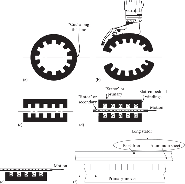
FIGURE 2.2 Double- and single-sided LIMs: (a) round primary, (b) unrolling of primary (after cutting), (c) flat double-sided LIM primary with slots, (d) double-sided LIM primary plus Aluminum (copper) sheet secondary, (e) single-sided LIM (primary) plus Al (copper) sheet, and (f) with back iron in the secondary. (After Boldea, I. and Nasar, S.A., Linear Motion Electromagnetic Devices, Taylor & Francis, New York, 2001.)
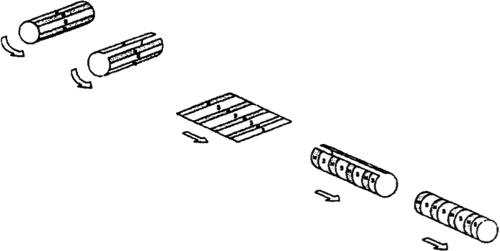
FIGURE 2.3 Flat and tubular LIMs. (After Boldea, I. and Nasar, S.A., Linear Motion Electromagnetic Devices, Taylor & Francis, New York, 2001.)
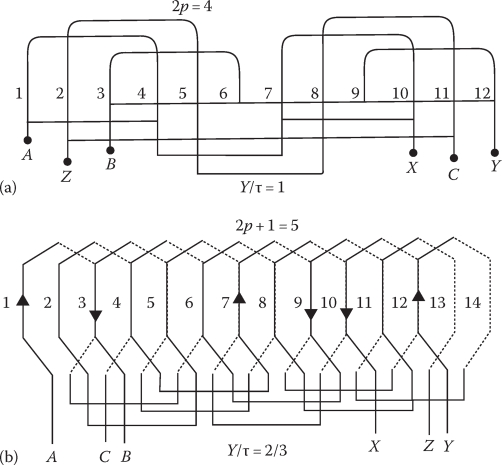
FIGURE 2.4 Typical three-phase LIM windings: (a) with four poles (single layer) and (b) with five poles (double layer). (After Boldea, I. and Nasar, S.A., Linear Motion Electromagnetic Devices, Taylor & Francis, New York, 2001.)
where
ω1 is the primary frequency
Lm is the magnetization inductance
is the equivalent secondary resistance
The short primary of LIM produces a traveling field in the airgap by its three-phase ac currents through the ac windings. This field induces emfs in the secondary plate on iron (or ladder type), and thus secondary currents occur in the secondary. These currents interact with the primary current magnetic field and produce propulsion force (thrust), Fxc.
Also, in single-sided LIMs, a net normal force Fn is developed between the primary and secondary; it has two components: an attraction one Fna—between the primary and secondary iron cores—and a repulsive one Fnr—between the primary and secondary mmfs (magnetomotive forces: ampere turns/pole):
The conventional synchronous (field) speed of LIM is, as for the rotary IM, Us:
with τ the pole pitch of primary winding.
Besides the conventional thrust Fnc, the additional secondary currents, produced mainly at the entrance of the secondary under the primary traveling field, called dynamic longitudinal effect, lead to an end effect force Fxe and a reduction in efficiency and power factor of LIM (this is accentuated by the large mechanical airgap):
where Fxc is the ideal thrust.
The attenuation length of longitudinal end effect currents in the secondary is related to the slip S, goodness factor G, and the number of poles of primary (2p or 2p + 1).
Basically if
the dynamic longitudinal end effect may be neglected and the rotary IM modeling may be extended to such low-speed LIMs.
In contrast, for high-speed LIM condition (2.5) is not fulfilled at full speed (f1), and thus the dynamic longitudinal end effects have to be considered.
Clever adaption in the circuit model of rotary IM have been introduced to handle high-speed LIMs modeling.
A high goodness factor increases conventional performance but also increases the adverse influences of dynamic longitudinal end effects on performance.
So, for high-speed LIMs there is an optimal goodness factor G0 that leads to zero end effect thrust (Fxe)s=0 = 0 at zero slip (S=0); G0 increases linearly with the number of poles as shown in a later chapter dedicated to LIMs.
For low-speed LIMs, in general, the design is approached around the condition
This implies maximum thrust per primary copper losses. The low-speed LIM has found good usage with a ladder-type secondary, for limited travel (a few meters) and an airgap around 1 mm, for moving machining tables in industry in a harsh environment (Figure 2.5).
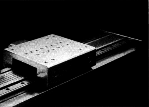
FIGURE 2.5 LIM for a machining table. (After Gieras, J.F., Linear Induction Drives, Oxford University Press, Oxford, U.K., 1994.)
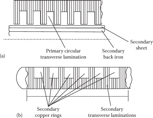
FIGURE 2.6 Tubular LIM with (a) disk shape laminations and (b) secondary copper rings.
Tubular LIMs for short travel (less than 1 m) may be built for robotic applications (Figure 2.6).
In medium (suburban) speed range (30 m/s), the single-sided LIM has found applications both in wheeled (Figure 2.7) and MAGLEV vehicles (Figure. 2.8), after [9].
2.2 Linear Synchronous Motors for Transportation
We mean here, by “transportation,” people movers for urban/interurban purposes.
A first classification of linear synchronous motors (LSMs) may be
Active guideway (long primary) LSMs
Passive guideway (short primary-on board) LSMs
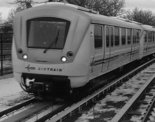
FIGURE 2.7 JFK–New York AirTrain on wheels propulsed by single-sided LIMs. (From http://en.wikipedia.org/wiki/File:JFK_AirTrain.agr.jpg)
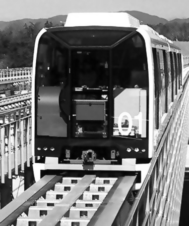
FIGURE 2.8 Linimo MAGLEV (HSST) in Japan, with single-sided LIM propulsion. (From hrttp:// en.wikipedia.org/wiki/File:Linimo_approaching_Banpaku_Kinen_Koen,_towards_Fujigaoka_Station.jpg)
The active guideway LSMs may be built with
DC heteropolar excitation on board (without or with PM assistance) and active guideway with laminated iron core and three-phase windings in slots (Figure 2.9)
DC superconducting heteropolar excitation on board with air-core three-phase cable winding guideway (Figure 2.10)
The peak speed of Transrapid, now commercial in Shanghai, China, is 450 km/h with a flight at 10 ± 2.5 mm height while JR–MAGLEV reached more than 560 km/h with a flight height of about 150 ± 30 mm.
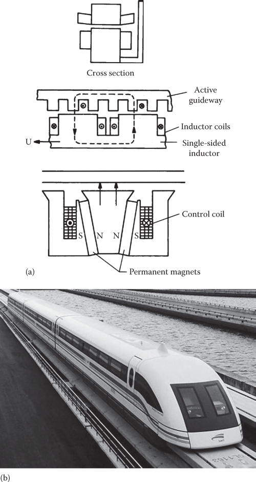
FIGURE 2.9 Active guideway with LSM with dc excitation on board of MAGLEV vehicle (Transrapid, Germany). (a) LSM for propulsation and magnetic levitation and (b) the first commercial Transrapid. (From http://en.wikipedia.org/wiki/File:A_maglev_train_coming_out,_Pudong_International_Airport,_Shanghai.jpg)
The active guideway (stator with three-phase cable ac windings) of both solutions leads to rather expensive initial costs of guideway, especially if we add the 1–3 km sections to be supplied from other power stations on ground, 10–20 km away from each, provided with large power PWM converters and numerous power on/off switches.
But the vehicle is claimed to be less heavy as no large (full) power energy collection on board is required. Some power on board is required to feed the dc excitation coils and auxiliaries that control levitation and guidance, respectively, and to replenish the superconducting coils with current daily, etc. Power on board is transferred, by electromagnetic induction from the long stator mmf space harmonic fields, into dedicated on-board linear generator coils and a backup battery. The major (propulsion) control of such MAGLEVs is done from the ground stations [6].
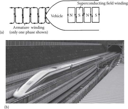
FIGURE 2.10 (a) Active guideway LSM with dc superconducting excitation and (b) on board of vehicle (JR-MAGLEV, Japan). (From http://en.wikipedia.org/wiki/File:JR-Maglev-MLX01-2.jpg)
As with all linear-motor-propulsed vehicles, the direct electromagnetic thrust allows to build lower deadweight vehicles; consequently, lower energy consumption per passenger and kilometer for given commercial speed is obtained. The dedicated active guideway system means notable initial costs in comparison with wheeled high-speed trains (TAGV or similar). But, so far, for urban people movers, the passive guideway LIM-propulsed MAGLEVs (HSST in Japan and Rotem in S. Korea (Figure 2.11)) with separate dc-controlled electromagnets for levitation and guidance control have been introduced in LIM-MAGLEVs with full power transfer on board.
A vehicle with full power PWM converters on board for propulsion control is required.
However, as IGBT PWM converters can be built today at less than 1 kVA/kg, the additional weight is not prohibited anymore.
Consequently, the rather moderate cost of passive guideway prevails. Still the LIM moderate performance (70%–75% efficiency and (0.5–0.6) power factor) makes the search for better passive guideway solutions very welcome.
A homopolar LSM was introduced for integrated propulsion levitation of passive guide-way (made of solid iron segment poles and air interpoles) higher performance MAGLEVs (Figure 2.12).
Here, both the dc and ac windings are on board and so are the PWM power converters. Full power transfer to the vehicle is required. But the track is made of solid iron segments spaced with 2τ period.
Experiments have demonstrated 80% propulsion plus levitation efficiency at 0.8 power factor for less than 2 kVA/ton for levitation at 8–10 m/s [7], with the H-LSM providing 10/1 levitation/own weight ratio, for natural cooling.
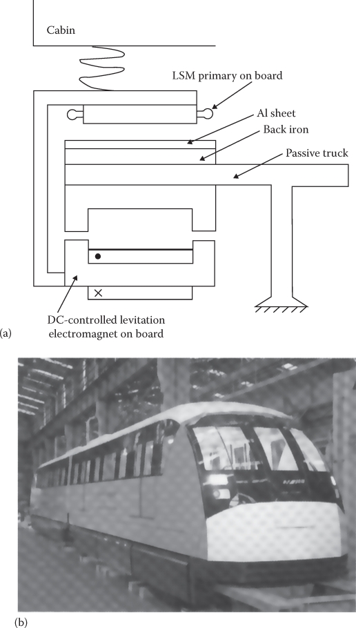
FIGURE 2.11 The urban Korean MAGLEV with LIM propulsion and additional dc-controlled levitation and guidance electromagnets: (a) generic structure and (b) general view.
Other passive guideway LSMs have been recently investigated for transportation in industrial rooms or for people movers.
Some of them such as the reluctance LSMs (with three phases), the transverse-flux PM LSMs, or the six-phase brushless two-level bipolar current controlled reluctance linear motors (with two field phases and four thrust phases at any time) and switched reluctance LSMs will all be treated in dedicated chapters of this book.
They all share a passive variable reluctance laminated guideway with short primary on board of vehicle. The simplicity and low cost of the passive guideway are attractive features of such LSMs, despite full power transfer and larger kVA rating PWM converters on board of vehicles.
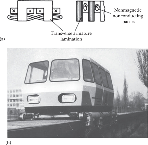
FIGURE 2.12 Homopolar linear synchronous motor (H-LSM), as an integrated propulsion-levitation system for a passive guideway MAGLEV (Magnibus 01). (a) Homopolar linear synchronous motor and (b) general view. (From Boldea, I. et al., IEEE Trans., VT-37(4), 213, 1988.)
2.3 Industrial Usage Linear Synchronous Machines
By industrial usage, we mean various industrial applications with limited travel (less than 2–3 m) and wheels or bearings suspension and LSM propulsion, with magnetic suspension and LSM propulsion, or with magnetic suspension for single axis or X–Y linear motion precise positioning. There is a myriad of topologies proposed so far; here we will refer to a series of such devices fabricated by a few manufacturers, to give a coherent up to date status of the field.
LSMs provide linear motion high position speed control performance advantages, such as
High accuracy: down to 2.5 µm/300 mm travel
High repeatability: resolution to 0.1 µm
No backlash due to direct driving
Faster acceleration (1–10 g) than rotary motors with rotary to linear transmission solutions
Higher linear speeds (up to 8 m/s) for faster travel to excursion end
High reliability for long life due to simplicity
Low maintenance costs
Compatibility with clean rooms
Typical industrial applications include
Bottle labeling, baggage handling, electronic assembly, food processing, laser cutting machines, laser surgery equipment, machine tools, mail sorting, material handling, packaging devices, part transfer systems, PCB assembly/inspection/drilling, precision grinding, printing applications, robotics, surface mount assembly, wafer etch machines, and vision inspection
Ball-screw or timing belt rotary (stepper) drives have been drastically surpassed in positioning performance by LSMs of various types (Table 2.1).
TABLE 2.1
Performance Comparison: Ball-Screw/Timing Belt Rotary Steppers versus PM-LSMs
Close Loop |
Open Loop |
|||
Rotary |
LSM |
Rotary |
LSM |
|
Maximum speed (m/s) |
1 |
10+ |
2.5 |
10+ |
Maximum acceleration (m/s2) |
20 |
98+ |
20 |
98+ |
Repeatability (µm) |
50 |
1 |
250 |
10 |
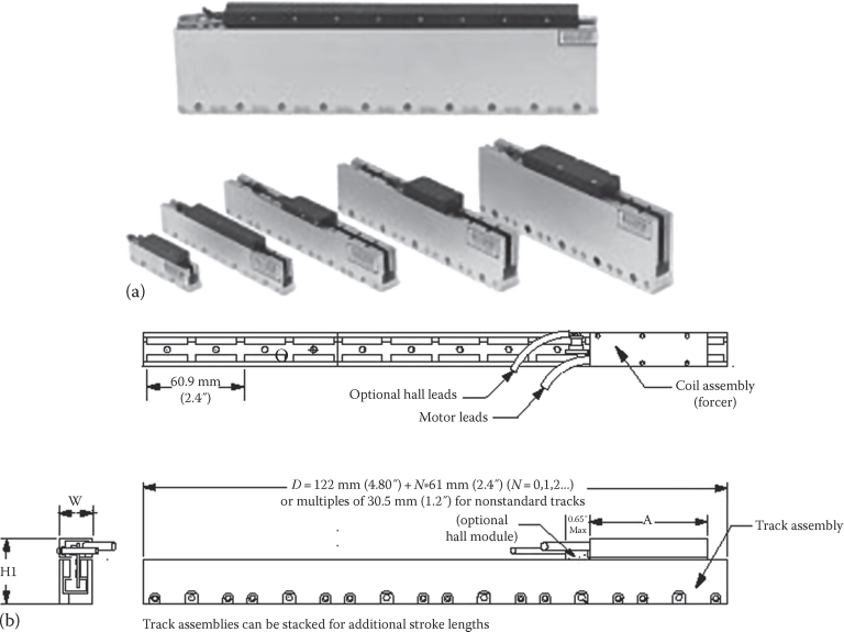
FIGURE 2.13 Commercial iron-core double-sided PM-LSM (a) general view and (b) detailed geometry. (From http://www.baldormotion.com/products/linearproducts/lmcf.asp)
Two representative LSMs are built with PM tracks and three-phase ac windings on the mover, which is fed through a flexible power cable:
Air-core (cogging force free) PM-LSM, Figure 2.13
Iron-core PM-LSM, Figure 2.14
The double-sided track uses a U-shape solid iron core and a row of NSNS PMs along the travel length. The short primary with a three-phase ac winding (similar to those of LIMs, but also of nonoverlapping coil type as shown later in the book) is fixed in an insulation adhesive or core, respectively, in a laminated core.
When superprecision in positioning and superfast response are required with very low vibrations, the air-core PM-LSM is used despite its larger PM weight and lower efficiency, for same thrust and speed, than iron-core PM-LSMs. Linear stepper motors in single- and dual-axis motion configurations are also fabricated due to their simplified control. To avoid the limitation of the flexible power cable in some applications brush-dc PM linear motors are still used (Figure 2.15).
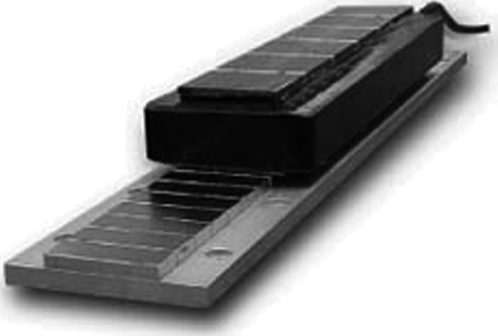
FIGURE 2.14 Commercial iron-core double-sided PM-LSM. (From http://www.baldormotion.com/products/linearproducts/lmic.asp)
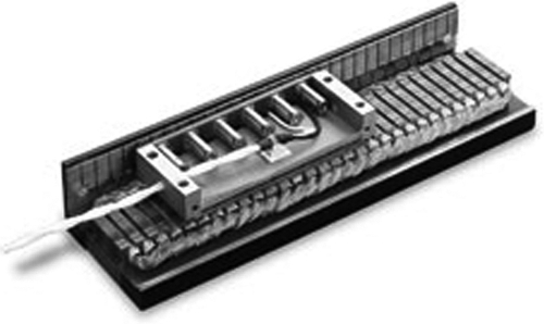
FIGURE 2.15 Commercial brush-dc PM linear motors.
2.4 Solenoids and Linear Oscillatory Machines
Plunger solenoids produce thrust over a limited length (Figure 2.16 [8, 9]), but also up to even 0.3 m in special PM configurations in single-phase (coil) movers with PM tracks [9].
The coil current is modified to control the airgap as constant (as for magnetic suspension in MAGLEVs) or as variable, according to a planned “trip” (as in valve actuators for internal combustion engines or in high-power electromagnetic power-switch drives).
With numerous applications, such as door lockers in hotels, plunger solenoids are a growing industry (Figure 2.17), and they will be discussed in a chapter in the book.
The principle of the microphone/speaker and of a linear vibrator is illustrated in Figure 2.18a and b, while a long stroke (up to 0.3 m) moving coil PM actuator is illustrated in Figure 2.18c.
A homopolar PM piece (cylindrical or flat) produces the magnetic field—which interacts with current (i) in an air-core coil—mover to produce thrust :
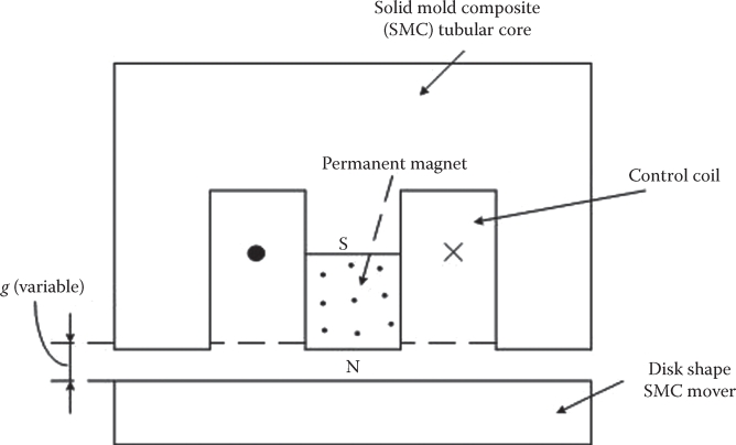
FIGURE 2.16 PM-plunger solenoid with control coil.
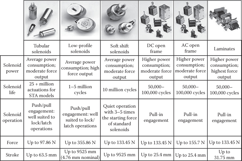
FIGURE 2.17 Sample commercial linear solenoids. (After http://www.solenoids.com/linear_solenoids.html)
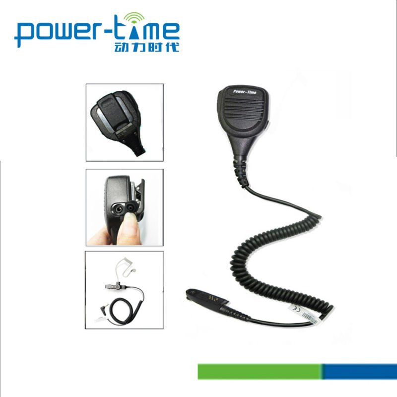
A typical handheld commercial speaker appears in Figure 2.19a, while a waterproof speaker/microphone is shown in Figure 2.19b.
Resonant linear oscillatory motors and generators also use PMs and single-/multiple-coil single-phase currents (Figure 2.20) for strokes up to ±25 mm (Figure 2.21a and b) or in applications such as refrigerator-compressor drives (Figure 2.21a) or Stirling engine-driven linear electric generators (Figure 2.21b).
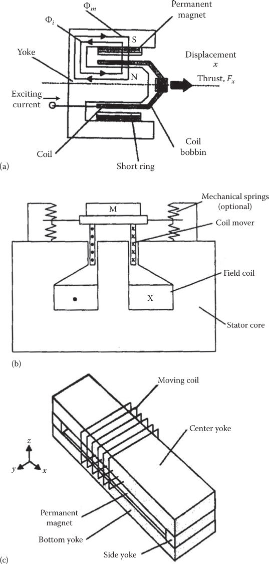
FIGURE 2.18 (a) Speaker/microphone, (b) linear vibrator, and (c) moving coil PM actuator. (After Boldea, I. and Nasar, S.A., Linear Motion Electromagnetic Devices, Taylor & Francis, New York, 2001.)
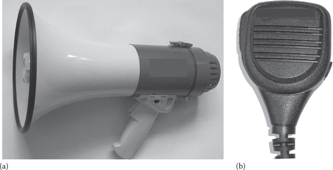
FIGURE 2.19 Sample commercial speaker/microphone: (a) handheld (After http://www.alibaba.com/product-gs/667141691/professional_wireless_microphone_for_recording.html) and (b) waterproof (After http://i00.i.aliimg.com/photo/v1/424513460/Handheld_speaker_mic_Water_resistant_IP54_for.jpg).
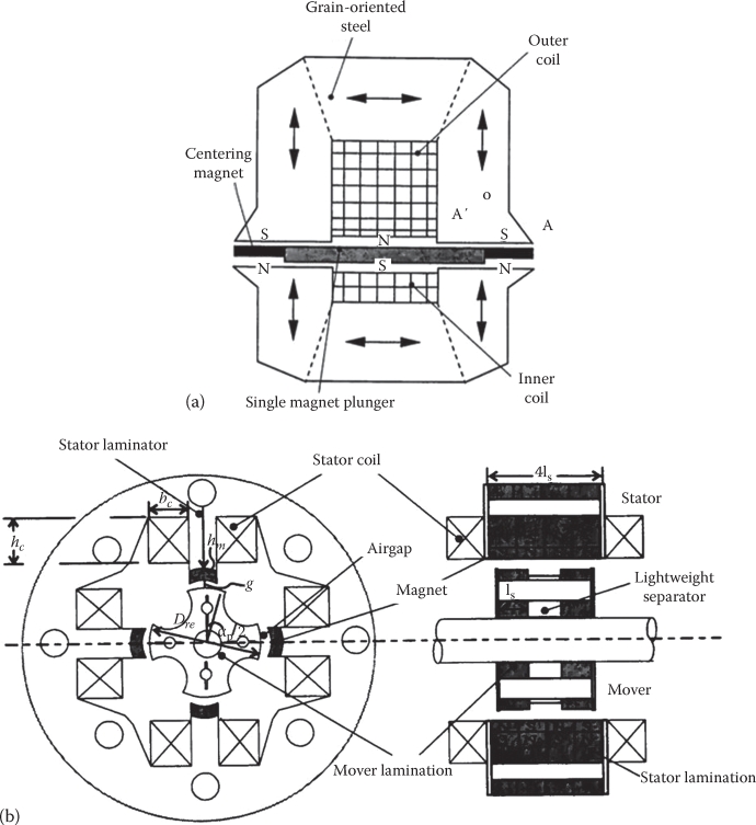
FIGURE 2.20 Resonant linear oscillator machines with: (a) PM mover and (b) iron mover. (From Boldea, I. and Nasar, S.A., Linear Electric Actuators and Generators, Cambridge University Press, London, U.K., 1997.)
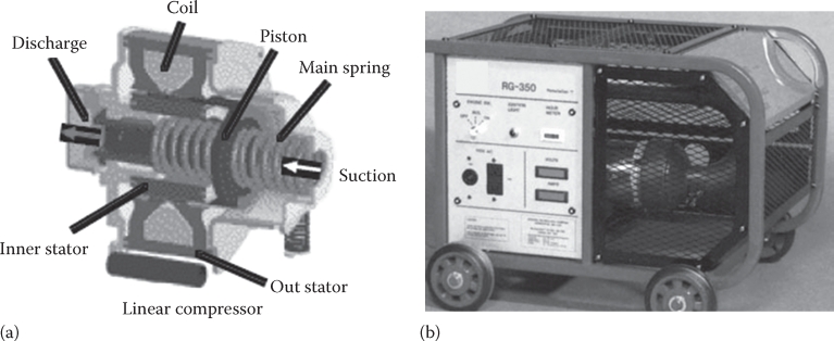
FIGURE 2.21 Commercial linear compressor drive: (a) by L.G. and (b) by S.T.C. (After http://spinoff.nasa.gov/spinoff2002/er_9.html)
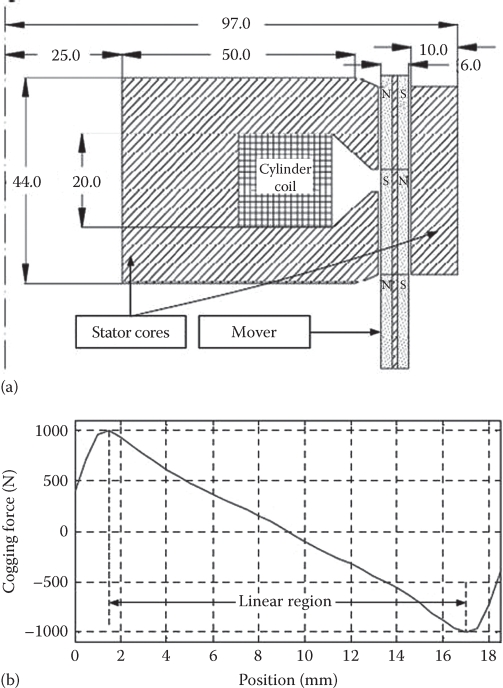
FIGURE 2.22 Springless resonant LOM: (a) cross section and (b) cogging force (“magnetic spring”). (After Boldea, I. et al., Springless resonant linear PM oscillomotors, Record of LDIA-2011, Eindhoven, the Netherlands, 2011.)
The PM mover device (Figure 2.20a) leads to a lower weight mover (lower rigidity mechanical spring), while the core-mover device protects better (thermally and mechanically) the PMs placed on the stator (Figure 2.20b). Commercial embodiments of LOMs are shown in Figure 2.21.
Efficiency above 0.9 from 50 W upward has been obtained with such resonant LOMs with PMs both in motoring and generating. As the mechanical spring has to be designed with its rigidity k corresponding to the electric frequency f1,
Extreme precision is required in manufacturing to match (2.8), unless the LOM is single-phase inverter-fed, when the electrical frequency f1 is adjusted to the mechanical eigen frequency fm.
In an effort to replace the mechanical spring entirely—for cost and volume reduction reasons—particular designs of LOM capable of large enough and linear and centralizing cogging (zero current, PM) force have been proposed recently (Figure 2.22) for a 1.9 kW, 2 kg mover, ±7.5 mm motion, at 41 Hz at above 0.9 efficiency for 10 kg of active materials [10].
2.5 Summary
Linear electric machines are counterparts of rotary electric machines, and thus there are LIMs, LSMs, and dc-brush linear motors.
Linear electric machines are reversible and thus transit easily from motoring to generating modes.
In applications, linear progressive or linear oscillatory motion control is needed.
In general, for linear progressive motion, even with frequent returns, three (two)-phase ac or dc brushless linear motors are used.
In contrast, for linear oscillatory motion at controlled frequency for small strokes (50 mm or less), single-phase (coil) linear PM synchronous motors/generators are used.
Linear electric machine (LEM) topologies are flat (single or double sided) or tubular— only for short travels (max. 1–1.5 m).
Three-phase ac windings of LEMs are similar to those of rotary machine counterparts, but, for double-layer topologies, they have 2p + 1 poles (with half-filled end-pole slots).
Linear induction motors (LIMs)—in single-sided flat configuration with short primary and long (fixed) secondary are used for low speed (machine table movers) or high speed (urban/interurban people movers).
To reduce costs, the long fixed secondary of LIMs is made of an aluminum sheet fixed by bolts to a solid back iron slab but, to increase efficiency and power factor, a ladder-type secondary with a stator laminated core is preferable (for short travels: a few meters).
Due to its ruggedness, LIMs via variable voltage and frequency converters may adapt to both people movers and industrial transport uses; such applications have become an industry by offering lower cost good performance transport.
The rather large airgap of LIMs in transportation led to lower than desired efficiency and power factor (0.8 and 0.6, respectively) penalizing the kVA ratings of the PWM converter used for speed control. This is how linear synchronous motors (LSMs) came into play.
LSMs may be first classified as
Active guideway (primary)
Passive guideway (secondary)
In active guideway LSMs, the primary laminated core with its three-phase ac windings is spread along the entire travel length and is fed through on-ground converters in sections, to reduce energy consumption.
The long primary is wound with a cable winding for a q = 1 slot/pole/phase single-layer winding. A q=½ nonoverlapping winding is also feasible to reduce guideway initial costs.
On board of mover there is a dc excitation source:
With dc excitation coils (without or with PM assistance)
With dc superconducting excitation
The active guideway LSMs have found applications in superhigh-speed trains with magnetic levitation. The LSM provides integrated levitation and propulsion or, in addition, guidance control (in superconducting MAGLEV vehicles).
Passive guideway LSMs include
Homopolar LSMs (H-LSM)
Transverse-flux PM-LSMs
Reluctance LSMs
Switched reluctance LSMs
Multiple-phase bipolar two-level current reluctance brushless linear machines
Only the H-LSM has been proved on a prototype for an urban MAGLEV vehicle, but all the other types are candidates in both people movers and for indoors transporters.
Besides people movers, industrial linear position (speed) control is today realized on many occasions by LSMs or dc-brush PM linear motors with higher quickness, precision, and repeatability than ball-screw rotary motor actuators.
Both air-core and iron-core primary PM-LSMs in flat and tubular topologies are commercial or proposed for single- or multiple-axis linear motion control in various applications, from movable tables to robot arms.
Short stroke linear oscillatory motors, mostly in single-phase (coil) PM linear synchronous embodiments, are in commercial use as loudspeakers/microphones, gas-compressor drives, or Stirling or internal combustion engine-driven linear generators [11].
Such linear oscillomachines (LOMs) work at resonance and thus need mechanical well-calibrated springs. To eliminate the mechanical springs, but keep the resonance conditions, to secure very good efficiency, special designs with large, linear, and centralizing cogging force in PM LOMs have been recently proposed.
Finally, solenoids (electromagnets)—dc or ac fed—without or with PM assistance, with simple or sophisticated position control, have constituted for quite some time an industry with applications from hotel door lockers to electromechanical power-switch drives.
Quite a few applications of LEMs or LOMs have been named or illustrated in this chapter.
Subsequent chapters will analyze most LEM and LOM topologies in terms of modeling, design, and control for specific applications.
References
1. S.A. Nasar and I. Boldea, Linear Motion Electric Machines, John Wiley Interscience, New York, 1976.
2. I. Boldea and S.A. Nasar, Linear Motion Electromagnetic Systems, John Wiley & Sons, New York, 1985.
3. J.F. Gieras, Linear Induction Drives, Oxford University Press, Oxford, U.K., 1994.
4. J.F. Gieras, Linear Synchronous Motors, 2nd edn., CRC Press, Boca Raton, FL, 2000.
5. C. Pompermaier, F.J.H. Kalluf, A. Zambonetti, M.V. Ferreira, and I. Boldea, Small linear PM oscillatory motor magnetic circuit modeling corrected by asymmetric FEM and experimental characterization, IEEE Trans. IE, 58, 2012, 1389–1396.
6. H.-W. Lee, K.-C. Kim, and J. Lee, Review of MAGLEV train technologies, IEEE Trans., MAG-42(7), 2006, 1917–1925.
7. I. Boldea, I. Trica, G. Papusoiu, and S.A. Nasar, Field tests on a Maglev with passive guideway linear inductor motor transportation system, IEEE Trans., VT-37(4), 1988, 213–219.
8. I. Boldea and S.A. Nasar, Linear Electric Actuators and Generators, Cambridge University Press, London, U.K., 1997.
9. I. Boldea and S.A. Nasar, Linear Motion Electromagnetic Devices, Taylor & Francis, New York, 2001.
10. I. Boldea, S. Agarlita, and L. Tutelea, Springless resonant linear PM oscillomotors, Record of LDIA-2011, Eindhoven, the Netherlands, 2011.
11. R.Z. Unger, Linear compressors for clean and specialty gases, Record of1998 International Compressor Engineering Conference, Purdue University, West Lafayette, IN, 1998.
12. http://en.wikipedia.org/wiki/File:JFK_AirTrain.agr.jpg
15. http://en.wikipedia.org/wiki/File:JR-Maglev-MLX01-2.jpg
16. http://www.baldormotion.com/products/linearproducts/lmcf.asp
17. http://www.baldormotion.com/products/linearproducts/lmic.asp
18. http://www.baldor.com/support/Literature/Load.ashx/BR1202-G?LitNumber=BR1202-G
19. http://www.solenoids.com/linear_solenoids.html