
Now that you're armed to the…er, fingertips with your Linux commands and can happily control your BeagleBone Black remotely like a pro, it's time to get physical with the board. So, to begin with our exercises in physical computing, we're whipping up some essential recipes on the following topics:
- Controlling external LEDs
- Using buttons – button press function
- Using analog sensors
- Variable resistance sensor – photocell
- Using motors
Our programming language of choice will principally be JavaScript in tandem with BoneScript, which is a Node.js and browser-side library. We will also include or reference a few Python script analogues to broaden our skills with the hardware.
The basics of physical computing typically require understanding and shaping input and output on your hardware. We will begin with taking a look at the old chestnut, manipulating LEDs, an experience you're likely to have some familiarity with if you have read the last chapter, or if you're an Arduino or Raspberry Pi user. Next, we'll play a bit with buttons because who doesn't like to push a button? Then, it gets more interesting as we add sensors to the mix. After this, we'll give you some basic recipes for locomotion that use some motors. Finally, we'll wind it up with the ingredients and steps for setting up a connection between your BBB and an Arduino board.
We'll march across the BBB, draft the large army of pins that the board has at our disposal, the GPIOs, ADCs, PWMs, and UARTs, a phalanx that makes the Raspberry Pi look feeble. All of these acronyms may seem impenetrable; however, throughout the course of this book we will steadily learn something about all of them.
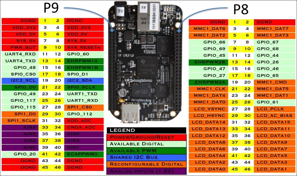
Header pin array with their various functions designated by pin number
Although we will have a dash of Python code here and there, the recipes in this chapter will primarily consist of BoneScript/JavaScript ingredients and its powerful potions for physical computing. For an extensive documentation of the BoneScript Library and its up-to-date reference, refer to http://beagleboard.org/Support/BoneScript.
Before we head off to the recipe land (and since this chapter is actually about how to make some basic electrical circuits), we need to take a quick look at some of the foundational principles of electricity and current. Knowing a few things about them will prevent you from accidentally frying your board.
How much power does an LED need? What would happen if I ran a 5V circuit with a 3V power supply? Will my 12V battery pack keep the robot going long enough to get the data I need? Also, most importantly, can I attach the Spottiswoode Great Induction Coil Cape to pins 9_11 and 37 on the BeagleBone Black?
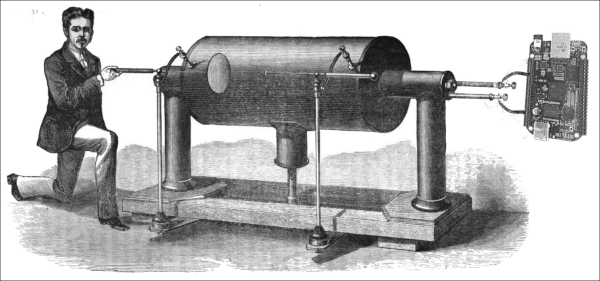
Source: William Spottiswoode and induction coil from Wikimedia Commons / The London, Edinburgh, and Dublin Philosophical Magazine, 1877. Image composite by Charles Hamilton.
To discover the answer to these and other (potentially) board burning questions, you need to know a bit about the three pillars of electronics wisdom and wiring: current, voltage, and resistance:
- Current: The continuous flow of electrons, or the rate of "charge" through a given point in a circuit.
- Voltage (potential difference): This indicates the size of the electrical potential in your circuit that allows electrons to flow. Specifically, voltage is the difference in the electrical potential between two given points that allows electrons to move. This is why it is known as the potential difference.
- Resistance: This denotes that electrons get hung up from Point-A to Point-B, that is, there is friction that can impede their free flow of current, which we call resistance.
How do all these things relate to one another when it comes to circuitry?
The easy answer is Ohm's law. Much ink has been spilled in explaining this foundational principle of electricity; we will only say a few words and quickly throw a formula at you, the only one you will see in this book: V = I x R.
Knowing how to use this basic formula will help you determine the right combination of current and resistance to apply when you wire up your BBB circuits. Here is the breakdown of the formula:
- V: This specifies voltage (expressed in volts)
- I: This indicates current (expressed in amps)
- R: This denotes resistance (expressed in ohms and commonly seen as Ω)
As long as we know any two of the three variables, we will use Ohm's law to calculate the third and remaining number. Typically, you will need to use Ohm's law to determine the right resistor to use when you wire up a circuit.
There are numerous and exhaustive free examples available online that show you how to use Ohm's law for your projects. Here are a few excellent ones:
- Sparkfun's tutorial on Voltage, Current, Resistance, and Ohm's Law is one of the best for beginners and is available at https://learn.sparkfun.com/tutorials/voltage-current-resistance-and-ohms-law
- Collin Cunningham, formerly of Make magazine and now an Adafruiter, gives us the video version skinny at https://www.youtube.com/watch?v=-mHLvtGjum4
- A very handy online Ohm's law calculator tool is available at http://www.onlineconversion.com/ohms_law.htm
The magical thing about microcomputers is that they give you the ability to interact with the physical world. This interaction is essentially possible via the GPIOs and other pins. These pins are intended to generate different voltage levels and pulses. This is the essential purpose of programming a GPIO: you will tell the board to generate a specific level of voltage or pulse on a specific pin.
Perusing our complement of I/O pins, we can count two rows of 46 pin slots on the two expansion headers. If you look closely, you will see that one block is labeled P8 and the other one P9. All the references to a specific pin begin with this block number first, followed by a number between 1 and 46. Therefore, the example pins look similar to P8_2, P8_15, P8_24, P9_2, P9_15, and so on.
But what do you do with all these pins? Not all of them are actually available. Some have been drafted for other purposes. According to the BBB reference manual, the board has the following breakdown for pin purposes and availability:
|
# of Pins |
Purpose of pins |
|---|---|
|
65 |
General purpose and digital IO pins |
|
8 |
PWMs |
|
4 |
Timers |
|
7 |
1.8V analog inputs |
|
4.5 |
UARTs |
|
2 |
I2C |
|
2 |
SPI |
|
2 |
5V |
|
2 |
3.3V |
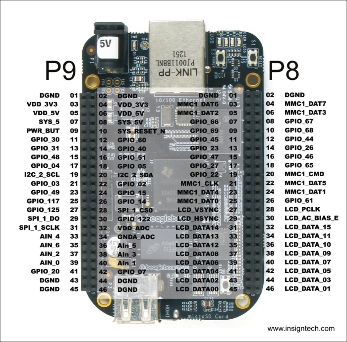
To understand the nitty-gritty of the pins that may be available, you can refer to the BeagleBone Black System Reference Manual at http://elinux.org/Beagleboard:BeagleBoneBlack. Page 84 describes the pins on the P8 header, and page 86 describes the pins on the P9 header. There are also numerous reference guides online that help you understand the BBB's pin layouts. Skip to the There's more… section for additional sources. In the meantime, the following image a snapshot view of the board's entire pinmux. You can also refer back to the pin mapping diagram at the beginning of this chapter.
A common frustration among new BBB users is that the pins do not always respond as expected. This is because, by default, some header pins are assigned to specific tasks, such as the HDMI output, some are used for multiple purposes, and many of its functions are only available after some tweaking. For example, pin 21 on the P9 header wants to be a GPIO at some time, whereas at other times, it wants to be a PWM, a UART, an I2C, or a SPI pin.
So, how do you get around this pin schizophrenia? Well, you have to reconfigure it for this purpose, a process known as pin multiplexing or pinmux. Pinmuxing is fairly straightforward and can be easily handled from the command line. We will encounter this technique later in this and subsequent chapters.
Although the BBB's sophisticated pin design can accept different types of signals, in this chapter, we will mainly take a look at the two types that are commonly used in physical computing:
- Pulse width modulation (PWM)
- Analog to digital converter (ADC)
Within our toolset is another software application that electronics and hardware makers rely heavily on: Fritzing. You may already be familiar with it, but if not, Fritzing is an extremely, handy open source graphical tool for creating diagrams of breadboards, schematics, and PCB layouts without the need for traditional engineering schematics.
Note
Before wiring up your breadboard, it's a good idea to reset the BBB each time you perform a new recipe by powering it down. This ensures that the pins are reset to their input state. Otherwise, if the pin is being used as an input in a new recipe that was previously used as an output, you may damage your BBB.
Here are some of the sources and links to the BeagleBone Black's pin layouts:
- One of the best pin-mapping guides is Eskimon's interactive overlay at http://eskimon.fr/beaglebone-black-gpio-interactive-map.
- The full expansion header layout is at http://elinux.org/Beagleboard:Cape_Expansion_Headers
- A more succinct diagram of GPIOs is available at http://stuffwemade.net/post/beaglebone-pinout-new.
- Collars that you can attach to the BBB that provide easy call outs for the GPIO pins is available at http://www.doctormonk.com/2014/01/beaglebone-black-collars.html.
- Take a look at how to use BeagleBone Black GPIOs at http://www.armhf.com/using-beaglebone-black-gpios/.
- A quick guide on how to pinmux is available at http://beaglebone.cameon.net/home/pin-muxing.
- Derek Molloy's Beaglebone: GPIO Programming on ARM Embedded Linux tutorial and video is another comprehensive and thoughtful introduction available at http://derekmolloy.ie/beaglebone/beaglebone-gpio-programming-on-arm-embedded-linux/.