
Chapter 14
Energy Storage Systems for Electric Power Utility Systems
Nothing comes from nothing.
The darkness comes from darkness.
Pain comes from the darkness.
And we call it wisdom. It is pain!Randell Jarrell
Power when wielded by abnormal energy is the most serious of facts.
Henry Brooks Adams
14.1 Introduction*
In the past, batteries of all sizes have been part of everyday applications for decades. For example, besides automobiles, battery rooms were also found in electric power plants and substations where reliable power was required for operations of switchgear, critical standby systems, and possibly black start of the station. Often batteries for large switchgear lineups were 125 or 250 V nominal systems and feature redundant battery chargers with independent power sources. Separate battery rooms might have been provided to protect against loss of the station due to a fire in a battery bank. For stations that were capable of black start, power from battery system might have been required for many purposes including switchgear operations.
However, for a long time, large utility-scale batteries have been slow to develop, due to technological limitations and the demands and costs of delivering utility-scale power, when necessary, for use on the grid. Recent developments indicate that utility-scale batteries finally reached a point of technological development in which they can be integrated into grid in select applications to ensure a constant power supply. This development will affect the entire alternative energy field, as large amounts of electricity generated by alternative means from solar to wind to any alternative power source can be stored in large quantities and used when necessary. This development requires huge wind installations or solar applications that could someday provide reliable electricity throughout the world. In summary, the use of intermittent or variable sources of energy, such as solar and wind energies, and some of the forms derived from moving water, often requires some means of energy storage.
Energy storage can not only potentially benefit solar energy systems as well as other renewable energy resources but also benefit the transmission and distribution systems because storage applications can be used to mitigate diurnal or other congestion patterns and, in effect, store energy until the transmission system is capable of delivering it where needed. By storing energy from variable resources, such as wind and solar power, energy storage could provide firm generation from these units, permit the energy produced to be used more efficiently, and provide supplementary transmission benefits.
Therefore, the adverse impacts of large-scale photovoltaic (PV) power generation systems connected to the power grid and developed output control technologies with integrated battery storage are still under the study. The sodium–sulfur (Na–S) battery is designed to absorb fluctuations in the PV output within its limit of kW and kWh capacities. For more efficient and effective operation of the Na-S battery, several control algorithms of a battery system for smoothing PV output are being developed by the industry [1].
14.2 Storage Systems
At the present time, there is a great interest in the possible applications of energy storage in power systems. The interested parties include the electric utilities, energy service companies, and automobile manufacturers (for electric vehicle applications). For example, the ability to store large amounts of energy would permit electric utility companies to have greater flexibility in their operation because with this option, the supply and demand do not have to be matched instantaneously. Hopefully, the availability of the proper battery at the proper price will finally make the electric vehicle a reality.
The battery technologies are diverse and at different stages of development. They include a variety of batteries: high-speed flywheels, supercapacitors, and regenerative fuel cells. Local energy storage would assist interms of embedded generation from renewable energy by providing a buffer between the variability of supply and demand. Potential benefits include capacity reduction, frequency support, standing reserve provision, and cold start capability. Depending on technical requirements, and geographical settings, a given utility may avail one or more of these technologies.
Power applications, such as uninterruptible power supply backup for data centers and automotive starting batteries, represent the largest market for lead-acid batteries, whereas laptop batteries and power tools have caused incredible growth for lithium-ion. For bulk energy storage in utility grids, pumped hydropower plants dominate, with approximately 100 GW in service around the world.
Even though many utilities possess pumped storage plant, little focus has been placed on their proper potential roles in meeting power demand or shave off demand peaks, and this way partially decouple energy production from energy consumption. Energy storage can perform the same roles, but may also be used as a generation source, either replacing expensive, low-efficiency storage capability or load scheduling, and the generation capacity would be required to meet the average electrical demand only rather than the peak demand. Expensive network upgrades can be deferred.
By enabling thermal generating units to operate closer to rated capacity, higher thermal efficiencies are achieved, and both system fuel costs and CO2 emissions are reduced. Even further benefits also come from reducing demand variability, and thus the requirement for load cycling of generating units and the requirements for additional regulating reserves. As a result, the balancing costs that may be associated with wind variability can be reduced. Also, expensive standing reserve, in the form of open-cycle gas turbines, diesel engines, etc., can also be reduced, since both energy storage and load management can provide a similar role. In general, power applications would be storage systems rated for 1 h or less, and energy applications would be for longer periods. Figure 14.1 presents a comparison of storage technologies in terms of power-level applications and storage time.
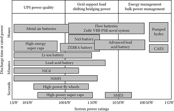
Today, power applications for each of these technologies are being found in electric grid. For example, in the transmission system for bulk power storage as well as in the residential feeder circuit for smaller systems. The following abbreviations are used in Figure 14.1: Li-ion for lithium-ion battery, NiCd for nickel–cadmium, NiMH for nickel–metal hydride battery, CAES for compressed air energy storage, SMES for superconducting magnetic energy storage, VRB for vanadium redox battery, ZnBr for zinc–bromine battery, Na–S for sodium–sulfur battery, Zebra battery for hightemperature battery (used at substations), and super caps for supercapacitors.
14.3 Storage Devices
The list for conventional technologies includes the large hydro, compressed air energy storage (CAES), and pumped hydro.
14.3.1 Large Hydro
It is an oldest renewable source of power/energy. Small hydro systems vary from 100 kW to 30 MW, while micro hydropower plants are smaller than 100 kW. Small hydropower generators work at variable speeds because the water upon which they depend flows at variable speeds. Induction generators are normally used with turbine system. The turbine converts the water’s (kinetic) energy to mechanical rotational energy. The available power (P) from the water flow is expressed as where
Q is the discharged water in m3/s
H is the net head in m
Hydroelectric plants typically have fast ramp-up and ramp-down rates, proving strong regulating capabilities, and their marginal generation cost is close to zero. In many countries, a natural synergy exists between hydroelectric generation/pumped storage and wind power. Clearly, if hydro generation is being replaced by wind energy, then emission levels will not be affected, but the hydro energy can be transformed into potential energy stored for later use. Existing hydroelectric plant can reduce the output, using reservoirs as storage, to avoid wind energy curtailment.
14.3.2 Compressed Air Storage
It involves the storage of compressed air in disused underground cavities, for example, exhausted salt mines. Alternatively, an underground storage complex can be created using a network of large diameter pipes. Later, the compressed air can be released as part of the generation cycle, providing a cycle efficiency of approximately 75%. In an open-cycle gas turbine or combined-cycle gas turbine plant, incoming air is compressed by the gas turbine compressor before being ignited with the incoming fuel supply. The exhaust gases are then expanded within the turbine, driving both an electrical generator and the compressor.
A modern CAES is a peaking gas turbine power plant that consumes less than 40% of the gas used in a combined-cycle gas turbine (and less than 60% gas is used by a single-cycle gas turbine) to produce the same amount of electric output power. It is accomplished by blending compressed air to the input fuel to the turbine by compressing air during peak periods at lower costs than conventional stand-alone gas turbines.
It is required that plants are near proper underground geological formations, such as salt caverns, mines, or depleted gas wells. The first commercial CAES plant was a 290-MW unit built in Handorf, Germany, in 1978. The second one was a 110-MW unit built in McIntosh, Alabama, in 1991. They are fast-acting units and typically can be put into service in 15 min when it is required. The Electric Power Research Institute has developed an advanced CAES system designed around a simpler way using advanced-turbine technology. The largest plant under consideration in the United States has a rating of 800 MW.
14.3.3 Pumped Hydro
The most widely established large-scale form of energy storage is hydroelectric pumped storage. It is an excellent energy storage technique, but unfortunately, few attractive sites exist and initial investment costs are very high. Typically, such plant operates on a diurnal basis—charging at night during periods of low demand (and low-priced energy) and discharging at day during times of high or peak demand. A pumped storage plant may have the capacity for 4–8 h of peak generation with 1-2 h of reserve, although in some cases, the discharge time can extend to a few days.
A typical pumped hydro plant consists of two interconnected reservoirs (lakes), tunnels that convey water from one reservoir to another, valves, hydro machinery (a water pump—turbine), a motor-generator, transformers, a transmission switchyard, and a transmission connection. The amount of stored electricity is proportional to the product of the total volume of water and the differential height between reservoirs. For example, storing 1000 MWh (deliverable in a system with an elevation change of 300 m) dictates a water volume of about 1.4 million m3. The earliest application of pumped hydro technology was in Zurich, Switzerland, in 1882. It was realized early that a Francis turbine could also be used as a pump, such as the one used in the Hiwassee Dam Unit 2, in 1956, and has a rating of 59.5 MW.
Today, the global capacity of pumped hydro storage plants totals more than 95 GW, with approximately 20 GW operating in the United States. The original intent of these plants was to provide off-peak base loading for large coal and nuclear plants to optimize their overall performance and provide peaking energy each day. Since then their duties also include frequency regulation in the generation mode.
There are also less conventional technologies, including hydrogen, flywheels, high-power fuel cells, high-power supercapacitors, superconducting magnetic energy storage (SMES), heat or cold storage systems, and high-power batteries.
14.3.4 Hydrogen
Hydrogen has been proposed as the energy store (carrier) for the future and the basis for a new transport economy. The reasons for this are simple: hydrogen is the lightest chemical element, thus offering the best energy/mass ratio of any fuel and in a fuel cell can generate electricity efficiently and cleanly. Indeed, the waste product (water) can be electrolyzed to make more fuel (hydrogen).
Hydrogen can be transported conveniently over long distances using pipelines or tankers, so that generation and utilization take place in distinct locations, while a variety of storage forms are possible (gaseous, liquid, metal hydrating, etc.). It can be produced by the electrolysis of water using energy from a renewable resource. It can then be burned as a fuel to generate electricity.
Alternatively, it can be piped as a gas or liquid to consumers to be used locally providing both electricity and heating in a total energy scheme, or it can be used for transport. For transport needs, fuel cells in vehicles combine multi-fuel capability, high efficiency with zero (or low) exhaust emissions, and low noise.
The combustion of hydrogen provides energy plus water with no harmful emissions or by-products. If electricity is the final product, this process may not be attractive since the overall efficiency is usually below 50%. Because of this, the interest in hydrogen is usually for transportation purposes, which also depends on having proper storage systems.
In the future, hydrogen pipeline infrastructures are likely to be developed around the world. Excess hydrogen (i.e., energy) could be stored by temporarily increasing the gas pressure. Large wind farms could be used to power hydrogen-processing facilities, and pipelines (in lieu of large electric transmission lines) could carry bulk hydrogen, as the energy source, to major population centers.
Thus, hydrogen (similar to transporting and storing natural gas) would be stored as necessary to match the demand for fuel cells for electricity and hydrogen-powered cars. This scheme has the further benefit of reducing wind power variability, since the wind energy is not directly used for electrical generation. For distances greater than 1000 km, energy transportation by hydrogen carrier should be more economical than high-voltage electrical transmission. However, there is a question on the overall efficiencies of creating large quantities of hydrogen to power fuel cells to create electricity.
14.3.5 High-Power Flywheels
It is a kinetic-energy-storage device. In this method, energy is stored in very fast (approaching 75,000 rotations/min) rotating mass of flywheels. In the past, the flywheels had severe problems with maintenance, losses associated with bearings, material strength, and related severe failure management problems at high speeds.
Modern flywheels are made of fiber-reinforced composites. The flywheel motor/generator is interfaced to the main through a power electronic converter. At the present time, this technology is expensive and only used for select applications.
14.3.6 High-Power Flow Batteries
They operate similar to that of car batteries but without electrodes. Instead, when the flow cell is used as a “sink,” the electric energy is converted into chemical energy by “charging” two liquid electrolyte solutions. The stored energy can be released on discharge. In common with all dc systems connected to the ac network, a bidirectional power electronic converter is needed.
Succinctly put, they use electrolyte liquids flowing through a cell stack with ion exchange through a microporous membrane to generate an electrical charge. Several different chemistries have been developed for use in utility power applications. Their advantage is their ability to scale systems independently in terms of power and energy. More cell stacks means increased power rating. Also, a greater volume of electrolytes means an increased runtime. Furthermore, flow batteries operate at ambient temperatures rather than high temperatures.
Zinc-bromine flow batteries are being used for utility applications. The battery operates with a solution of zinc bromide salt dissolved in water and stored in two tanks. The battery is charged or discharged by pumping the electrolytes through a reactor cell.
14.3.7 High-Power Supercapacitors
They are also called ultracapacitors. They consist of a pair of metal foil electrodes, each of which has an activated carbon material deposed on one side. These sides are separated by a proper membrane and then rolled into a package. Its operation is based on an electrostatic effect whereby charging and discharging take place with the totally physical (not chemical) reversible movement of ions. Therefore, there are some fundamental differences between ultracapacitors and battery technologies including long shelf and operating life as well as large charge–discharge cycles of up to 500,000.
Supercapacitors are electrochemical capacitors. They look and perform similar to lithium-ion batteries. They store energy in the two series capacitors and the electric double layer that is formed between each of the electrodes and the electrolyte ions. The distance over which the charge separation takes place is just a few angstroms (a unit of length equal to 10-10 m). The extremely large surface area makes the capacitance and energy density of these devices thousands times larger than those of conventional electrolytic capacitors.
The electrodes are often made with porous carbon material. The electrolyte is either aqueous or organic. The aqueous capacitors have a lower energy density due to a lower cell voltage, but are less expensive and work in a wider temperature range. The asymmetrical capacitors that use metal for one of the electrodes have a significantly larger energy density than the symmetric ones do and also have a lower leakage current.
In comparison to lead–acid batteries, electrochemical capacitors have lower energy density, but they can be cycled hundreds of thousands of times and are much more powerful than batteries. They have fast charge and discharge capability. They have been applied for blade-pitch control devices for individual wind turbine generators to control the rate at which power increases and decreases with changes in wind velocity. This is highly necessary if wind turbines are connected to weak utility grids [5].
In California, Palmdale Water District uses a 450 kW supercapacitor to regulate the output of a 950 kW wind turbine attached to the treatment plant microgrid. This arrangement helps to reduce network congestion in the area, while providing reliable supply to critical loads in the microgrid.
14.3.8 Super Conducting Magnetic Energy Storage
As a result of recent developments in power electronics and superconductivity, the interest in using SMES units to store energy and/or damp power system oscillations has increased. It stores energy within a magnetic field created by the flow of direct current in a coil of superconducting material.
In a sense, SMES can be seen as a controllable current source whose magnitude and phase can be changed within one cycle. The upper limit of this source is imposed by the dc current in the superconducting coil. Typically, the coil is maintained in its superconducting state through immersion in liquid helium at 4.2 K within a vacuum-insulated cryostat. A power electronic converter interfaces the SMES to the grid and controls the energy flow bidirectionally. With the recent development of materials that exhibit superconductivity closer to room temperature, this technology may become economically viable [3].
Figure 14.2 shows a typical configuration of an SMES unit with a double gate–turn-off (GTO) thyristor bridge. In the configuration, the superconducting coil (L) is coupled to the transmission system via two converters and transformers. The converter firing angles, α1 and α2, are determined by the PQI controller in order to control the real and reactive power outputs and the dc current (I) in the coil.

SMES unit with double GTO thyristor bridge.
(From Gönen, T., Electric Power Transmission System Engineering: Analysis and Design, CRC Press, Boca Raton, FL, 2009. With permission.)
The control strategy is determined by the modulation controller of SMES to damp out power swings in the network. The active and reactive power available from SMES depends on the type of ac/dc tool for transient stability enhancement and can be used to support primary frequency regulation [4].
14.3.9 Heat or Cold Storage
There has been a long tradition of using thermal storage to assist in power system operation, especially in the United Kingdom. This technology involves modulation of the energy absorbed by individual consumer electric heating elements and refrigeration systems for the benefit of overall system power balance. An aggregation of a large number of dynamically controlled loads has the potential of providing added frequency stability and smoothing to power networks, both at times of sudden increase in demand (or less of generation) and during times of fluctuating wind or other renewable power.
Such devices could displace some reserve and may cause a substantial reduction in the governor activity of remaining generators. The potential demand that could be operated under dynamic control is considerable. Deep–freeze units, industrial and commercial refrigeration, air–conditioning, as well as water heating systems could provide dynamic demand control. The potential available in a developed country could be several GW. This concept is not limited for small applications. In Europe, a very large thermal storage system (up to 10,000 MWh) is being proposed [5].
14.4 Battery Types
Battery systems are quiet and nonpolluting. They can be installed near load centers and existing suburban substations. Their efficiencies are in the range of 85% and can respond to load changes within 20 ms. Lead–acid batteries as large as 10 MW with 4 h of storage have been used in several U.S., European, and Japanese utilities.
Although the input and output energies of a battery are electrical, the storage is in chemical form. Chemical batteries are individual cells filed with a conducting medium—electrolyte that, when connected together, form a battery. Multiple batteries connected together form a battery bank. Essentially, there are two basic types of batteries: primary battery (nonrechargeable) and secondary batteries (rechargeable).
14.4.1 Secondary Batteries
Secondary batteries are rechargeable batteries. They are further divided into two categories based on the operating temperature of the electrolytes. Ambient operating temperature batteries have either aqueous (flooded) or nonaqueous electrolytes. High operating temperature batteries (molten electrodes) have either solid or molten electrolytes. Rechargeable lead–acid and nickel–cadmium batteries have been used widely by utilities for small–scale backup, load leveling, etc.
The largest (nickel–cadmium) battery installation is a 45 MW, 10 MWh installation in Fairbanks, Alaska, built in 2003 and designed to provide a guaranteed 27 MW for at least 15 min following local power outages. For similar reasons, the largest (20 MW, 14 MWh) lead–acid system was installed by the Puerto Rico Electric Power Authority in 1994 and later repowered in 2004. But given the fairly toxic nature of materials involved, low efficiency (70%–80%), and the limited life and energy density, secondary batteries based on other designs are being sought for utility applications. Batteries in electric vehicles are the secondary rechargeable type and are in either of the two subcategories.
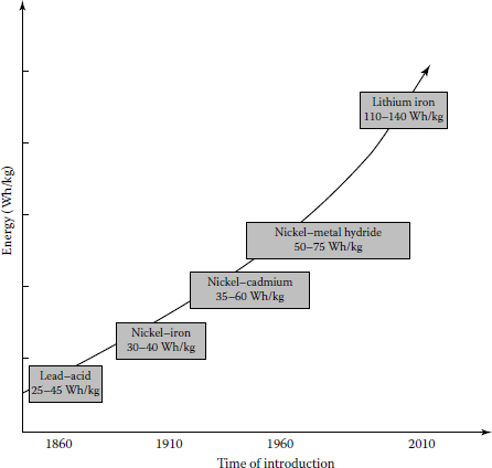
A battery for an electric vehicle has to satisfy certain performance goals that include quick discharge and charge capability, long–cycle life, low cost, recyclability, high specific energy (i.e., the amount of usable energy, measured in watt–hours per kilogram), high energy density (amount of energy stored per unit volume), specific power (defines the potential for acceleration), and the ability to work in extreme heat or cold.
However, at the present time, there is no battery that is available that meets all these criteria. Figure 14.3 shows the trend of exponential improvement in battery performance over the years. Today, a large variety of battery types are being used in electric power systems for grid support applications.
14.4.2 Sodium–Sulfur Batteries
This battery is a high–performance battery, with the electrolyte operating at temperatures of 572°F (300°C). It consists of a liquid (molten) sulfur positive electrode and a molten sodium negative electrode separated by a solid beta alumina ceramic electrode. The electrolyte permits only positive sodium ions to pass through it and combine with sulfur to form sodium polysulfides.
The sodium component of this battery explodes on contact with water, which raises certain safety questions. The materials of the battery have to be capable of withstanding the high internal temperatures they create, as well as freezing and thawing cycles. This battery has a very high specific energy of 110 Wh/kg. During discharge, positive sodium ions flow through the electrolyte and electrons flow in the external circuit of the battery, providing about 2 V. This process is reversible since charging causes sodium polysulfides to release the positive ions back through the electrolyte to recombine as elemental sodium. The Na–S battery cells are efficient (about 89%). This battery system is capable of 6 h of discharge time on a daily basis.
This technology for large–scale applications was perfected in Japan. Presently, there are 190 battery systems in service in Japan, totaling more than 270 MW of capacity with stored energy suitable for 6 h of daily peak shaving. The largest single Na–S battery installation is a 34-MW, 245-MWh system for wind power stabilization in northern Japan. The battery will permit the output of the 51-MW wind farm to be 100% dispatchable during on–peak periods.
According to Roberts [5], in the United States, utilities have applied 9 MW of Na–S batteries for peak shaving, backup power, firming wind capacity, and other applications. Zebra battery is another high–temperature battery and is based on sodium nickel chloride chemistry. It is used for electric transportation applications in Europe. Recently, it is being considered for utility applications as well [5].
14.4.3 Flow Battery Technology
The performance of flow batteries is similar to a hydrogen fuel cell. They use electrolyte liquids flowing through a microporous membrane to generate an electrical charge. They store and release electrical energy through a reversible electrochemical reaction between two liquid electrolytes.
The liquids are separated by an ion-exchange membrane, allowing the electrolytes to flow into and out from the cell through separate manifolds and to be transformed electrochemically within the cell. For their utility applications, various chemistries have been developed. In standby mode, the batteries have a response time of the order of milliseconds to seconds, making them suitable for frequency and voltage support. One of the advantages of such flow battery design is the ability to scale systems independently in terms of power and energy. For example, more cell stacks permit for an increase in power rating, and a greater volume of electrolytes provides for more runtime. Plus, flow batteries operate at ambient (instead of high) temperature levels.
14.4.3.1 Zinc–Bromine Flow Battery
In utility applications, zinc–bromine flow batteries are being used. This battery operates with a solution of zinc bromide salt dissolved in water and stored in tow tanks. The battery is charged or discharged by pumping the electrolytes through a reactor cell.
During the charging cycle, metallic zinc from the electrolyte solution is plated onto the negative electrode surface of the reactor cell. The bromide is converted to bromine at the positive surface of the electrode in the reactor cell and then is stored in the other electrolyte tank as a safe chemically complex oily liquid. During the discharge of the battery, the process is reversed, and the metallic zinc plated on the negative electrode is dissolved in the electrolyte solution and available for the next charge cycle.
In order to create different system ratings and duration times, flow battery manufacturers use modular construction. For example, a zinc bromide flow battery package with a rating of 500 kW for 2 h. Other packages are being applied at utilities with ratings of up to 2.8 MWh packaged in a 53-ft trailer.
14.4.3.2 Vanadium Redox Flow Battery
Another type of flow battery is the vanadium redox battery (VRB). During its charge and discharge cycles, positive hydrogen ions are exchanged between the two electrolyte tanks through a hydrogen-ion permeable polymer membrane. Similar to the zinc-bromine battery, the VRB system’s power and energy ratings are independent of each other [5].
14.4.4 Lithium-Ion Batteries
Among the available battery technologies today, the lithium-ion battery has the greatest applications. It can be applicable in a large variety of shapes and sizes, permitting the battery to efficiently fill the available space, such as a cell phone or a laptop computer. They are also lighter in weight in comparison to other aqueous battery technologies, such as lead–acid batteries. They have the highest power density (110–140 Wh/kg) of all batteries on the commercial market on a per-unit-of-volume basis.
The leading lithium-ion cell design is a combination of lithiated nickel, cobalt, and aluminum oxides, referred to as an NCA cell. There are two lithium-ion designs that are starting to be employed in higher–power utility grid applications: lithium titanate and lithium iron phosphate.
14.4.4.1 Lithium–Titanate Batteries
This battery uses manganese in the cathodes and titanate in the anodes. This chemistry provides for a very stable design with fast charge capability and good performance at low temperatures.
The batteries can be at lower temperatures. They can be discharged to 0% and have a relatively long life. They are used in utility power ancillary service applications (e.g., frequency regulation).
14.4.4.2 Lithium Ion Phosphate Batteries
It is a newer and safer technology in which it is more difficult to release oxygen from the electrode, which reduces the risk of fire in the battery cells. It is more resistant to overcharge when operated in a range of up to 100% state of charge. They are also used in utility power ancillary service applications.
14.4.5 Lead–Acid Batteries
They are the oldest and most mature among all the battery technologies. Because of their large applications, lead–acid batteries have the lowest cost of all battery technologies. This battery operates at an ambient temperature and has an aqueous electrolyte. Even though the lead–acid battery is relatively inexpensive, it is very heavy, with a limited usable energy by weight (specific energy).
A cousin of this battery is the deep-cycle lead–acid battery, now widely used in golf carts and forklifts. The first electric cars built also employed this technology. Lead–acid batteries should not be discharged by more than 80% of their rated capacity or depth of discharge. Exceeding the 80% of the depth discharge shortens the life of the battery. They are inexpensive, readily available, and are highly recyclable, using the elaborate recycling system already in place.
For utility application, a 40-MWh lead–acid battery was installed in the Southern California grid in 1988 to demonstrate the peak shaving capabilities of batteries in a grid application. The application of the battery demonstrated the value of stored energy in the grid; however, the limited cycling capability of lead–acid made the overall economics of the system unacceptable. However, for backup power sources in large power plants, lead–acid batteries are still used as “black start” sources in case of emergencies [5]. Their long life and lower costs make them ideal for applications with low-duty cycles.
Research continues to try to improve these batteries. For example, a lead–acid nonaqueous (gelled lead acid) battery uses an electrolyte paste instead of liquid. These batteries do not have to be mounted in an upright position. There is no electrolyte to spill in the accident. But nonaqueous lead–acid batteries typically do not have a high life cycle and are more expensive than flooded deepcycle lead–acid batteries.
14.4.5.1 Advanced Lead–Acid Batteries
In order to significantly extend the life of lead–acid batteries, carbon is added to the negative electrode. As a result, their life is significantly extended in cycling applications. But lead–acid batteries fail due to sulfation in the negative plate that increases as they are cycled more.
Adding as much as 40% of activated carbon to the negative electrode composition increases the battery’s life up to 2000 cycles. This represents a three-to-four times improvement over the current lead–acid designs. This extended life coupled with lower costs will lead storage developers to revisit lead–acid technology for grid applications.
14.4.6 Nickel–Cadmium Batteries
Nickel–iron (Edison cells) and nickel–cadmium (Ni–Cad) pocket and sintered plate batteries have been in use for many years. Both of these batteries have a specific energy of approximately 25 Wh/lb (55 Wh/kg), which is higher than advanced lead–acid batteries. Both are nontoxic, while Ni–cads are toxic. They can be discharged to 100% of depth of discharge without damage. The biggest obstacle to the utilization of these batteries is their cost. In the past, the Ni–Cad batteries represented a substantial increase in battery power. They are rugged, durable with good cycling capability and a broad discharge range.
In power systems, Ni–Cad batteries have been used in a variety of backup power applications and were chosen to provide “spinning reserve” for a transmission project in Alaska [5]. It involved a 26-MW Ni–Cad battery rated for 15 min, which represents the largest battery in a utility application in North America. Today, they are still being used for utility applications. For example, it is used for the power ramp rate control for smoothing with weak power grids (such as island power systems).
14.5 Operational Problems in Battery Usage
The storage-battery-integrated PV system recovers the energy that would have been lost when voltage is over the limitation value. Since the risk of overvoltage is higher when the reverse power flow is greater, the state of charge of the storage battery should not be full at around noon. Thus, for efficient operation of the storage battery, only part of the surplus power that is greater than the load demand should be charged into the storage battery.
According to Hara et al. [1], the following problems must be considered when operating the storage battery:
- The storage battery must be at a discharge state in the morning to prepare for charging around noon.
- If the lead–acid battery is left in a discharge state, it may deteriorate and shorten the life time.
- The frequency of use of the storage batteries may be varied by the impedance of the distribution line and by a power flow condition.
- There are round-trip energy losses of the storage battery and power conditioning system increases when charging and discharging larger amounts of energy.
14.6 Fuel Cells
They were first developed in 1839 and put to practical use in the 1960s by NASA to generate fuel for electricity needed by the spacecrafts Apollo and Gemini. The stored hydrogen can be converted back to electricity using an open-cycle gas turbine. However, in that case, electrical efficiency tends to be low, even ignoring transportation losses and those associated with converting the electricity to hydrogen in the first place. Fuel cells are quiet, clean, and highly efficient on-site generators of electricity that use the electrochemical process to convert fuel into electricity. This is the reverse electrolysis. It has few moving parts and produces very little waste heat or gas. In addition to generating electricity, fuel cells can also serve as a thermal energy source for water and space heating or for cooling absorption.
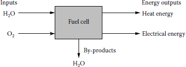
Fuel cells offer an alternative approach and essentially consist of an electrolyte (liquid or solid) membrane sandwiched between two electrodes. A block diagram of a fuel cell is shown in Figure 14.4.
A single fuel cell produces output voltage less than 1 V. Thus, in order to produce higher voltages, fuel cells are stacked on top of each other and are serially connected forming a full cell system. Electrical efficiencies of fuel cells lie between 36% and 60%, according to the type and system configuration. By using conventional heat recovery apparatus, the overall efficiency can be improved to about 85%.
System reforming of liquid hydrocarbons (CnHm) is a potential way of providing hydrogen-rich fuel for fuel cells. This is a preferred method since storage of hydrogen is quite hazardous and expensive. Reformers facilitate a continuous supply of hydrogen without having to use bulky pressurized hydrogen tanks or hydrogen vehicles for distribution. The endothermic reaction that takes place in the reforming process in the presence of a catalyst is
and
Carbon monoxide combines steam to produce more hydrogen through the water gas shift reaction. Figure 14.5 shows the flows and reactions in a fuel cell.

Fuel cells are classified according to the nature of the electrolyte used and the operating temperature, with each type requiring particular materials and fuels. The electrochemical efficiency tends to increase with fuel cell temperature. It is often the nature of the membrane that dictates the operating temperature, and expensive catalysts, such as platinum, may be required to step up the rate of electrochemical reactions. Fuel cells can run using hydrogen, natural gas, methanol, coal, or gasoline.
In addition to this raw fuel of hydrogen, more environmentally friendly fuels, such as biogas, and biomass, may be used. For most fuel cells, such fuels must be transformed into hydrogen using a reformer or coal gasifier. However, high-temperature fuel cells can generally use a fossil fuel (natural gas, coal gas, etc.) directly. Polluting emissions are produced, but since hydrogen is passed over one electrode (anode), hydrogen molecules separate to the cathode where they combine with oxygen to form water. The oxygen supply may be derived from air or as a stored by-product from the water electrolysis (forming hydrogen).
For large-scale utility storage applications, the choice of technology will depend on the ability to use pure hydrogen (electrolyzed from water) as the fuel, the electrical efficiency of conversion, and the load-following capability of the fuel cell, thus providing a degree of regulation from fluctuating wind or other renewable sources. Of the various options available, SO and PEM seem most likely to succeed. The efficiency for conversion of fuel to electricity can be as high as 65%, which is nearly twice as efficient as conventional power plants. Also, small-scale fuel cell plants are just as efficient as the large ones, whether they operate at the full load or not. Because of their modular nature, they can be placed at or near load centers, resulting in savings of transmission network expansion.
A fuel cell power plant is essentially made of three subsystems or sections. In the fuel-processing section, the natural gas or other hydrocarbon fuel is converted to hydrogen-rich fuel. This process is known as a steam catalytic reforming process. This fuel is then fed to the power section, where it reacts with oxygen from the air in a large number of individual fuel cells to produce dc electricity and by-product heat in the form of usable steam or hot water. For a power plant, the number of fuel cells can vary from several hundred (for a 40-kW plant) to several thousand (for a multi-megawatt plant). In the third stage, the dc electricity is converted in the power conditioning subsystem to electric utility-grade ac electricity.
In the power section of fuel cell, which has the electrodes and the electrolyte, two separate electrochemical reactions happen: an oxidation half-reaction, taking place at the anode, and a reduction half-reaction occurring at the cathode. The anode and the cathode are separated from each other by the electrolyte. During the oxidation half-reaction at the anode, gaseous hydrogen produces hydrogen ions, which travel through the ionically conducting membrane to the cathode. At the same time, electrons travel through an external circuit to the cathode. In the reduction halfreaction at the cathode, oxygen supplied from air combines with the hydrogen ions and electrons to form water and excess heat. Hence, the fuel products of the overall reaction are electricity, water, and excess heat.
14.6.1 Types of Fuel Cells
Since the electrolyte defines the key properties, specifically the operating temperature, of the fuel cell, fuel cells are categorized based on their electrolyte type, as described later:
- Polymer electrolyte membrane (PEM)
- Alkaline fuel cell (AFC)
- Phosphoric acid fuel cell (PAFC)
- Molten carbonate fuel cell (MCFC)
- Solid oxide fuel cell (SOFC)
These fuel cells operate at different temperatures, and each of them is best suited to specific applications. Table 14.1 gives a brief comparison of the five cell technologies introduced earlier.
Brief Comparison of Five Fuel Cell Technologies
Type |
Electrolyte |
operating Temperature (°C) |
Applications |
Advantages |
|---|---|---|---|---|
PEM |
Solid organic polymer |
60-90 |
Electric utility, transportation, portable power |
H2 |
Metal oxide (Y2O3/ZrO2) |
700-1000 |
H2, CH4, biogas, etc. Solid electrolyte reduces corrosion, low temperature, quick start-up. Efficiency is 35%-55% | ||
Direct alcohol |
Polymer membrane/ liquid alkaline |
60-120 |
Transportation, portable power |
H2, CH4, biogas, coal gas etc. Its efficiency is 35%-40% |
Alkaline (AFC) |
Aqueous solution of potassium hydroxide soaked in a matrix |
50-90 |
Military, space |
Cathode reaction faster in alkaline electrolyte; thus high performance. It uses H2 as fuel. Efficiency is 50%-60% |
Phosphoric acid (PAFC) |
Liquid phosphoric acid soaked in a matrix |
150-220 |
Electric utility, transportation and heat |
Its efficiency is 45%-55%. Up to 85% efficiency in regeneration of electricity |
Molten carbonate (MCFC) |
Liquid solution of lithium sodium, and/or potassium carbonates soaked in a matrix |
600-750 |
Electric utility |
Higher efficiency, fuel flexibility. inexpensive catalysts. It uses H2, CH4, biogas, coal gas, etc. |
Solid oxide (SOFC) |
Solid zirconium oxide to which a small amount of yttria is added |
600-1000 |
Electric utility |
Higher efficiency, fuel flexibility, inexpensive catalysts. Solid electrolyte advantage like PEM |
14.6.1.1 Polymer Electrolyte Membrane
It is one of a family of fuel cells that are in various stages of development. The electrolyte in a PEM cell is a type of polymer and is usually referred to as a membrane, thus is the name. PEMs are somewhat unusual electrolytes, that is, in the presence of water, which the membrane readily absorbs, the negative ions are rigidly held within their structure. Only the positive (H) ions contained within the membrane are mobile and are free to carry positive charges through the membrane in one direction only, from anode to cathode. At the same time, the organic nature of the PEM structure makes it an electron insulator, forcing it to travel through the outside circuit providing electric power to the load. Each of the two electrodes is made of porous carbon to which very small platinum particles are bonded. The electrodes are slightly porous so that the gases can diffuse through them to reach the catalyst. Also as both platinum and carbon conduct electrons well, they are able to move freely through the electrodes [7]. Chemical reactions that take place inside a PEM fuel cell are the following:
At anode
At cathode
Net reaction
Here, hydrogen gas diffuses through the polymer electrolyte until it meets a platinum particle in the anode. The platinum catalyzes dissociation of the hydrogen molecule into two hydrogen atoms (H) bonded to two neighboring platinum atoms. Only then can each H atom release an electron to form a hydrogen ion (H+), which travels to the same time as the free electron through the other circuit. At the cathode, the oxygen molecule interacts with the hydrogen ion and the electron from the outside circuit to form water. The performance of the PEM fuel cell is limited mainly by the slow rate of the oxygen reduction half-reaction at the cathode, which is 100 times slower than the hydrogen oxidation half-reaction at the anode [7].
14.6.1.2 Phosphoric Acid Fuel Cell
This technology has moved from the laboratory R&D to the first stages of the commercial application. Today, 200-kW plants are available and have been built at more than 70 sites in the United States, Japan, and Europe. Operating at approximately 200°C, the PAFC plant also produces heat for domestic hot water and space heating, and its electrical efficiency is close to 40%. Its high cost is the only thing that stops it from its wide commercial acceptance. At the present time, capital costs of PAFC plant is about $2500-$4000/kW. According to Rahman [7], if it is reduced down to $1000-$1500/kW, this technology may be accepted by the power industry. The chemical reactions that take place at two electrodes are as follows:
At anode
At cathode
14.6.1.3 Molten Carbonate Fuel Cell
This technology is attractive because it offers several potential advantages over PAFC. Carbon monoxide, which positions the PAFC, is indirectly used as a fuel in the MCFC. The higher operating temperature of about 650°C makes the MCFC a better candidate for combined cycle applications whereby the fuel cell exhaust can be used as input to the intake of a gas turbine or the boiler of a steam turbine. The total efficiency can approach 85%. It is just about to enter the commercial market. Capital costs involved are expected to be lower than PAFC. MCFCs are now being tested in full-scale demonstration plants [7]. The chemical reactions that take place inside the cell are the following:
At anode
and
At cathode
14.6.1.4 Solid Oxide Fuel Cell
According to Rahman [7], an SOFC is currently being demonstrated at a 100-kW plant. This technology dictates very significant changes in the structure of the cell. It uses a solid electrolyte, a ceramic material, so the electrolyte does not need to be replenished during the operational life of the cell.
The results of this are simplification in design, operation, and maintenance, as well as having the potential to reduce costs. This offers the potential to reduce costs. This offers the stability and reliability of all solid-state construction and permits higher-temperature operation.
The ceramic makeup of the cell lends itself to cost-effective fabrication techniques. Its tolerance to impure fuel streams makes SOFC systems especially attractive for utilizing H2 and CO from natural gas steam-reforming and coal gasification plants [7]. The chemical reactions that take place inside the cell are as follows:
At anode
and
At cathode
References
1. Hara, R. et al.: Testing the technologies, IEEE Power & Energy Magazine, May/June 2009, 77-85.
2. Gönen, T.: Electric Power Transmission System Engineering: Analysis and Design, CRC Press, Boca Raton, FL, 2009.
3. Gönen, T.: High-temperature superconductors a technical article in McGraw-Hill Encyclopedia of Science & Technology, 7th edn., Vol. 7, 1992, pp. 127-129.
4. Gönen, T, P. M. Anderson, and D. Bowen: Energy and the future, Proceedings of the 1st World Hydrogen Energy Conference, 3(2c), 1977, 55-78.
5. Roberts, B.: Capital grid power, IEEEE Power & Energy Magazine, July/August 2009, 32-41.
6. Jasinski, R.: High-Energy Batteries, Plenium Press, New York, 1967.
7. Rahman, S.: Advanced energy technologies in Electric Power Generation, Transmission, and Distribution, L.L. Grigsby, ed., CRC Press, Boca Raton, FL, 2007.
8. Béguin, F. and E. Frackowiak: Carbons for Electrochemical Energy Storage and Conversion Systems, CRC Press, Boca Raton, FL, 2010.
9. Barak, M.: Electrochemical Power Sources, Peter Peregrinus Ltd., Stevenage, U.K., 1980.
10. Zimmerman, A. H.: Nickel-Hydrogen Batteries, The Aerospace Press, Reston, VA, 2009.
11. Schalkwijk, W. A. and B. Scrosati: Advances in Lithium-Ion Batteries, Kluwer Academic/Plenum Publishers, New York, 2002.
12. Kiehne, H. A.: Battery Technology Handbook, Marcel Dekker, Inc., New York, 1987.
13. Sutton, G. W.: Direct Energy Conversion, McGraw-Hill Book Company, New York, 1966.
14. Gasik, M.: Materials for Fuel Cells, CRC Press, Boca Raton, FL, 2008.
15. Rajalakshmi, N. and K. S. Dhathathreyan: Present Trends in Fuel Cell Technology Development, Nova Science Publishers, Inc., New York, 2008.
16. Barclay, F.: Fuel Cells, Engines and Hydrogen, Wiley, New York, 2006.
17. Ozawa, K.: Lithium Ion Rechargeable Batteries, Wiley-VCH, Weinhein, Germany, 2009.
18. Soo, S. L.: Direct Energy Conversion, Prentice Hall, Englewoods Cliffs, NJ, 1968.
* This chapter is the reprint of chapter 14 of Electrical Machines by T. Gönen, 2nd ed., CRC Press, 2012. Reprinted with the permission of the CRC Press.