Appendix B
Graphic Symbols Used in Distribution System Design
Some of the most commonly used graphic symbols for distribution systems, both in this book and in general usage, are given on the following pages.
Graphic Symbols Used in Distribution System Design
Symbol |
Usage |
|---|---|
|
Polarity markings: Current transformer with instantaneous polarity markings |
|
Potential transformer with instantaneous polarity markings |
|
Power flow direction: One-way |
|
Either way (not simultaneously) |
|
Both ways (simultaneously) |
|
Connection symbols: 2-phase, 3-wire, ungrounded |
|
2-phase, 3-wire, grounded |
|
2-phase, 4-wire |
|
2- phase, 5-wire, grounded |
|
3- phase, 3-wire, delta or mesh |
|
3-phase, 3-wire, delta, grounded |
|
3-phase, 4-wire, delta, ungrounded |
|
3-phase, 4-wire, delta, grounded |
|
3-phase, open-delta |
|
3-phase, open-delta, grounded at the middle point of one winding |
|
3-phase, broken-delta |
|
3-phase, wye or star, ungrounded |
|
3-phase, wye, grounded neutral |
|
3-phase, 4-wire, ungrounded |
|
3-phase, zigzag, ungrounded |
|
3-phase, zigzag, grounded |
|
3-phase, Scott or T |
|
6-phase, double-delta |
|
6-phase, hexagonal (or chordal) |
|
6-phase, star (or diametrical) |
|
6-phase, star, with grounded neutral |
|
6-phase, double zigzag with neutral brought out and grounded |
|
Resistor: Resistor (general) |
|
Tapped resistor |
|
Resistor with adjustable contact |
|
Shunt resistor |
|
Series resistor and path open |
|
Series resistor and path short-circuited |
|
Capacitor: Capacitor (general) |
|
Polarized capacitor |
|
Variable capacitor |
|
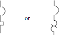
Series capacitor and path open |
|
Series capacitor and path short-circuited |
|
Shunt capacitor |
|
Capacitor bushing for circuit breaker or transformer |
|
Capacitor-bushing potential device |
|
Coupling capacitor potential device |
|
Battery: Battery (general) |
|
Battery with one cell |
|
Battery with multicell |
|
Transmission path (conductor, cable wire): Bus bar, with connection |
|
Conductor or path |
|
2 conductors or paths |
|
3 conductors or paths |
|
n conductors or paths |
|
Crossing of two conductors or paths not connected |
|
Junction |
|
Junction of connected paths |
|
Shielded single conductor |
|
Shielded 5-conductor cable |
|
Shielded 2-conductor cable with conductors separated on the diagram for convenience |
|
3-conductor cable |
|
Grouping of leads: General |
|
Interrupted |
|
Transmission and distribution lines: Telephone line |
|
Cable (or line) underground |
|
Submarine line |
|
Overhead line |
|
Loaded line |
|
Ground: Ground (general) |
|
Switch: Single-throw switch (disconnect switch) |
|
Double-throw switch |
|
Knife switch |
|
Connector: Female contact |
|
Male contact |
|
Separable connectors |
|
Operating coil: Operating coil (general), e.g., reactor |
|
Transformer: Transformer (general) |
|
Adjustable mutual inductor (constant-current transformer) |
|
Single-phase transformer with taps |
|
Single-phase autotransformer |
|
Adjustable |
|
Step-voltage regulator or load-ratio control autotransformer |
|
Step-voltage regulator |
|
Load-ratio control autotransformer |
|
Load-ratio control transformer with taps |
|
Single-phase induction voltage regulator |
|
Triplex induction voltage regulator |
|
3-phase induction voltage regulator |
|
1-phase, 2-winding transformer |
|
3-phase bank of 1-phase, 2-winding transformers with wye–delta connections |
|
Polyphase transformer: Polyphase transformer (general) |
|
1-phase, 3-winding transformer |
|
Current transformer: Current transformer (general) |
|
Bushing-type current transformer |
|
Potential transformers: Potential transformer (general) |
|
Outdoor metering device |
|
Linear coupler |
|
Fuse: Fuse (general) |
|
Fuse (supply side indicated by a thick line) |
|
Isolating fuse switch (HV primary fuse cutout) dry |
|
HV primary fuse cutout, oil |
|
Isolating fuse switch for onload switching |
|
Current limiter (for power cable) |
|
Lightning arrester |
|
Horn gap |
|
Multigap (general) |
|
Circuit breaker: Circuit breaker, air (for dc or ac rated at 1.5 kV or less) |
|
Network protector |
|
HV circuit breaker (for ac rated at above 1.5 kV) |
|
Circuit breaker with thermal-overload device |
|
Circuit breaker with magnetic thermal-overload device |
|
Circuit breaker, drawout type |
|
Rotating machine: Generator (general) |
|
Generator, dc |
|
Generator, ac |
|
Generator, synchronous |
|
Motor (general) |
|
Motor, dc |
|
Motor, ac |
|
Motor, synchronous |