
12.16 Harmonic Amplification
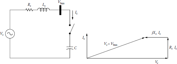
Consider the capacitor switching that is illustrated in Figure 12.10. When the capacitor is switched on, the bus voltage can be expressed as
Vc=V'bus=−jXCZs−jXCVS(12.77a)
or
Vc=V'bus=Vs1−ω21LsC+jω21CRs(12.77b)
At the resonance,
ωr=ω1hr=1√LsC(12.78)
or
hr=ωrω1=1ω1√LsC=√XcXs=√MVAscMvarc(12.79)
Hence, the hth harmonic capacitor voltage (or the capacitor voltage at resonance) can be expressed as
Vc(h)=VsjωCRs=−jVsRs√LsC(12.80a)
or
Vc(h)=jZsRsVs=−jAfVs(12.80b)
where
Zs is the characteristic impedance
ZS=√LSC=√XSXC(12.81)
Af is the amplification factor
Af=ZsRs(12.82)
From Equation 12.80a and b, one can observe that harmonics corresponding or close to the resonant frequency are amplified. The resulting voltages highly exceed the standard voltage rating, causing capacitor damage or fuse blowouts. The amplification factor can also be expressed as
Af=ZsRs=√Ls/CRs=√XsXcRs(12.83a)
or
Af=XsRs×hr(12.83b)
According to ANSI/IEEE Std.18-1992, shunt capacitors can be continuously operated in a harmonic environment provided that [15]
- Reactive power does not exceed 135% of rating
QcQc1=∑h=1h(VhV1)2=∑h=11h(IhI)2≤1.35
- Peak current does not exceed 180% of rated peak
IpeakI1=1+CCF≤1.8
- Peak voltage does not exceed 120% of rated
VpeakV1=1+VCF≤1.2
- RMS voltage does not exceed 110% of rated
VrmsV1=√1+THD2V≤1.1orTHDV≤√0.21=45.8%
Example 12.8
A three-phase wye–wye connected 138/13.8 kV 50 MVA transformer with an impedance of 0.25% + j12% is connected between high- and low-voltage buses. Assume that a wye-connected switched capacitor bank is connected to the low-voltage bus of 13.8 kV and that the capacitor bank is made up of three 4 Mvar capacitors. Assume that at the 138 kV bus, the short-circuit MVA of the external system is 4000 MVA and its X/R ratio is 7. Use a MVA base of 100 MVA and determine the following:
- The impedance bases for the HV and LV sides
- The short-circuit impedance of the power system at the 138 kV bus
- The transformer impedance in per units
- The short-circuit impedance at the 13.8 kV bus in per units
- The X/R ratio and the short-circuit MVA at the 13.8 kV bus in per units
- The reactance of the capacitor per phase in ohms and per units
- The resonant harmonic order
- The characteristic impedance in per units
- The amplification factor
Solution
- Since MVAB(HV) = MVAB(LV) = 100 MVA and kVB(HV) = 138 kV, kVB(LV) = 13.8 kV,
ZB(HV)=kV2B(HV)MVAB(HV)=1382100=190.44Ω
and
ZB(LV)=kV2B(LV)MVAB(LV)=13.82100=1.9044Ω
- Since MVAsc(sys) = 4000 MVA = 40 pu,
Zsc(sys)=140∠tan−17=0.025∠tan−17=0.003536+j0.024749 pu = 0.6734 + j4.7132Ω
- The transformer impedance is
ZT=(0.0025+j0.12)100MVA50MVA=0.005+j0.24pu
- Looking from the 13.8 kV bus,
Zsc=Zsc(sys)+ZT=0.008536 +j0.26475pu = 0.26489∠88.1533∘ pu
- The short-circuit MVA at the 13.8 kV bus is
MVAsc=1Zsc,pu=10.26489=3.775 pu
and the X/R ratio is
(XR)13.8=tan88.1533∘=31.0153
- Since the capacitor bank size is 4 Mvar per phase,
Qc=Mvarc=4 Mvar=0.04pu
so that
Xc=kV2Qc=13.824=47.61Ωper phase = 25pu
- The resonant harmonic order of the resonance between the capacitor bank and system inductance is
hr=frf1=√MVAscMvarc=√3.775pu0.04pu≅9.715
- The characteristic impedance is
Zc=√XscXc=√0.26475×25≅2.573pu
- The amplification factor is
Af=hr(XR)13.8=9.715×31.0153≅301.3
12.17 Resonance
The resonance is defined as an operating condition such that the magnitude of the impedance of the circuit passes through an extremum, that is, maximum or minimum. Series resonance occurs in a series RLC circuit that has equal inductive and capacitive reactances, so that the circuit impedance is low and a small exciting voltage results in a huge current. Similarly, parallel RLC circuit has equal inductive and capacitive reactances, so that circuit impedance is low and a small exciting current develops a large voltage.
The resonance phenomenon, or near-resonance condition, is the cause of the most of the harmonic distortion problems in power systems. Therefore, at the resonance,
XLr=ωrL=XCr=1ωrC
where its resonant frequency is
fr=12π√LC=f1ω1√LC=f1√XCXLHz
where
- f1 is the fundamental frequency
- XC is the capacitor’s reactance at the fundamental frequency
- XL is the inductor’s reactance at the fundamental frequency
Notice that fr is independent of the circuit resistance. The harmonic order of resonant frequency is
hr=frf1=1ω1√LC=√XCXL(12.84)
The resonance can cause nuisance tripping of sensitive electronic loads and high harmonic currents in feeder capacitor banks. In severe cases, capacitors produce audible noise, and they sometimes bulge. Parallel resonance occurs when the power system presents a parallel combination of power system inductance and PF correction capacitors at the nonlinear load. The product of the harmonic impedance and injection current produces high harmonic voltages. Series resonance occurs when the system inductance and capacitors are in series, or nearly in series, with respect to the nonlinear load point. For parallel resonance, the highest voltage distortion is at the nonlinear load. However, for series resonance, the highest distortion is at a remote point, perhaps miles away or on an adjacent feeder served by the same substation transformer.
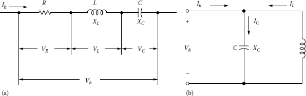
12.17.1 Series Resonance
Consider the series RLC circuit of Figure 12.11a that is made up of RL, XL, and XC at the frequency f. Its equivalent impedance is
Z=R+j(XL−XC)=R+(ωL−1ωC)(12.85)
For any harmonic h,
Z(h)=R+j(h×XL−XCh)(12.86)
so that
|Z(h)|=[R2+(h×XL−XCh)2]1/2(12.87)
At resonance, h = hr and accordingly,
hrXL=XChr=Xr(12.88)
from which
hr=√XCXL(12.89)
and
X2r=XLXC=LC(12.90)
or
Xr=√XLXC=√LC(12.91)
As a result, the impedance of the circuit at the resonance is then purely resistive and is only equal to R. That is,
Z(hr)=R(12.92)
The quality factor Q is
Q=XrR(12.93)
Example 12.9
A series RLC circuit has XL = 0.2 Ω, XC = 1.8 Ω, and Q = 100. Determine the following:
- The harmonic order of the series resonance
- The reactance of the circuit at the resonance
- The value of R
Solution
- Its harmonic order is
hr=√XCXL=√1.80.2=3
- Its circuit reactance at the resonance is
- The value of the resistance is
12.17.2 Parallel Resonance
Consider a parallel RCC circuit of Figure 12.11b that is made up of RL, XL, and XC at a frequency f Its equivalent impedance is
For any harmonic h,
so that
and the impedance is
or
At resonance, h = hr and accordingly,
from which
and
or
Again, the impedance of the circuit is equal to R. That is,
The quality factor Q is
Here, the critical damping takes place at Q = 0.5 or R = 0.5Xr Quality factor determines the sharpness of the frequency response. Q varies considerably by location on the power system. It might be less than 5 on a distribution feeder and more than 30 on the secondary bus of a large step-down transformer.
Example 12.10
For a given parallel RLC circuit having XL = 0.926 Ω, XC = 75 Ω, and Q = 5, determine the following:
- Its harmonic order
- Its circuit reactance at the resonance
- The value of R
Solution
- Its harmonic order is
- Its circuit reactance at the resonance is
- The value of R is
Note that the resistance of the circuit varies with different quality factors.
12.17.3 Effects of Harmonics on the Resonance
In the presence of harmonics, the resonance takes place when the source (or system) reactance XSr is equal to the reactance of the capacitor XCr at the tuned frequency, as follows:
and at an angular resonant frequency of
or
where
- XC1 is the reactance of the capacitor at the fundamental frequency
- Xs1 is the inductive reactance of the source at the fundamental frequency
- Ls1 = Ls is the inductance of the source at the fundamental frequency
- C1 = C is the capacitance of the capacitor at the fundamental frequency
from which the harmonic order hr to cause resonance can be found as
or
Let Xsc = Xs = Xs1, Xc = Xc1 and MVAsc = MVAs, then
so that a capacitor with a reactance of or excites resonance at the hr th harmonic order.
In order to tune a capacitor to a certain harmonic (or designing a capacitor to trap, i.e., to filter a certain harmonic) requires the addition of a reactor. At the tuned harmonic,
or
where its characteristic reactance can be expressed as
The tuned frequency is then
or
Hence, the inductive reactance of the reactor is
or
If ftuned = fr (or htuned = hr), then Equation 12.111b becomes XL = Xs. Also, Equation 12.110a and b becomes
or
Example 12.11
A 34.5 kV three-phase 5.325 Mvar capacitor bank is to be installed at a bus that has a short-circuit MVA of 900 MVA. Investigate the possibility of having a resonance and eliminate it. Determine the following:
- The harmonic order of the resonance.
- The capacitive reactance of the capacitor bank in ohms.
- Design the capacitor bank that will trap the resultant harmonic by adding a reactor in series with the capacitor. Find the required reactor size XL.
- The characteristic reactance.
- Select the filter quality factor as 50 and find the resistance of the reactor.
- The impedance of this resultant series-tuned filter at any harmonic order h.
- The rated filter size.
Solution
- The harmonic order of the resonance due to the interaction between the capacitor bank and the system is
- The capacitive reactance of the capacitor bank is
- The required reactor size is
- The characteristic reactance is
- Since Q = 50,
- The impedance function of the filter is
- The rated filter size is
12.17.4 Practical Examples of Resonance Circuits
Figure 12.12 shows practical examples of possible series and parallel resonant conditions. Figure 12.12a shoes a step-down transformer supplying loads including PF correction capacitors from a bus that has a considerable nonlinear load. Its equivalent circuit is shown in Figure 12.12b. Normally, the harmonic currents generated by the nonlinear load would flow to the utility. Figure 12.12 Practical examples of resonance circuits: (a) series resonance circuit, (b) its equivalent circuit, (c) parallel resonance circuit, and (d) its equivalent circuit.
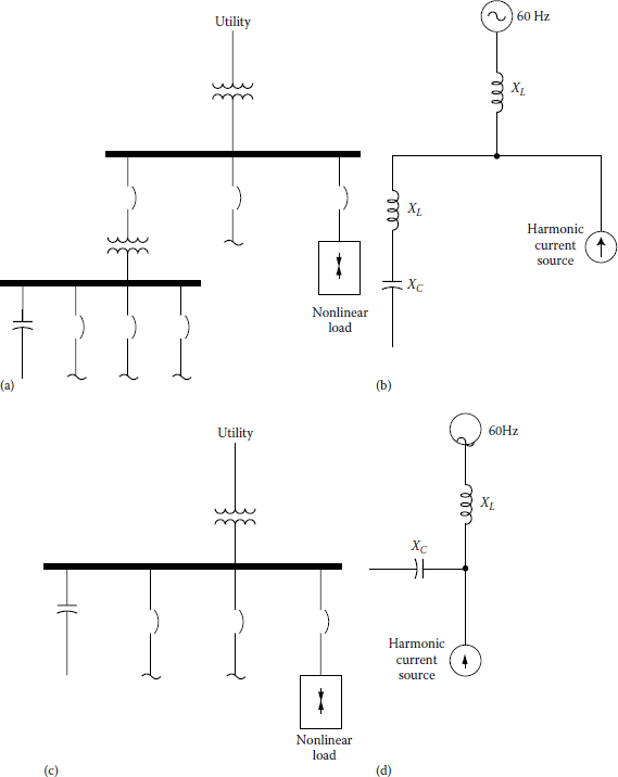
Practical examples of resonance circuits: (a) series resonance circuit, (b) its equivalent circuit, (c) parallel resonance circuit, and (d) its equivalent circuit.
However, if at one of the nonlinear load’s significant harmonic current frequencies (typically, the 5th, 7th, 11th, or 13th harmonic) the step-down transformer’s inductive reactance equals the powerfactor-correction capacitor’s reactance, then the resulting series resonant circuit will attract the harmonic current from the nonlinear load. The additional unexpected harmonic current flow through the transformer and capacitors will cause additional heating and possibly overload.
Figure 12.12c depicts a potentially more troublesome problem, that is, parallel resonance. Its equivalent circuit is shown in Figure 12.12d. In this case, PF correction capacitors are applied to the same voltage bus that feeds significant nonlinear loads.
If the inductive reactance of the upstream transformer equals the capacitive reactance at one of the nonlinear load’s harmonic current frequencies, then parallel resonance takes place. With parallel resonance, high currents can oscillate in the resonance circuit and the voltage bus waveform can be severely distorted.
As discussed before, from the harmonic source’s point of view, at harmonic frequencies, shunt capacitors appear to be in parallel with the equivalent system inductance, as shown in Figure 12.13a and b.
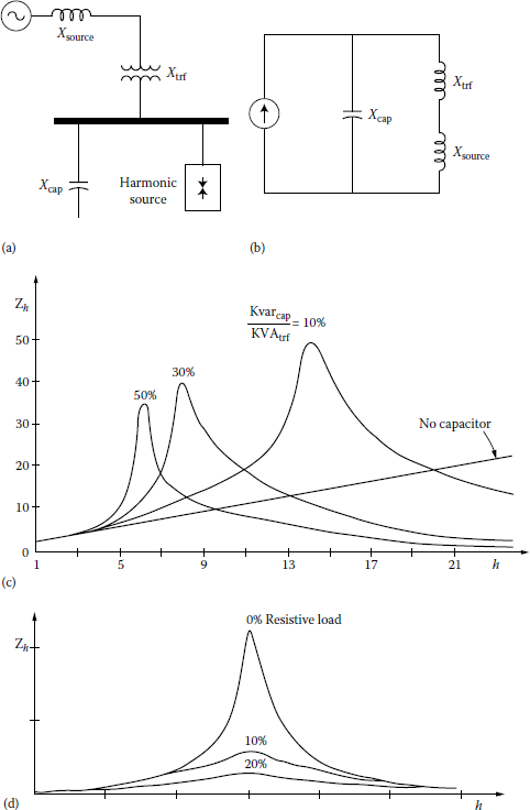
Parallel resonance considerations: (a) a parallel resonance prone system, (b) its equivalent circuit, (c) effects of capacitor sizes, and (d) effects of resistive loads.
At frequencies other than fundamental, the power system generation appears to be short circuit. When there is a parallel resonance situation, that is, at certain frequency where Xc and the total system reactance are equal, the apparent impedance seen by the source harmonic currents becomes very large. Figure 12.13c shows the system frequency response as capacitor size is varied in relation to transformer as well as in the case of having no capacitor.
If one of the peaks lines up with a common harmonic current produced by the load, there will be a much greater voltage drop across the apparent impedance than the case of no capacitors.
However, the alignment of the resonant harmonic with the common source harmonic is not always problematic. Often, the damping provided by resistance of the system is sufficient to prevent any catastrophic voltages or currents, as shown in Figure 12.13d.
As one can see, even a 10% resistance loading has a considerable effect on the peak impedance. Because of this fact, if there is a considerable length of lines or cables between the capacitor bus and the nearest upstream transformer, the resonance will be suppressed.
Since the resistances of lines and cables are significantly large, catastrophic harmonic problems due to capacitors do not appear often on distribution feeders. Therefore, resistive loads will damp resonance and cause a significant reduction in the harmonic distortion.
However, very little damping is achieved if any from motor loads, since they are basically inductive. On the contrary, they may increase distortion by shifting system resonant frequency closer to a significant harmonic. But small fractional-horsepower motors may contribute considerably to damping because of their lower X/R ratios.
The worst resonant conditions take place when capacitors are installed on substation buses where the transformer dominates the system impedance and has a high X/R ratio, the relative resistance is low, and associated parallel resonant impedance peak is very high and sharp. This phenomenon is known to be the cause of the failure in capacitors, transformers, or load equipment.
Example 12.12
A three-phase wye–wye-connected transformer with X = 10% is supplying a 40 MVA load at a lagging PF of 0.9. At the low-voltage bus of 12.47 kV, three-phase wye-connected capacitor bank is to be connected to correct the PF to 0.95. A distribution engineer is asked to investigate the problem, knowing that the short-circuit MVA at the 345 kV bus is 2000 MVA. Use a MVA base of 100 MVA and determine the following:
- The current bases for the HV and LV sides of the transformer in amps
- The impedance bases for the HV and LV sides in ohms
- The short-circuit reactance of the system at the 345 kV bus in per units and ohms
- The short-circuit reactance of the system at the 12.47 kV bus in per units and ohms
- The short-circuit MVA of the system at the 12.47 kV bus in per units and MVA
- The real power of the load at the lagging PF of 0.9 in per units and MW
- The size of the capacitor bank needed to correct the PF to 0.95 lagging in per units and Mvar
- The resonant harmonic order at which the interaction between the capacitor bank and system inductance initiates resonance
- The reactance of each capacitor per phase in per units and ohms
Solution
- Since MVAB(HV) = MVAB(LV) = 100 MVA and kVB(HV) = 345 KV, kVB(LV) = 12.47 kV. The current bases for the HV and LV sides are
and
- The impedance bases for the HV and LV sides are
and
- Since MVAsc(sys) = MVAsc(source) = 2000 MVA = 20 pu,
or
- Since
Looking from the LV bus of 12.47 kV,
or
- The MVAsc at the 12.47 kV bus in per units and MVA are
or
- The real power of load is
- The real size of the three-phase capacitor bank needed to correct the PF is
- Since the capacitor bank is wye connected,
Thus,
or
- The interaction between the capacitance bank and system inductance initiates resonance at
or
12.18 Harmonic Control Solutions
In general, harmonics become a problem if (1) the source of harmonic currents is to large, (2) the system response intensifies one or more harmonics, and (3) the currents’ path is electrically too long, causing either high-voltage distortion or telephone interference.
When these types of problems happen, the following options are the main ones to control the harmonics: (1) decrease the harmonic currents generated by the nonlinear loads; (2) add filters to either get rid of the harmonic currents from the system, supply the harmonic currents locally, or block the currents locally from entering the system; and (3) modify the system frequency response to avoid adverse interaction with harmonic currents.
This can be done by feeder sectionalizing, adding or removing capacitor banks, changing the size of the capacitor banks, adding shunt filters, or adding reactors to detune system away from harmful resonances.
Usually, not much can be done with existing load equipment to substantially reduce its harmonic currents. One exception to these devices is pulse-width modulated (PWM) adjustable-speed drives (ASDs) that change the dc bus capacitor directly from the line. Here, adding a line reactor in series will considerably decrease harmonics as well as provide transient protection benefits.
Transformer connections can also be used to reduce harmonic currents in three-phase systems. For example, delta-connected transformers can block the flow of the zero-sequence triplen harmonics from the line. Also, zigzag and grounding transformers can shunt the triplens off the line.
The filter used can be shunt or series filters. The shunt filter application works by short-circuiting the harmonic currents as close to the source of distortion as practical. It keeps the harmonic currents out of the supply system. It is the most common type of filtering used due to economics and its tendency to smooth the load voltage as well as its elimination of the harmonic current.
The series filter blocks the harmonic currents. It has a parallel-tuned circuit that presents high impedance to the harmonic current. It is not often used since it is difficult to insulate and has very distorted load voltage. It is commonly used in the neutral of a grounded-wye capacitor to block the flow of triplen harmonics while still having a good ground at fundamental frequency.
In addition, it is possible to use active filters. Active filters work by electronically supplying the harmonic component of the current into a nonlinear load.
Furthermore, adverse system responses to harmonics can be modified by using one of the following methods: (1) adding a shunt filter, (2) adding a reactor to detune the system, (3) changing the capacitor size, (4) moving a capacitor to a point on the system with a different short-circuit impedance or higher losses (when adding a capacitor bank results in telephone interference, moving the bank to another branch of the feeder may solve the problem), and (5) removing the capacitor and accepting its consequences may be the best economic choice.
12.18.1 Passive Filters
Passive (or passive tuned) filters are relatively inexpensive, but they have potential for adverse interactions with the power system. They are used either to shunt the harmonic currents off the line or to block their flow between parts of the system by tuning the elements to create a resonance at a selected harmonic frequency. As shown in Figure 12.14, passive filters are made up of inductance, capacitance, and resistance elements. A single-tuned “notch” filter is the most common type of filter since it is often sufficient for the application and inexpensive.
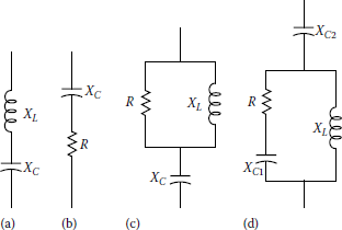
Common passive filter configurations: (a) type I, (b) type II, (c) type III, and (d) type IV.
Figure 12.15 shows typical 480 V single-tuned wye- or delta-connected filters. Such notch filter is series tuned to present low impedance to a specific harmonic current and is connected in shunt with power system. As a result, harmonic currents are diverted from their normal flow path on the line into filter.
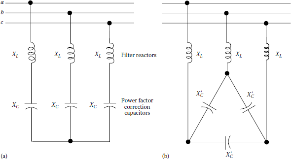
Notch filters provide PF correction in addition to harmonic suppression. As shown in the figure, a typical delta-connected low-voltage capacitor bank converted into a filter by adding an inductance (reactor) in series. The tuned frequency for such combination is selected somewhere below the fifth harmonic (e.g., 4.7) to prevent a parallel resonance at any characteristic harmonic. This is in order to provide a margin of safety in case there is some change in system parameters later. This point represents the notch harmonic, hnotch, and is related to the fundamental frequency reactance X1 by
Here, Xc is the reactance of one leg of the delta rather than the equivalent line-to-neutral capacitive reactance. If line-to-line voltage and three-phase capacitive reactive power are used to calculate Xc, then it should not be divided by 3 in Equation 12.113.
Note that if such filters were tuned exactly to the harmonic, changes in inductance or capacitance with failure or due to changes in temperature might push the parallel resonance higher into the harmonic. As a result, the situation becomes much worse than having no filter.
Because of this, filters are added to the system beginning with the lowest problematic harmonics. Hence, installing a seventh-order harmonic filter usually dictates the installation of a fifth-order harmonic filter.
Also, it is usually a good idea to use capacitors with a higher voltage rating in filter applications because of the voltage rise across the reactor at the fundamental frequency and due to the harmonic loading. In this case, 600 V capacitors are used for a 480 V application.
In general, capacitors on utility distribution systems are connected in wye. It provides a path for the zero-sequence triplen harmonics by changing the neutral connection.
Also, placing a reactor in the neutral of a capacitor is a common way to force the bank to filter only zero-sequence harmonics. It is often used to get rid of telephone interference. Usually, a tapped reactor is inserted into the neutral, and the tap is adjusted according to the harmonic causing the interference to minimize the problem.
Passive filters should always be placed on a bus where Xsc is constant. The parallel resonance will be much lower with standby generation than utility system. Because of this, filters are often removed for standby operation. Furthermore, filters should be designed according to the bus capacity not only for the load.
Note that tuned capacitor banks act as a harmonic filter for the fifth harmonic. They will have to absorb some percentage of the fifth harmonic current from loads within the facility and also will have to absorb fifth harmonic current due to fifth harmonic voltage distortion on the utility supply system. IEEE 519-1992 allows the voltage distortion on the supply system to be as high as 3% at an individual harmonic on medium voltage systems. Thus, this level of fifth harmonic distortion should be assumed for filter design purposes. The general methodology for applying filters is explained in the following steps:
- Only a single-tuned shunt filter designed for the lowest produce frequency is applied at first.
- The voltage distortion level at the low-voltage bus is found out.
- The effectiveness of the filter designed is checked by changing the elements of the filter in conformity with the specified tolerances.
- It is assured that the resulting parallel resonance is not close to a harmonic frequency by reviewing the frequency response characteristics.
- The requirement for having several filters, for example, fifth and seventh or third, fifth, and seventh, is considered in the application.
Consider the single-tuned 480 V notch filter shown in Figure 12.15. Such filter should be tuned slightly below the harmonic frequency of concern. This permits for tolerances in the filter components and prevents the filter from acting as a short circuit for the offending harmonic current. It minimizes the possibility of having dangerous harmonic resonance if the system parameters change and cause the tuning frequently to shift slightly higher.
The actual fundamental frequency compensation provided by a derated capacitor bank is found from
The fundamental frequency current of the capacitor bank is
The equivalent single-phase reactance of the capacitor bank is
The reactance of the filter reactor is found from
where ht is the tuned harmonic. The fundamental frequency current of the filter becomes
Since the filter draws more fundamental current than the capacitor alone, the supplied var compensation is larger than the capacitor rating and is found from
The tuning characteristic of the filter earlier is defined by its quality factor, Q. It is a measure of sharpness of tuning. For such series filter, it is given by
where
- h is the tuned harmonic
- XL = Xreactor is the reactance of filter reactor at fundamental frequency
- R is the series resistance of filter
Usually, the value of R is only the resistance of the inductor that results in a very large value of Q and a very strong filtering. Normally, this is satisfactory for a typical single-filter usage. It is a very economical filter operation due to its small energy consumption.
However, occasionally, it might be required to have some losses to be able to dampen the system response. To achieve this, a resistor is added in parallel with the reactor to create a high-pass filter. In such a case, the quality factor is given by
Here, the larger the Q, the sharper the tuning. It is not economical to operate such filter at the fifth and seventh harmonics because of the amount of losses. However, they are used at the 11th and 13th or higher order of harmonics.
In special cases where tuned capacitor banks are not sufficient to control harmonic current levels, a more complicated filter design may be required. This is often difficult and a more detailed harmonic study will normally be required. Figure 12.16 gives the general procedure for designing these filters.
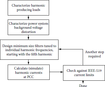
Significant derating of the filters may be required to handle harmonics from the power system. Including the contribution from the power system is part of the process of selecting a minimumsize filter at each tuned frequency. The filter size must be large enough to absorb the power system harmonics.
The design may result in excessive kvar due to the number of filter steps and filter sizes needed for harmonic control. This would result in leading PF and possible overvoltages. In some rare cases, even three or four steps (e.g., 5, 7, 11 or 5, 7, 13) may not be sufficient to control the higher-order harmonic components to the levels specified in IEEE Std. 519-1992.
If the aforementioned concerns result in some unacceptable filter designs, it may be possible to control the harmonics with modifications to nonlinear loads, for example, multiphase configurations or active front ends, or electronically with active filters.
Example 12.13
A 60 Hz 600 V three-phase delta-connected 600 kvar capacitor bank will be used as a part of a single-tuned 480 V filter. The filter will be used for the fifth harmonic of nonlinear loads of an industrial plant. Set the resonant at 4.7 harmonic for a margin of safety. The facility has 500 hp of ASDs connected at 480 V. Design a single-tuned filter and determine the following:
- The actual fundamental frequency compensation provided by a derated capacitor bank.
- The full-load fundamental frequency current of the capacitor bank.
- The wye equivalent single-phase reactance of the capacitor bank.
- The reactance of the serially connected filter reactor.
- The full-load current of the filter.
- The reactive power supplied to the filter.
- Compare the capacitor ratings with the standard capacitor limits that are given in IEEE Std. 18-1980. Are they within the limits?
Solution
- The full-load fundamental frequency current of the capacitor bank is
- The full-load fundamental frequency current of the capacitor bank is
- The wye equivalent single-phase reactance of the capacitor bank is
- The reactance of the serially connected filter reactor is
- The full-load current of the filter is
- The reactive power supplied to the filter is
- Table 12.12 shows the design spreadsheet of the filter. The standard capacitor limits that are given in IEEE Std. 18-1080 are shown at the bottom of the table. As one can see, the capacitor ratings are within the limits of the standard.
Harmonic Filter Design Spreadsheet for Example 12.13
System Information
Filter specification: 5th
Power system frequency: 60 Hz
Capacitor bank rating: 600 kvar
Capacitor rating: 600 V
Rated bank current: 577 A
60 Hz
Nominal bus voltage: 480 V
Derated capacitor: 384 kvar
Capacitor current (actual): 461.9 A
Total harmonic load: 500 kVA
Filter tuning harmonic: 4.7th
Filter tuning frequency: 282 Hz
Cap impedance (wye equivalent): 0.6000 Ω
Cap value (wye equivalent): 4421.0 qF
Reactor impedance: 0.0272 Ω
Reactor rating: 0.0272 mH
Filter full-load current (actual): 483.8 A
Supplied compensation: 402 kvar
Filter full-load current (rated): 604.7 A
Utility side VA: 3.00%
Transformer nameplate: 1500 kVA
(Rating and impedance): 6.00%
(Utility harmonic voltage source)
Load harmonic current: 35.00% fund
Utility harmonic current: 134.5 A
Load harmonic current: 210.5 A
A Max total harmonic current: 345.0 A
Capacitor Duty Calculations
Filter rms current: 594.2 A
Fundamental cap voltage: 502.8 V
Harmonic cap voltage: 71.7 V
Maximum peak voltage: 574.5 V
RMS capacitor voltage: 507.8 V
Maximum peak current: 828.8 A
Capacitor Limits (IEEE Std. 18-1980)
Filter Configuration
Limit (%)
Actual (%)
Three delta-connected 600 kvar and 600 V rated capacitors connected over three XL = 0.0272 Ω reactors to a 480 V bus
Peak Voltage
120
96
Current
180
103
Kvar
135
87
RMS voltage
110
85
Filter Reactor Design Specifications
Reactor impedance: 0.0272 Ω
Reactor rating: 0.0720 mH
Fundamental current: 483.8 A
Harmonic current: 345.0 A
12.18.2 Active Filters
Active filtering is a new technology that uses intelligent circuits to measure harmonics and take corrective actions. Active filters use either the phase-cancellation principle by injecting equal but opposite harmonics, or they inject/absorb current bursts to hold the voltage waveform within an acceptable tolerance of sinusoidal.
They are much more expensive than passive filters, but they have some great advantages. For example, they do not resonate with the system. Because of this advantage, they can be used in very difficult parallel resonance spots where passive filters cannot operate successfully.
They are very useful for large distorting loads fed from somewhat weak points on the power system. Also, they can be used for more than one harmonics at a time and are useful against other power quality problems such as flickers.
The main idea is to replace the missing sine wave portion in a nonlinear load. In an active filter, an electronic control monitors the line voltage and/or current, switching the power electronics very precisely to track the load current or voltage and force it to be sinusoidal. Either an inductor is used to store up current to be injected into the system at the appropriate instant or a capacitor is used instead. As a result, the load current is distorted as demanded by the nonlinear load but the current seen by the system is much more sinusoidal. Active filters correct both harmonics and PF of the load.
12.19 Harmonic Filter Design
As previously discussed, in order to tune a capacitor to a certain harmonic (or designing a capacitor to trap, i.e., to filter a certain harmonic), it requires the addition of a reactor. At the tuned harmonic htuned,
or
so that
Thus, the tuned frequency is
and the tuning order is
The inductive reactance of the reactor is
Capacitors are sensitive to peak voltages. Because of this, they need to be able to withstand the total peak voltage across it. Thus, a capacitor has to have a voltage rating that is equal to the algebraic sum of the fundamental and tuned harmonic voltages. That is,
or
But, a capacitor tuned to a particular harmonic may absorb other harmonics as well. Accordingly, a capacitor should have a voltage rating of
even though its rms voltage is
The reactive power absorbed by the capacitor bank can be expressed as
and the reactive power delivered by the capacitor bank is
12.19.1 Series-Tuned Filters
A series-tuned filter is basically a capacitor designed to trap a certain harmonic by the addition of a reactor having XL = XC at the tuned frequency ftuned. Steps of designing a series-tuned filter to the htuned harmonic include the following:
- Estimate the capacitor size QC in Mvar to be equal to the reactive power requirement of the harmonic source.
- Determine the reactance of the capacitor from
- Find the size of the reactor that is necessary to trap the ht harmonic from
- Find out the resistance of the reactor from
where Q is the quality factor of the filter, 30 < Q < 100.
- Find out the characteristic reactance of the filter from
- Determine the filter size from
- Give the impedance function of the filter at any harmonic h:
so that
- Calculate the ratio of the fundamental component of the voltage across the capacitor to the fundamental component of the voltage at the bus from
- Calculate the ratio of the capacitor voltage at the tuned frequency to the bus voltage at the tuned frequency from
where
and
- Determine the bus voltage from
Example 12.14
Assume that a series-tuned filter is tuned to the ninth harmonic. If XC = 324 Ω, determine the following:
- The reactor size of the filter
- The characteristic reactance of the filter
- The size of the reactor resistance, if the quality factor is 100
Solution
- The reactor size is
- The characteristic reactance of the filter is
- The size of the reactor resistance is
Example 12.15
Suppose that for a 34.5 kV series-tuned filter XC = 676 Ω, XL = 4 Ω, and R = 1.3 Ω, determine the following:
- The tuning order of the filter.
- The quality factor of the filter.
- The reactive power delivered by the capacitor bank.
- The rated size of the filter.
- If the filter is used to suppress the resonance at the 13th harmonic, find the short-circuit MVA at the filter’s location.
Solution
- The tuning order of the filter is
- The quality factor of the filter is
- The reactive power delivered by the capacitor bank is
- The rated size of the filter is
- The short-circuit MVA is
12.19.2 Second-Order Damped Filters
The steps of designing a second-order damped filter tuned to the htuned harmonic include the following:
- Decide the capacitor size QC in Mvar for the reactive power requirement of a harmonic source.
- Calculate the reactance of the capacitor from
- Find the size of the reactor that is necessary to trap the htuned harmonic from
- Determine the size of the resistor bank from
where Q is the quality factor of the filter, 0.5 < Q < 5.
- Find the characteristic reactance of the filter from
- Determine the rated filter size from
- Give the impedance function of the filter at any harmonic h:
or
- Calculate the current of the reactor from
or
- Determine the current of the resistor from
or
- Find the power loss in the resistor from
or
Example 12.16
Assume that a second-order damped filter is to be tuned to htuned ≥ 13. If XC = 2.5 Ω, determine the following:
- The size of the reactor
- The characteristic reactance
- The sizes of the resistor bank for the quality factors of 0.5 and 5
Solution
- The size of the reactor is
- The characteristic reactance is
- The sizes of the reactor bank are
Example 12.17
A 34.5 kV 6 Mvar capacitor bank is being used as a second-order damped filter tuned to htuned ≥ 5. Determine the following:
- The size of the capacitor reactance of the filter
- The size of the filter
- The characteristic reactance of the filter
- The size of the resistor bank for the quality factors of 0.5, 2, 3, 5
- The rated filter size
Solution
- The size of the capacitor reactance of the filter is
- The reactor size of the filter is
- The sizes of the resistor bank are
- The reactor size is
where
12.20 Load Modeling in the Presence of Harmonics
12.20.1 Impedance in the Presence of Harmonics
The impedance of an inductive element, which has resistance of R and reactance of XL = 2πfL, is normally expressed as
at the fundamental frequency. However, in the presence of harmonics, the impedance of such element becomes
where h is the harmonic order.
Similarly, a capacitive element has a reactance of XC = 1/(2πfC) at the fundamental frequency. In the presence of harmonics, the reactance becomes
12.20.2 Skin Effect
As the frequency increases, conductor current concentrates toward the surface, so that the ac resistance increases and the internal inductance decreases. Therefore, in modeling the power system components for a harmonics study, the impact of skin effects must be taken into account in determining the impedances of individual system components. Some researches represent passive loads at a harmonic order of h as
where
- R is the load resistance at the fundamental frequency
- X is the load reactance at the fundamental frequency
- h is the harmonic order
Note that some other researches use a factor of 0.6 instead of as the weighting coefficient for frequency dependence of the resistive component. Taking skin effect into account in the presence of harmonics, the impedance of a transformer is given as
Similarly, the impedance of a generator is given as
The impedance of a transmission line is represented by
12.20.3 Load Models
In harmonics studies involving mainly a transmission network, the loads are usually made up of equivalent parts of the distribution network, specified by the consumption of active and reactive power. Normally, a parallel model is used and the equivalent load impedance is represented by
where
There are many variations of this parallel form of load representation. For example, some researches suggest to use
and
where P and Q are fundamental frequency active and reactive powers, respectively.
Due to difficulties involved, the power electronic loads are often left open-circuited when calculating harmonic impedances. However, their effective harmonic impedances need to be considered when the power ratings are relatively high, such as arc furnaces and aluminum smelters. An alternative approach to explicit load representation is the use of empirical models derived from measurements [14].
Example 12.18
A three-phase purely resistive load of 50 kW is being supplied directly from a 60 Hz threephase 480 V bus. At the time of measuring, the load was using 48 kW and the voltage waveform had 12 V of negative-sequence fifth harmonic and 9 V of positive-sequence seventh harmonic. Assuming that the load resistance varies with the square root of the harmonic order h, determine the following:
- The values of the load resistance
- The components of the load current
- The THD index for the voltage
- The THD index for the current
- The TDD index for current
Solution
- The values of the load resistance are
- The components of the load are
- The THD index for the voltage is
- The THD index for the current is
- The TDD index for the current is
Problems
- 12.1 The harmonic currents of a transformer are given as 1.00, 0.33, 0.20, 0.14, 0.11, 0.09, 0.08, 0.07, 0.06, 0.05, and 0.05 in pu A for the harmonic order of 1, 3, 5, 7, 9, 11, 13, 15, 17, 19, and 21, respectively. Also assume that the eddy current loss factor is 10%. Based on ANSI/IEEE Std.C75.110, determine the following:
- The K-factor of the transformer
- The transformer derating based on the standard
- 12.2 Consider an industrial load bus where the transformer impedance is dominant. If a parallel resonance condition is created by its 1800 kVA transformer, with 5% impedance, and 400 kvar PF correction capacitor bank, determine:
- The resonant harmonic
- The approximate or parallel resonant frequency
- 12.3 A 60 HZ 480 V three-phase delta-connected 500 kvar capacitor bank will be used as a part of a single-tuned 480 V filter. The filter will be used for the fifth harmonic of nonlinear loads of an industrial plant. Set the resonant frequency at 4.7 harmonic for a margin of safety. The facility has 500 hp of ASDs connected to 480 V. Design a single-tuned filter and determine the following:
- The actual fundamental frequency compensation provided by a derated capacitor bank
- The full-load fundamental frequency current of the capacitor bank
- 12.4 An electric car battery charger is 5 kW and that is supplied by a 5 kVA, 2400/240 V 60 Hz single-phase transformer with an impedance of 0.021 + j0.008 pu ohms. Assume that everything else is the same as before. Determine the following:
- The low-voltage side base impedance of the transformer.
- The per unit impedance of the service drop line.
- The value of the ratio Isc/IL.
- Based on IEEE Std. 519-1992, find the maximum limits of odd current harmonics at the meter in steady-state operation, expressed in percent of the fundamental load current IL.
- 12.5 Based on the output of a harmonic analyzer, a nonlinear load current has rms total of 10.5 A, total odd harmonics of 115.2%, total even harmonics of 13.8%, and a THD of 128.3%. Its total odd harmonic distribution is given in Table P12.5. Consider the current waveform and spectrum of a distorted current and determine the following:
- The fundamental current in amps
- The 300 Hz harmonic current in amps
- The 660 Hz harmonic current in amps
- The crest factor
- 12.6 Based on the output of harmonic analyzer, a nonlinear load has a total rms current of 43.3 A. It also has 22.8, 12, 2.20, and 2.48 A for the third, fifth, seventh, and ninth harmonic currents, respectively. Here, the instrument used has been programmed to present the resulting data in amps rather than in percentages. Based on the given information, determine the following:
- The fundamental current in amps
- The amounts of the third, fifth, seventh, and ninth harmonic currents in percentages
- The amount of the THD
- 12.7 The illumination of a large office building is being provided by fluorescent lighting with electronic ballasts. A line current measurement of a branch circuit serving exclusively such fluorescent lighting has been made by using a harmonic analyzer. The output of the harmonic analyzer is a phase current waveform and spectrum of current supplying such electronic power loads. For a 60 Hz 15.2 A fundamental rms current, it is observed from the spectrum that there is 100% fundamental odd triplen harmonics of 19.9%, 2.4%, 0.4%, 0.1%, and 0.1% for the 3rd, 9th, 15th, 21st, and 27th order, respectively. It is assumed that loads on the three phases are balanced and all have the same characteristic, determine the following:
- The approximate value of the rms phase current in per units
- The approximate value of the rms neutral current in per units
- The ratio of the neutral current to the phase current
- 12.8 In an office building, a line current measurement of a branch circuit serving some nonlinear loads has been made by using a harmonic analyzer. The output of the analyzer is phase current waveform and spectrum of current supplying such electronic loads. For a 60 Hz 105 A fundamental rms current, it is observed from the spectrum that there is 100% fundamental and odd triplen harmonics of 70.4%, 3.8%, 1.2%, 1.1%, 0.3%, and 0.5% for 3rd, 9th, 15th, 21st, 27th, and 33rd order, respectively. Assume that loads on the three phases are balanced and all have the same characteristic, determine the following:
- The approximate value of the rms phase current in per units
- The approximate value of the rms neutral current in per units
- The ratio of the neutral current to the phase current
- 12.9 In a large office building, there are 500 combinations of personal computers and printers. The harmonic spectrum of the total current shows the third harmonic (70%), followed by the fifth (60%), seventh (40%), and ninth (22%). Assume that each PC’s fundamental current is 1 A. If a 500 kVA, 12.47 kV/480 V transformer supplies the building at 0.95 lagging PF, determine the following:
- The total rms load current
- The total fundamental load current
- The third harmonic load current
- The fifth harmonic load current
- The seventh harmonic load current
- The ninth harmonic load current
- The TDD index of the load
- The transformer neutral current
- 12.10 A 4.16 kV three-phase feeder is supplying a purely resistive load of 4500 kVA. It has been determined that there are 80 V of zero-sequence third harmonic and 180 V of negativesequence fifth harmonic. Determine the following:
- The total voltage distortion.
- Is the THD below the IEEE Std. 519-1992 for the 4.16-kV distribution system?
- 12.11 According to ANSI 368 Std., telephone interference from a 4.16 kV distribution system is unlikely to occur when I · T index is below 10,000. Consider the load given in Problem 12.10 and assume that the TIF weightings for the fundamental, the third, and the fifth harmonics are 0.5, 30, and 225, respectively. Determine the following:
- The I1, I2,I3, and I5 currents in amps.
- The indices of I · T, I · T2, I · T3, and I · T5.
- The total I · T index.
- Is the total I · T · T index below the ANSI 368 Std. limit?
- The total TIF index.
- 12.12 Repeat Example 12.3 if the load is 6,300 kVA.
- 12.13 A three-phase wye–wye-connected 230/13.8 kV 80 MVA transformer with X = 19% is supplying a 50 MVA load at a lagging PF of 0.9. At the low-voltage bus of 13.8 kV, a threephase wye-connected capacitor bank is to be connected to correct the PF to 0.95. A distribution engineer is asked to investigate the problem, knowing that the short-circuit MVA at the 230 kV bus is 1600 MVA. Use a MVA base of 100 MVA and determine the following:
- The current bases for the HV and LV sides in amps
- The impedance bases for the HV and LV sides in ohms
- The short-circuit reactance of the system at the 230 kV bus in per units and ohms
- The short-circuit reactance of the system at the 13.8 kV bus in per units and ohms
- The short-circuit MVA of the system at the 13.8 kV bus in per units and MVA
- The real power of the load at the lagging PF of 0.9 in per units and MW
- The size of the capacitor bank needed to correct the PF to 0.95 lagging in per units and Mvar
- The reactance of each capacitor per phase in per units and ohms
- The resonant harmonic at which the interaction between the capacitor bank and system inductance initiates resonance
- The reactance of each capacitor in per units and ohms, if the capacitor bank is connected in delta
- 12.14 Verify Equation 12.82 by derivation.
- 12.15 A three-phase 13.8 kV 10 MVA capacitor bank is causing a bus voltage increase of 800 V when switched on. Determine the following:
- The increase in bus voltage in per units
- The resonant harmonic
- The harmonic frequency at the resonance
- 12.16 A three-phase wye–wye-connected 115/12.47 kV 60 MVA transformer with an impedance 0. 3% + j13% is connected between high-and low-voltage buses. Assume that a wye-connected switched capacitor bank is connected to the low-voltage bus of 12.47 kV and that the capacitor bank is made up of three 3 Mvar. At the 115 kV bus, the short-circuit MVA of the external system is 2000 MVA and its X/R ratio is 6.5. Use MVA base of 100 MVA and determine the following:
- The impedance bases for the HV and LV sides
- The short-circuit impedance of the power system at the 115 kV bus
- The transformer impedance in per units
- The short-circuit impedance at the 12.47 kV bus in per units
- The X/R ratio and the short-circuit MVA at the 12.47 kV bus in per units
- The reactance of the capacitor per phase in ohms and per units
- The resonant harmonic order
- The characteristic impedance in per units
- The amplification factor
- 12.17 A series-tuned filter is tuned to the 11th harmonic. If XC = 605 O, determine the following:
- The reactor size of the filter
- The characteristic reactance of the filter
- The size of the reactor resistance, if the filter quality factor is 90
- 12.18 Consider a 34.5 kV series-tuned filter that has XC = 423.5 O, XL = 3.5 O, and, determine the following:
- The tuning order of the filter.
- The quality factor of the filter.
- The reactive power delivered by the capacitor bank.
- The rated size of the filter.
- If the filter is used to suppress the resonance at the 11th harmonic, determine the shortcircuit MVA at the filter’s location.
- 12.19 Assume that a second-order damped filter is to be tuned to htuned ≥ 15. If XC = 1.8 O, determine the following:
- The size of the reactor
- The characteristic reactance
- The size of the resistor bank for the quality factors of 0.5 and 5
- 12.20 A 12.47 kV 3 Mvar capacitor bank is being tuned to htuned ≥ 9. Determine the following:
- The capacitor reactance size
- The reactor size
- The characteristic reactance
- The resistor bank sizes for the quality factors of 0.5, 2, 3, 5
- The rated filter size
- 12.21 Consider a single-phase power line, with an impedance of 1 + j4 ohms, connected to a 7.2 kV power source. Assume that a fifth harmonic current source of 100 A is connected to the line and that the line resistance is constant at the fifth harmonic current level. Determine the following:
- The equivalent circuit of the system
- The magnitude of the line impedance
- The voltage drop of the line
- The percent voltage drop of the line
- 12.22 Consider Problem 12.21 and assume that there is a capacitor connected just before the harmonic current source. Its capacitive reactance is 260 Ω. Determine the following:
- The reactive power of the capacitor
- The capacitive reactance of the capacitor at the fifth harmonic
- The resonant harmonic
The Output of the Harmonic Analyzer
Percentage (%) |
|
|---|---|
Fundamental |
100.0 |
3rd |
70.4 |
5th |
28.8 |
7th |
0.7 |
9th |
3.8 |
11th |
1.5 |
13th |
3.0 |
15th |
1.2 |
17th |
2.1 |
19th |
0.9 |
21st |
1.1 |
23rd |
0.4 |
25th |
0.3 |
27th |
0.3 |
29th |
0.4 |
31st |
0.3 |
33rd |
0.5 |
References
1. Gönen, T. and A. A. Mahmoud: Bibliography of power system harmonics, Part I. IEEE Trans. Power Appar. Syst., PAS-103(9), September 1984, 2460–2469.
2. Gönen, T. and A. A. Mahmoud: Bibliography of power system harmonics, Part II. IEEE Trans. Power Appar. Syst., PAS-103(9), September 1984, 2470–2479.
3. Heydt, G. T.: Electric Power Quality, 1st Ed., Stars in a Circle Publications, West LaFayatte, IN, 1991.
4. Dugan, C. R., M. F. McGranaghan, and H. W. Beaty: Electric Power Quality, McGraw-Hill, New York, 1996.
5. Recommended Practice for Establishing Transformer Capability When Supplying Nonsinusoidal Load Currents, ANSI/IEEE C57.110-1986, New York, 1986.
6. IEEE Tutorial Course: Power System Harmonics, 84 EHO221-2-PWR, IEEE Power Engineering Society, New York, 1984.
7. IEEE Recommended Practices and Requirements for Harmonic Control in Electric Power Systems, IEEE Std. 519-1992, IEEE, New York, 1993.
8. IEEE Guide for Applying Harmonic Limits on Power Systems, Power System Harmonics Committee Report, IEEE Power Engineering Society, New York, 1994.
9. Arrilaga, J.: Power System Harmonics, Wiley, New York, 1985.
10. Bollen, M. H. J.: Understanding Power Quality Problems: Voltage Sags and Interruptions, IEEE Press, New York, 2000.
11. Kennedy, B. W.: Power Quality Primer, McGraw-Hill, New York, 2000.
12. Porter, G. and J. A. Van Sciver: Power Quality Solutions: Case Studies for Trouble Shooters, Fairmont Press, Lilburn, GA, 1998.
13. Shepherd, W. and P. Zand: Energy Flow and Power Factor in Nonsinusoidal Circuits, Cambridge University Press, Cambridge, U.K., 1979.
14. Arrilaga, J., N. R. Watson, and S. Chen: Power System Quality Assessment, Wiley, New York, 2000.
15. Wakileh, G. J.: Power Systems Harmonics, Springer-Verlag, Berlin, Germany, 2001.
16. National Technical Information Service: Federal Information Processing Standards Publication 94: Guidelines on Electric Power for ADP Installations.
17. Information Technology Industry Council: ITI curve Application Note, available at http://www.itic.org/iss-pol/techdocs/curve.Pdf.