
Chapter 21. Interaction Techniques
21.1. Introduction
While human-computer interaction is a field in itself, certain interaction techniques use a substantial amount of the mathematics of transformations, and therefore are more suitable for a book like ours than one that concentrates on the design of the interaction and the human factors associated with that design. We illustrate these ideas with a multitouch interface for 2D manipulation, and three 3D manipulators: the arcball, trackball, and Unicam. In each case we discuss the mathematics, but also the design choices made in creating the interaction technique.
We begin with a discussion of some basic ideas in interaction that everyone in graphics should know. Section 21.3 discusses an implementation of a simple multitouch photo-sorting application. We then discuss 3D transformation interfaces, both for rotating objects and for adjusting the camera in a scene. We conclude with some guidelines and example interfaces that demonstrate particularly useful ideas.
21.2. User Interfaces and Computer Graphics
Despite the advances in games and other technologies, the single biggest user of computer graphics is still and will continue to be the graphical user interface (GUI), by almost any measure except the number of pixels drawn, where games (or video display) undoubtedly dominate. This GUI is increasingly a combination of the WIMP (windows, icons, menus, pointers) GUI and post-WIMP developments like multitouch interfaces and 3D gestural interfaces.
There are two reasons for this. The first is the commoditization of hardware due to Moore’s law and the superb engineering of interaction devices, displays, and wireless technologies. The second reason is the economics of computing: While it was once true that computers were expensive and users were not, the opposite is now true—processors are so cheap that an entry-level computer costs less than a week’s salary at minimum wage. In this economic environment, it makes sense to save time where it’s expensive—the user!—rather than where it’s cheap.
The discovery of an effective interface model—the WIMP GUI—to replace the cryptic mechanisms of the past not only enlarged the market for computing, but in doing so, enabled further progress by providing processor makers with large economies of scale: The cost of developing a new machine could be amortized over many more users.
While the framework provided by a GUI design like WIMP is a wonderful stepping stone, developing a good user interface is still extremely difficult. Although trial and error have their place in the exploration of possible designs, effective designs need testing and refinement, and having a model of the entire process of interaction, from the machine-dependent side (the pixel position of a pointer, filtering of pointer tracks to remove noise, etc.) to the human (the user’s mental state, or his or her goals and sense of progress toward those goals, as in “I’m trying to move this paragraph, and I’ve succeeded in selecting it ...”) is critical to both of these. The study of effective interaction is the field of human-computer interaction (HCI) [PRS02]. HCI is intensely multidisciplinary, involving hardware and software engineering, computer and mathematical sciences, design arts, ergonomics, and perhaps most important, human sciences (perception, cognition, and increasingly, social interaction), not to mention cultural and accessibility issues. It is, first and foremost, a design discipline, one where results are subject to experimentation and validation.
Such usability testing is surprisingly complex. Consider the problem of comparing two interface choices: one easy to learn but with limited expressive power, the other with great expressive power but difficult to learn. A good example is the choice of function keys versus a mouse for selecting menu items. Function keys are easy to learn, while using a mouse effectively requires several days of training. (If you doubt this, try using your mouse with your other hand for an hour. Even knowing all about the mouse, you’ll soon find it’s annoying you more than helping you.) Which is better? The function keys or the mouse? The answer is, naturally, that it depends: If you’re going to be using the mouse for lots of other things as well, the eventual benefit may be large enough to make it worth learning (and the immediate benefit may be large enough to motivate you to do so). If doing this particular task is a one-time-only event, then the simpler interface is almost certainly better. As a concrete example, Adobe’s Photoshop has an enormous user interface that takes quite a long time to learn completely. As a novice user, it sometimes seems that everything you do makes the picture worse! But when used with a pen and tablet (for which much of the design is optimized), the interface supports such a wide array of operations relatively smoothly that it’s become the dominant tool in its domain. By contrast, simpler image-editing programs like the Microsoft Office Picture Manager are easy to learn and use instantly, but this is in part because they support such a small range of operations. To be clear: A complex interface may be a necessity for expressive power, but not every complex interface is a good one. A common evolution pattern is accretion, in which new features are added to a program over time, each one added in the place that seems most convenient at that moment. The end result is a complex interface in which there’s little logical organization at all, and the resultant program may be difficult to use, even for experts who use it every day.
These examples, though simple, make it clear that the testing of a user interface may depend on a larger context—not just the interaction process or device, but the entire user experience, which bundles the GUI together with its interaction and with the particular software functionality, and perhaps even with the context of use (shopping mall versus automobile versus office).
Before we leave the topic of complexity versus learnability, there are two more relevant aspects of GUIs. First, there’s a general principle that recognition is faster than recall: It’s easier to recognize a “yield” sign in the United States than to say whether its triangular shape points up or down, for instance. In the case of GUIs, this means that using familiar names and icons can help a new user make sense of a new interface almost instantly. For the same reason, placing menu items in expected places is generally a good idea. Second, you should, if possible, design a gentle slope interface [HKS+97], one in which it’s easy to do something right away, but in which there’s a smooth transition from novice to power user. Menus that display, next to each item, a keystroke that invokes that menu item are an example. Things like tool trays, which are buttons that can either be clicked (to invoke a standard operation) or be expanded into multiple buttons (to allow selection of closely related operations), provide easy access to richer functionality. (For example, a drawing program might have a button that selects line-drawing mode. When its tool tray is expanded, there might be options to draw solid, dotted, or dashed lines.) Such gentle slope interfaces provide a pathway between ease of initial use and ease of expert use.
As with software engineering, there are multiple design approaches that all share a common trait of needing to be user-centered, that is, to know the client and the domain. Two dominant ones are (a) a modified waterfall model1 for software engineering, and (b) rapid prototyping, in which the evolving interface is always functional, but is gradually adapted from minimal function (clicking a button generates a “button clicked” message) to sophisticated interaction sequences. Some mixture of both of these processes is typical in the development of new kinds of interaction.
1. In the waterfall model, requirements determine design; the design determines the implementation. After implementation, the system is verified, and then maintained. Each step is completed before the next. In the modified waterfall, there is substantial feedback at all levels.
Abstraction boundaries can help you develop an interface effectively. These boundaries are the places where substitutions may make sense, whereas within a particular layer, there may be dependencies that make substitution less feasible. For instance, we may have a design in which a mouse is used to point at various things; substituting a pen for the mouse’s pointing functionality is often reasonable (although if clicking or double-clicking is part of the process, then the substitution may have to be more complex, with pen taps replacing button clicks). Replacing the pen with a Wiimote, or with your hand in a Kinect system, is similarly reasonable, although with each substitution, the details of the interaction must necessarily change. What doesn’t change is the intent to identify or select certain objects in the scene through some interaction, which makes the separation of intent from implementation a natural boundary.
In interaction, there is communication between human and computer, typically in two languages: The user-to-computer direction involves various interaction devices, and the computer-to-user direction is primarily through the display to the eye, although there may also be audio or touch components. The meaning and form of each of these languages constitute natural abstraction boundaries: We must decide what things a user may communicate to the computer (meaning) and how each thing is communicated (form), and vice versa. There is also a third component: the relationship of interaction device to display, or the mathematics or algorithm required to transform the input into something meaningful in the output. But this is typically application-dependent and represents the computation rather than the communication between human and machine.
The two languages in turn break down into finer levels.
• Conceptual design is the model of the user’s understanding of the application (e.g., a 3D modeling application), typically consisting of objects (shape, texture, control point), relationships among objects (textures are applied to shapes, splines are governed by control points), and operations on them (we can apply a texture to an object, or reshape a spline curve).
• Functional design is the specification of the interface to the operations of the conceptual design. It includes a specification of what information is needed for an operation, what errors may occur (and how they are to be handled), and what the results are. The functional design is an abstraction of the operations, but not of the user interface. We would specify that to apply a texture to a shape, we need the texture and the shape and the texture coordinates on the shape, but would leave the question of how the user communicates the texture or shape to a later stage. Conceptual and functional design together constitute the “meaning” part of the interaction language.
• Sequencing design describes the ordering of inputs and outputs, and the rules by which inputs may be assembled to generate meaning. A click and drag on a model may be meaningful (indicating screen-aligned translation of the model), while a click and drag on the empty part of a menu bar may be ignored as meaningless.
• Lexical design determines what constitutes the units of a sequence. For input, these are things like a single click, a double-click, a drag operation, etc. For output, they may be things like blinking, displaying a dialog box, the choice of font or text color for text display, etc.
Not all interaction is purely sequential; in two-handed multitouch interfaces, both hands may be doing things that, taken together over some period of time, have some meaning, but the precise ordering is irrelevant; nonetheless, a generalized notion of sequence design provides a good boundary even in these cases.
Interactions like the two-handed multitouch example above are the simplest cases of what are being called natural user interfaces (NUIs). These are interfaces that can involve multiple nondeterministically decoded channels of communication, leveraging our different senses (e.g., the ability to point with a finger while giving instructions by voice). Not surprisingly, the decoding of multiple streams of data into a coherent goal can be very challenging. One particular challenge is that in the WIMP interface, each interaction is purposeful and demarcated: We start an action by pressing a start button, for instance, and the meaning is completely clear. But for a camera-based interface that watches a user’s face or hands for indication of an action to take, there’s no clear delimiting of the action; the system must infer the start and end.
21.2.1. Prescriptions
We conclude these generalities with a few ideas that are important for anyone designing any kind of interface. There are no absolute prescriptions in interaction design except, perhaps, “You should test your design on real users.” Designs must often satisfy the needs of both beginners and power users, and until the design is widely adopted, it’s not certain that it will ever have power users. Designs must work within a budget: Interaction may be allocated only a tiny fraction of processor time, pixel fill rate, or other resources. As processor speed, fill rate, bandwidth, and other factors change, the sweet spot for a design can shift substantially.
For every design, some degree of responsiveness and fluidity is essential. When you click a button on a GUI, you need to know that the click was detected by the program: The button should change its appearance, and perhaps you should get audio feedback as well. It’s essential that these happen apparently instantly—by the time there’s a lag of even 0.2 sec, the interface begins to feel clunky and unreliable. The more “immediate” the GUI feels, the more critical prompt feedback becomes: When we feel separated from the computer, treating it as a device or machine, some delay is tolerable. The more we perceive it as “real,” the more we expect things to behave as they do in the real world, that is, with instant feedback. With modern controllers—you use your hand to select from a menu in many Kinect-based games, for instance—the feeling of reality is substantially enhanced, and real-time feedback is essential. In fact, the separation of an interaction loop (something that receives and processes interrupts from interaction devices, with a high processor priority) into its own high-priority thread of execution is critical to maintaining a sense of hand-to-eye coordination, and a feeling of fluidity in the interface.
The need for instant feedback and fluidity is context-dependent: A WIMP desktop GUI may need smooth feedback, but a twitch game demands it—players get annoyed when their on-time interactions register too late to be effective! In a virtual reality environment, it becomes critical: Failure to update the interface (which may be the entire scene!) can lead to cybersickness (nausea due to inconsistent apparent motion). Thus, sufficiently rapid feedback becomes almost as severe a constraint as hard-real-time scheduling.
There are automobiles that seem “right” the moment you sit in them. You can tell instantly where all the controls are. As you grab the steering wheel, you notice that there are buttons nearly under your thumbs, in easy reach, but placed so that you won’t trigger them accidentally. When you shift the transmission, the current gear is displayed clearly but subtly. When a display element changes discretely, like the transmission indicator, it’s because there was a change of state; continua like speed and coolant temperature are displayed with analog gauges. In the same way, there are interfaces that seem “right.” There are some basic ideas that can help your interfaces be among these good ones.
First, use affordances, the way that objects disclose the possible actions that can be taken. We know to pick up a hammer by its handle because the handle is designed to fit the human hand. We know that something is a button in an interface because it looks like other buttons we’ve seen, either in the real world or in other interfaces. When we see visual elements, such as the draggable corner or side markers on a bounding rectangle in a drawing program, that seem to contrast with others (the bounding rectangle itself), we conjecture that they might have meaning. Such affordances make interfaces easy to learn through discovery. Objects that expose their manipulability in response to attention (or some proxy for attention) help as well: The spreadsheet column whose sides highlight as the cursor passes over them (with the cursor changing to a column-resizing icon) help us understand that columns are resizable; the position of the cursor is a proxy for the user’s attention.
Note that many of the aspects of expert use of interfaces ignore affordances. There’s nothing that tells you, as you select some text, that pressing CTRL-C will copy that text so that it can later be pasted. But it may well be worth it to you to know this so that you need not use the ever-apparent menu to perform the very frequent “copy” operation. Gestural interfaces, too, often lack affordances, except for those familiar from interaction in the real world (e.g., “If I drag something, it moves”).
Second, use Fitts’ Law to help your designs. Fitts’ Law, proposed by Paul Fitts in 1954 [Fit54], describes how long it takes to move from rest to a point within a target at some distance (see Figure 21.1). In the case where the motion is one-dimensional (e.g., purely horizontal and the target is a vertical strip of width W, at a distance D from the starting point), the average time taken to move from the starting point to a target point in the strip obeys the rule
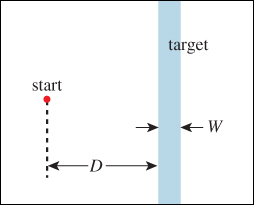
Figure 21.1: In the Fitts’ Law experiment, the user must move a pointer (real or virtual) from the red start point at left to the blue strip at right as fast as possible.
The b factor is an adjustment for units (the logarithm is unitless, but it needs to be converted to seconds) and for the base of the logarithm; the a term represents the minimum time for any task—it accounts for the time it takes to perceive and understand the task, to convert this understanding into a nerve activation, etc.
For most applications in interface design, the details of the law are unimportant. But a few general principles can be derived from the law.
• Large targets are easier to hit than small ones, especially when the “largeness” is in the direction of necessary motion.
• Closer targets are easier to hit than remote ones of the same size.
Furthermore, careful measurement shows that the constant b is device- and action-dependent: Moving a mouse pointer and moving a pen tip involve different constants; dragging with the mouse is slower than simply moving and then clicking.
As you think about a cursor-based interface design, with the cursor controlled by a pen, for instance, you should ask yourself, “What things am I most likely to do with the pen?” and “How can I make these things easy to accomplish?”
The answer to the first question is application-dependent, but the answer to the second is more generic. For instance, we can make the simple observation that among all locations on the screen, the one most rapidly reachable by the cursor is the cursor’s current location (see Figure 21.2). The next most reachable points are the four corners of the screen, because of the convention that the pen cursor never moves outside the screen: A motion to any point in the infinite quadrant associated to a corner requires no real precision in either the horizontal or vertical dimension. The four edge strips are similarly easy to reach, although they require some control in either the horizontal or vertical dimension.
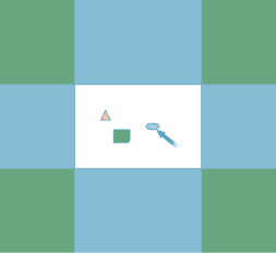
Figure 21.2: The quadrants (green) associated to corners are easy targets for cursor motion; the strips (blue) associated to screen edges are also good.
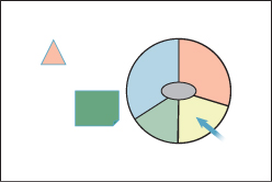
One consequence of the “point beneath the cursor is easy to reach” idea is that pie menus (menus that appear beneath the cursor, in which a drag into one of several sectors selects an option) are extremely easy to access (see Figure 21.3). Adjusting the sector sizes makes selecting common operations even easier, and muscle memory lets advanced users select from such menus without even looking at them.
A consequence of the “corners and edges of the screen are good targets” idea is that placing menus for all programs at the top of the screen may make interaction more efficient than locating them at the tops of individual windows. Of course, the initial interaction with a previously inactive program may be slower: The program must first be selected to activate it, and thus place its menu at the top of the screen. By contrast, in the “menus in windows” model, the program selection and menu selection may be combined into a single action.
By the way, generalizations of Fitts’ Law give us estimates of the difficulty of reaching two-dimensional targets [GKB07], and of steering through a narrow (possibly winding) channel to a goal [AZ97], a result that’s been discovered independently in several disciplines [Ras60, Dru71]. Fitts’ Law also seems to extend quite naturally to multitouch devices [FWSB07, MSY07]. These extensions, too, can be used to guide your designs.
21.2.2. Interaction Event Handling
You’ve written programs in which clicking a button on the interface, or selecting a menu item, caused something to happen. The 2D test-bed program described in Chapter 4 contains examples of such interaction. The method used there is overriding methods. There’s a Button class with a buttonPressed method that does nothing. We create a new class in which buttonPressed is overridden to do something useful for us. The system watches for events like a button press, and when they occur it invokes the appropriate method.
There are alternative approaches. In some object-oriented programming approaches, objects can respond to messages sent to them, rather than having methods that can be invoked. When a button is created in such a system, it’s told what message to send and where to send it, in response to a button press.
In some non-object-oriented systems, you pass a function pointer to a procedure that creates a button. When the button is pressed, the function is called.
These are all just minor variations on a single theme. At a lower level, the fact that the mouse button was pressed at all must be noticed and handled. There are basically two approaches. In one, the button press generates an interrupt, and an interrupt handler is invoked to determine the location of the cursor and then dispatch the event to the appropriate button, for instance. In another, the button press enqueues an event on an event queue, which an interaction loop is constantly polling—checking to see if there are new events to be processed. (The distinction is similar to that between preemptive and cooperative multitasking.)
Your choice of programming language, hardware, and operating system may influence which variety of system you end up using. But none of these substantially restrict general interface functionality: It’s usually possible to get the same results in all cases.
In all the examples that follow, we use click-and-drag functionality: Some location(s) is/are selected, the location point is moved, and as a result something else is changed. Finally, the selection is released. In the 3D manipulation examples, the location selection comes from a mouse click, the move comes from a mouse drag, and the mouse-button release terminates the selection. In the photo-manipulation example, the selection comes from a finger contact, the move comes from contact motion, and the release comes when the finger is lifted from the interaction surface. But in all cases, there are multiple states of the system:
• The pre-interaction state
• The “selected” state
• The “dragging” state
• And the post-interaction state
In practice, we reduce this to two states: noninteraction and dragging. The course of a typical interaction can be described by a finite-state automaton (FSA) with these two states and four arcs (see Figure 21.4).
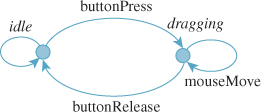
Figure 21.4: We are usually in the idle state. A click transitions to the dragging state; dragging remains there; a button release returns us to the idle state.
In general, FSAs provide a good structure for planning interaction sequences, which are seldom as simple as these. Unfortunately, as post-WIMP interactions evolve, the associated FSAs can become impossibly complex (imagine the FSA that might describe all possible interactions with your robotic butler in the future!), but for WIMP interactions, they can be a very useful tool.
21.3. Multitouch Interaction for 2D Manipulation
Multitouch interfaces are becoming increasingly common. We manipulate pictures on our smartphones using a thumb and index finger to translate and scale the pictures, for instance. Let’s consider the implementation of this 2D manipulator, represented schematically in Figure 21.5.
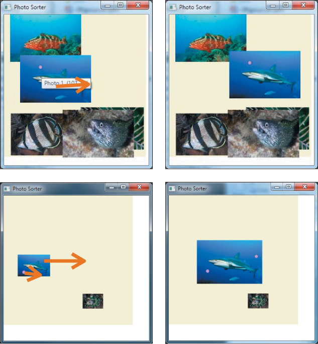
Figure 21.5: A photo-manipulation interface. (Top) A touch (shown by the pink dot in the shark photo) and drag (the large orange-brown arrow) moves a photo to a new location. (Bottom) Two contacts are spread apart to move and enlarge the photo. (©Thomas W. Doeppner, 2010.)
Notice three things about the interaction.
1. The position of the touch points in the image remains approximately constant. In the first case, the initial touch was a little above and to the left of center; after the move, it remains in the same place.
2. In the move-and-scale interaction, the fingers widen more horizontally than vertically, but we have to choose a single scale amount. One alternative is to resize the image to accommodate the larger change. Another alternative is to average the horizontal and vertical widening fractions (i.e., a vertical stretch of 20% and a horizontal stretch of 30% would result in a uniform scale of 25%). A third possibility, and the one we choose, is to scale by the ratio of contact distances: If the distance between the contacts doubles, we scale by a factor of two.
3. We’ve chosen to scale uniformly, even though nonuniform scaling of photos makes sense. That’s because nonuniform scaling is so much less common, and it’s so difficult to move your fingers in exactly proportional amounts, that it makes more sense to restrict to uniform scaling for convenience.
21.3.1. Defining the Problem
There are many possible ambiguous situations that still remain. What happens when the user starts by grabbing the upper-right and lower-left corners, and rotates these contacts to the upper left and lower right, respectively? According to rule 1 above, the picture should flip about its vertical axis to maintain contact-point correlation, but that’s a nonuniform scale, which contradicts rule 2. We in fact choose rule 3 rule as the dominant one, since opening and closing the fingers is much easier than rotating the hand, and so the inconsistency of contact points isn’t likely to be a problem in general.
By how much should we translate the photo during a two-finger interaction? We could translate the photo so that the first contact point remained underneath its finger, but the other perhaps did not. We could translate by the average of the two contact-point translations. We could translate so as to preserve the lower-left contact point, whether it’s the first or the second, on the grounds that for right-handed people, this is likely to be the thumb contact. We’ll choose the second, but there’s a good argument to be made for each of the others. The only way to decide conclusively is through user testing.
Now we have a complete problem definition: We’ll translate the photo so that the midpoint of the two contacts moves as specified, and we’ll scale it about that midpoint by the ratio of the contact distance after to the contact distance before.
The mathematical portion of the solution is now straightforward: We first scale the object about the initial midpoint, and then translate that midpoint to its new location.
21.3.2. Building the Program
To place our photo manipulator in context, we’ll assume that there are several photos in a scene, represented by a very simple scene graph: a “background,” representing an infinite canvas on which the photos are placed, with a global translate-and-scale transformation, and n photos, each with its own translate-and-scale transformation (see Figure 21.6). We “see” the parts of the photos that, after transformation, are visible in the unit square 0 ≤ x, y ≤ 1. When we manipulate a particular photo (or the background), we will alter its transformation and none of the others.
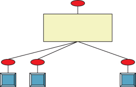
Figure 21.6: The background canvas (yellow rectangle) has its own scale-and-translate view transformation (the top red ellipse), and each photo (blue square) has a scale-and-translate as well.
We’ll assume that the manipulation is to be done in the form of callbacks, one for each contact event, where a contact is the touch of a digit to the interaction surface: We get informed when there’s a new contact, a contact drag, and a contact release. When two contacts move at once (as in the move-and-resize action), we’ll get a callback for each one (in no particular order). Each callback will identify the contact with which it’s associated. And at the start of the photo-manipulator application, the program will register with the operating system to receive callbacks for all such interactions.
When, for instance, a touch and drag begins, the application’s new-contact callback will be invoked; it handles this by creating an Interaction object to handle the remainder of the interaction sequence. That interaction object registers for subsequent callbacks, and after receiving each and processing it, marks it as having been handled so that no other registrants like the application itself get that callback. When the interaction is completed (by a contact-release event), the interactor can unregister itself, and subsequent callbacks will once again go to the application (see Figure 21.7).
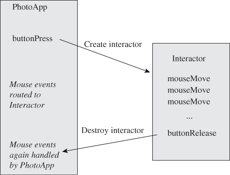
Figure 21.7: Callbacks to the application result in the creation of an interactor, which handles subsequent callbacks until done.
21.3.3. The Interactor
The interactor, at initialization, must do the following.
1. Identify which photo is being manipulated (and if the contact is not within a photo, record that the background is being manipulated).
2. Record the initial point of contact.
3. Record the initial transformation T0 for the photo or background.
4. Keep a reference to the transformation for the selected photo (or background) in the scene graph. (Because we do the same thing whether a photo or the background is selected, we’ll refer to the selected photo from now on.)
Let’s imagine, for the time being, that the interaction is a simple single-finger click and drag, with no scaling involved. Then our strategy for implementing the interaction during dragging is as follows.
1. At each drag, compute the offset d between the current contact and the initial contact.
2. Let T be the transformation which is translation-by-d.
3. Replace the transformation for the selected photo with T ![]() T0 (i.e., first do whatever transformations were done previously, and then translate by T).
T0 (i.e., first do whatever transformations were done previously, and then translate by T).
Notice that rather than accumulate incremental motions, we use the offset from the original point. Accumulating increments can also work, but numerical problems may make the sum of the increments different from the total motion for long drag sequences, making the photo appear to “slip” around the contact point that’s being dragged. We discuss this further in the case of virtual sphere rotation.
Note that in either case—accumulated incremental motions, or a single translation determined from the start point and current point—the translation is composed with the existing transformations on the photo, and thus should be described as a “relative” transformation rather than an absolute one.
At the end of the interaction, when the contact is broken, we need only destroy the interactor.
The code outline, in an informal approximation of C#, is shown in Listing 21.1.
Listing 21.1: Outline of interaction code for photo manipulation application.
1 Application:
2 main()
3 build scene graph for photos and display the scene register newContact, dragContact,
4 releaseContact callbacks
5
6 public newContactCallback(Scene s, Contact c)
7 Interaction ii = new Interactor(c)
8
9 Interactor:
10 private Contact c1
11 private Transform2 initialXform
12 private Point2 startPoint
13 private FrameworkElement controlled
14 private PhotoDisplay photoDisplay
15
16 public Interactor(Contact c)
17 c1 = c
18 intialPoint = c1.getPoint()
19 controlled = the photo (or background) that’s at initialPoint
20 initialXform = controlled.getTransform()
21
22 register for all contact callbacks
23
24 public dragContactCallback(Contact c)
25 if c1 != c {signal an error}
26 Vector2 diff = c.getPoint() - initialPoint
27 Transform2 T = new Translation(diff)
28 s.setTransform(o, initialXform*T)
29 redisplay scene
30
31 public releaseContactCallback(Contact c)
32 if c1 != c {signal an error}
33 unregister this interactor for callbacks
We’re assuming here that we have point, vector, and transformation classes, and that composition of transformations is represented by the overloaded * operator, in which S * T is the transformation that applies S and then T. Furthermore, we assume that each object (photo or background) stores its own transformation, rather than the transformations being stored in a scene-graph object.
All of these assumptions hold in WPF, and a WPF implementation of this photo manipulator is available on this book’s website. Rather than using actual multitouch contacts, which may not be available to all readers, the program simulates them by letting the user right-click to create or destroy a “contact” (shown as a small marker) and then left-click and drag to move contacts.
WPF also provides pick correlation—a report of which object in a scene is visible at the pixel where the user clicks, as needed at line 19 in Listing 21.1.
What changes must be made to allow for two-contact interaction? When the second contact happens, we’ll treat the first contact’s click-and-drag sequence as having terminated (i.e., we’ll start from the current photo’s current transformation, and forget that we ever had an initial transformation or contact point).
For a two-contact interaction, we’ll (a) treat the midpoint of the two contacts as pinned to the photo so that when the midpoint moves, the photo moves, and (b) scale the photo relative to the distance between the fingers so that if the fingers move together the photo is unscaled, and if they widen the photo enlarges, etc. We’ll record the midpoint and vector difference of the contacts at the start, and at each update we’ll build an appropriate scale-and-translate transformation. In other words, we’ll do just what we did for the single-contact click and drag, but now we’ll do it by remembering the initial positions of two contact points, and we will include scaling.
Because the interaction sequence might look like “touch with one finger, drag to the right, touch with the thumb as well, drag farther to the right and widen the distance of the finger to the thumb,” we must also track the number of contact points. Whenever this number changes, we’ll restart our tracking. Listing 21.2 shows the differences, except for what happens when a contact moves.
Listing 21.2: Handling the varying number of contact points.
1 Interactor:
2 private Contact c1, c2;
3 private Transform2 initialXform
4 private Point2 startPoint
5 private FrameworkElement controlled
6 private PhotoDisplay photoDisplay
7 private Vector2 startVector
8
9 public Interactor(Scene s, Contact c)
10 c1 = c; c2 = null;
11 startPoint = c1.getPoint()
12 initializeInteraction()
13 ...
14
15 // if there’s only one contact so far, add a second.
16 public void addContact(Contact c)
17 if (c2 == null)
18 c2 = newContact(e);
19 initializeInteraction();
20
21 private void initializeInteraction()
22 initialFform = controlled.GetTransform();
23 if (c2 == null)
24 startPoint = c1.getPosition();
25 else
26 startPoint = midpoint of two contacts
27 startVector = c2.getPosition() - c1.getPosition();
28
29
30 public removeContact(Contact c)
31 if only one contact, remove this interactor
32 otherwise remove one contact and reinitialize interaction
When a contact point moves, we have to adjust the transformation for the relevant photo. Listing 21.3 gives the details.
Listing 21.3: Handling motion of contact points.
1 public void contactMoved(Contact c, Point p)
2 if (c2 == null)
3 Vector v = p - startPoint;
4 TransformGroup tg = new TransformGroup();
5 tg.Children.Add(initialTransform);
6 tg.Children.Add(new TranslateTransform(v.X, v.Y));
7 controlled.SetTransform(tg);
8 else
9 // two-point motion.
10 // scale is ratio between current diff-vec and old diff-vec.
11 // perform scale around starting mid-point.
12 // translation = diff between current midpoint and old
13 Point pp = getMidpoint(); // in world coords.
14 Point qq = startPoint;
15 pp = photoDisplay.TranslatePoint(pp, (UIElement) controlled.Parent);
16 qq = photoDisplay.TranslatePoint(qq, (UIElement) controlled.Parent);
17 Vector motion = pp - qq;
18
19 Vector contactDiff = c2.getPosition() - c1.getPosition();
20 double scaleFactor = contactDiff.Length / startVector.Length;
21 TransformGroup tg = new TransformGroup();
22 tg.Children.Add(initialTransform);
23 tg.Children.Add(new ScaleTransform(scaleFactor, scaleFactor, qq.X,qq.Y));
24 tg.Children.Add(new TranslateTransform(motion.X, motion.Y));
25
26 controlled.SetTransform(tg);
This code uses several WPF conventions that deserve explanation. First, a TransformGroup is a sequence of transformations that are applied in order; thus, in the if clause, we first perform the initial transformation to the photo, and then translate it. Second, the line
pp = photoDisplay.TranslatePoint(pp, (UIElement) controlled.Parent)
transforms the point pp from the world coordinate system (that of the PhotoDisplay) to the coordinate system of the parent of the current photo (the background canvas). In the case where the background canvas is being manipulated, it transforms the point to the coordinate system of background’s parent, that is, the PhotoDisplay. Thus, the computed translation qq - pp is the one to apply after the photo has been scaled, but before it is further transformed by the transformation associated to the background. It’s essential that the point pp start in world coordinates for this to work properly. If it were, say, in the coordinate system of the photo, we’d have to transform it to the photo’s parent.
21.4. Mouse-Based Object Manipulation in 3D
The same general approach—build an interactor that handles a click-and-drag sequence by editing the transformation on a target object—works in 3D as well. A closely related idea is that the relationship of object to view is symmetric: In a view of a scene with only a single object, we can move the object to the right, or the camera to the left, and get the same change in the eventual image. Thus, a slightly modified version of the interaction we use for object manipulation can be used for camera manipulation.
21.4.1. The Trackball Interface
In the trackball model, we imagine that an object is suspended in a transparent solid ball with center C that can be rotated by the user; a click and drag on the ball’s surface, from a starting point A to an endpoint B, defines a rotation: The ball is rotated in the plane of A, B, and C, with C as the center of rotation, so as to move A to B. (This is also called the virtual sphere model.)
Under what conditions on A, B, and C is the rotation ill-defined? Can you think of a situation in a typical interaction where this might be a problem, or will such a problem never arise?
![]() We’ve specified the rotation quite carefully. If A and B are two distinct but nonantipodal points of a sphere, describe the set S of rotations of the sphere that take A to B. Is S a finite set? The space SO(3) of sphere rotations is three-dimensional. Is S a zero-, one-, two-, or three-dimensional subset of it?
We’ve specified the rotation quite carefully. If A and B are two distinct but nonantipodal points of a sphere, describe the set S of rotations of the sphere that take A to B. Is S a finite set? The space SO(3) of sphere rotations is three-dimensional. Is S a zero-, one-, two-, or three-dimensional subset of it?
In this interaction sequence, a right-click on the object (our demonstration example has only a single object) makes a transparent sphere appear surrounding the object; a first left-click on the sphere initializes a rotation action; and a drag to a new point defines a rotation, which is applied to the object so that it appears to be dragged within the transparent sphere. The mouse release makes the currently applied rotation permanent. By the way, undragging (i.e., returning to the starting click point) resets the transformation to its initial value.
In the implementation, we need to do three things.
1. Create the transparent sphere and respond to click, drag, and release events there.
2. Handle a click event by recording the current transformation on the object, and storing the initially clicked point. It’s best to store this in the frame of reference of the object at the time of clicking.
3. Handle drag events by transforming the current mouse position into the frame of the object at initial-click time, and then computing the rotation that takes the initial click to the current mouse position. This rotation is applied to the object, followed by its pre-drag transformation.
There is one tricky problem: What happens when the drag leaves the sphere? For this, we project back onto the sphere: We find the sphere point closest to the eye-through-cursor ray, and pretend that the cursor is there.
With this in mind, let’s look at the code. We start by creating a scene (see Figure 21.8) containing a single manipulable object, a cube. If pick correlation shows a right-click on the cube, we create an interactor to handle the subsequent interactions:
1 public partial class Window1 : Window
2 private RotateTransform3D m_cubeRotation = new RotateTransform3D();
3 private ModelVisual3D m_cube1;
4 private Interactor interactor = null;
5 public Window1()
6 // initialize, and build a ground and two walls
7 m_cube1 = a cube model
8 m_cube1.Transform = new TranslateTransform3D(4, .5, 1);
9 mainViewport.Children.Add(m_cube1);
10
11 this.MouseRightButtonDown +=
12 new MouseButtonEventHandler(Window1_MouseRightButtonDown);
13 add handlers that forward left-button events to the interactor, if it’s not null.
14
15 void Window1_MouseRightButtonDown(object sender, MouseEvent e)
16 // Check to see if the user clicked on cube1.
17 // If so, create a sphere around it.
18 ModelVisual3D hit = GetHitTestResult(e.GetPosition(mainViewport));
19 if (hit == m_cube1)
20 if (interactor == null)
21 interactor = new Interactor(m_cube1, mainViewport, this);
22 else
23 endInteraction();
24 // if there’s already an interactor, delegate to it.
25 else if (interactor != null)
26 interactor.Cleanup();
27 interactor = null;
The interactor, just as in the photo-manipulation example, keeps track of the manipulated object (controlled) and the transformation for that object at the start of the manipulation. We also note the viewport from which the object is seen (which allows us to transform mouse clicks into rays from the eye). Initializing the interaction consists of recording the initial transformation on the controlled object, and creating a transparent sphere, centered at the object center. The corresponding cleanup procedure removes the sphere.
1 private void initializeInteraction()
2 initialTransform = controlled.Transform;
3 find bounds for selected object,
4 locate center and place a sphere there
5 viewport3D.Children.Add(sphere);
6
7 public void Cleanup()
8 viewport3D.Children.Remove(sphere);
9 initialTransform = null;
When the user left-clicks on the sphere, we record the current transformation associated to the controlled object and the location of the click. Just as in the photo-manipulation program, we record this position in the coordinate system of the parent of the controlled object. We also record that we are in the midst of a drag operation, and when the left button is released, we reset the drag status.
1 public void mouseLeftButtonDown(System.Windows.Input.MouseButtonEventArgs e)
2 ModelVisual3D hit = GetHitTestResult(e.GetPosition(viewport3D));
3 if (hit != sphere)
4 return
5 else if (!inDrag)
6 startPoint = spherePointFromMousePosition(e.GetPosition(viewport3D));
7 initialTransform = controlled.Transform;
8 inDrag = true;
9
10 public void mouseLeftButtonUp(System.Windows.Input.MouseButtonEventArgs e)
11 inDrag = false;
12
13 private Point3D spherePointFromMousePosition(Point mousePoint)
14 form a ray from the eye through the mousePoint
15 if it hits the sphere
16 return the hit point.
17 else // ray misses sphere
18 return closest point to ray on the sphere
Finally, just as before, the meat of the work is done when the mouse moves: We find the new location of the mouse (in the coordinate system of the controlled object’s parent), build a rotation in that coordinate system, and append this rotation to the controlled object’s initial transformation.
1 public void mouseMove(System.Windows.Input.MouseEventArgs e)
2 if (inDrag)
3 Point3D currPoint = spherePointFromMousePosition(e.GetPosition(viewport3D));
4 Point3D origin = new Point3D(0, 0, 0);
5 GeneralTransform3D tt = initialTransform.Inverse;
6 Vector3D vec1 = tt.Transform(startPoint) - tt.Transform(origin);
7 Vector3D vec2 = tt.Transform(currPoint) - tt.Transform(origin);
8 vec1.Normalize();
9 vec2.Normalize();
10 double angle = Math.Acos(Vector3D.DotProduct(vec1, vec2));
11 Vector3D axis = Vector3D.CrossProduct(vec1, vec2);
12 RotateTransform3D rotateTransform = new RotateTransform3D();
13 rotateTransform.Rotation = new AxisAngleRotation3D(axis, 180 * angle/Math.PI);
14
15 Transform3DGroup tg = new Transform3DGroup();
16 tg.Children.Add(rotateTransform);
17 tg.Children.Add(initialTransform);
18 controlled.Transform = tg;
Before leaving the trackball interface, let’s examine some of the design choices and variants. First, initiating a rotation requires clicking on the object. That in turn requires moving the pointer so that it appears over the object. Fitts’ Law tells us that this may be a somewhat costly operation if the object is far from the current pointer location. On the other hand, shifting our attention to the object happens at the same time, so we can perhaps regard some of the cost as amortized. Having selected the object with the first click, we then rotate it with a drag, which is ideal from a Fitts’ Law perspective: The drag starts at the most easily accessible location, the current pointer position. How large a drag is required? That depends on the radius of the virtual sphere: A rotation of 90° will require a cursor motion equivalent to the sphere’s projected radius. This suggests that a small radius is ideal. On the other hand, precisely placing the cursor within that small radius can be difficult; a larger sphere gives the user more precise control of the rotation. Depending on which is more important for the context, speed or precision, the designer should adjust the standard interaction-sphere size.
On the mathematical level, we’ve chosen to work with an integral form of the interface: The initial point is clicked, and the rotation of that point to the current point is recomputed for each bit of dragging. As an alternative, we could have used a differential version, in which the motion from the previous cursor point to the current one is used to generate a tiny rotation, and these tiny rotations are accumulated by multiplying them into the transform of the object. Unless the cursor moves along a great circle arc during the drag, the differential and integral forms give different results. In the differential version, making small circles about the initial click point generates a spin about that point; making circles in the opposite direction generates the opposite spin. Users sometimes find this useful. On the other hand, in the integral form, a drag that ends at the initial point always brings the object back to its starting orientation, which users may also find useful.
In the differential form, we “accumulate” many small rotations by multiplying them together in the form R1R2R3 ... Rk, where k can be quite large. While each Ri may be a rotation matrix within the bounds of numerical precision, their product may end up differing from a rotation by a large amount because of roundoff errors; the result can (and should!) surprise the user. A solution to this is to accumulate the rotations and then, after perhaps ten are accumulated, reorthogonalize the matrix with the Gram-Schmidt process.
Even with this reprojection onto the set of rotation matrices, the differential form has another drawback. The exact same cursor click-and-drag sequence, executed on two identical scenes, may produce different results. That’s because the mouse motion is sampled by the operating system, and depending on other loads on the machine, the samples may not occur at exactly the same moments. Thus, the two sequences of points used to produce the two sequences of rotations may differ slightly, and the final results will generally differ as well. This is not usually a problem unless the load is rather high so that sampling occurs at a rate that fails to accurately represent the cursor path. For example, if the cursor is moved in a small circle over the course of a half-second, but only two position samples are taken during that time, the results will be very different than if ten samples are taken.
![]() In general, it’s a bad idea to try to numerically integrate differentials, or even very small differences, for the reasons given above. There are two exceptions. First, such an integral may be the only practical way to compute a value. In studying light transport, for example, computing the light arriving at the eye amounts to evaluating an integral, one for which the only known methods are numerical (see Chapter 31). The second is where the summed quantity is known to be an integer; in this case, roundoff errors, if they’re known to be small, can be removed by rounding. (For instance, if you sum four terms and get 3.000013, you can safely assume that the value is 3.)
In general, it’s a bad idea to try to numerically integrate differentials, or even very small differences, for the reasons given above. There are two exceptions. First, such an integral may be the only practical way to compute a value. In studying light transport, for example, computing the light arriving at the eye amounts to evaluating an integral, one for which the only known methods are numerical (see Chapter 31). The second is where the summed quantity is known to be an integer; in this case, roundoff errors, if they’re known to be small, can be removed by rounding. (For instance, if you sum four terms and get 3.000013, you can safely assume that the value is 3.)
21.4.2. The Arcball Interface
The arcball interface [Sho92] is exactly like that of the trackball, except that the sphere rotates twice as far as the drag would suggest. That is to say, if you drag from A to B, and they’re 30° apart on the sphere centered at C, the object will rotate 60° in the plane of A, B, and C.
This has several practical implications. First, even though we can only see and click on the front half of the sphere, we can perform every possible rotation: Dragging the nearest point to the contour rotates it all the way to the farthest point, for instance. Second, dragging from P to Q, then Q to R, then R to P (where all three are points on the sphere) results in no rotation at all.
In evaluating the arcball, much of what we said about the virtual sphere still holds. If the interaction sphere is textured with some recognizable pattern, such as a world map, then there is some surprise for the user who clicks and drags London: During the drag, London slides out from under the cursor. With a transparent sphere, this effect is largely invisible, however, and the interaction feels quite natural. (If we were to implement a translation-by-dragging interface and translated by twice the drag vector, it would almost certainly be disconcerting to the user, however.)
21.5. Mouse-Based Camera Manipulation: Unicam
We now move on to the topic of manipulating the view of a scene. It’s easy to imagine that this is just the same as manipulating an object; after all, the camera transformation is part of the scene graph in exactly the same way that the transformations on objects are. In more basic terms, if we want to see the left-hand side of a box, we can either rotate the box to the right or move our eyes to the left. It’s not very difficult to adapt the trackball or arcball interface to act on the scene as a whole rather than on a particular object, and thus achieve this effect. For a square viewport, we simply draw a manipulator sphere that touches all four sides of the viewpoint, thus giving maximal precision in control of the camera. Unfortunately, when we do so we find it’s not very satisfactory: The camera keeps tilting away from “upright,” and while being able to make a single object tilt is convenient, having a tilted camera is so rarely what’s wanted that it’s a constant annoyance. This is a situation where context (the traditional human experience of having the vertical almost always be “up” in our view of the world) should influence design.
Furthermore, camera control involves more than just the orientation of the camera: You may wish to look somewhere else (at some other object), or get closer to the object you’re looking at. For the first of these (panning), there’s a fairly natural interaction: You can click on the object you want to look at and drag it to the center of the screen. If it’s off-screen, multiple panning steps may be needed. Of course, you need to do something to indicate that you’re panning rather than rotating; that is, you need a notion of “mode.” For the second (dollying), there’s no obvious interaction, even once you’ve established you’re in dollying mode.
Unicam [ZF99] is a camera-manipulation mechanism that allows for controlling the three rotational degrees of freedom and the three translational degrees of freedom in a virtual camera with a single integrated system. Other features common to virtual cameras (clipping, plane distances, view angle, and film-plane rotations for view-camera effects) are so rarely adjusted that they are not included, just as we omitted image rotation in our photo-manipulation application. The implementation is so very similar to that of the other manipulators we’ve described that we’ll simply describe how the interface feels to the user. Unicam can actually be used for both perspective and orthographic cameras, but we’ll only describe the more common perspective camera case here.
Because Unicam is designed for applications in which camera control is a frequent operation (e.g., solid modeling), a single mouse button is entirely allocated to it: All camera operations are performed by click and drag with this one mouse button. This reduces the transition time and effort when the user wants to switch between camera operations and other application operations controlled by other mouse buttons.
With Unicam, the viewing window is divided into two regions (see Figure 21.9): an inner rectangle in which interactions determine camera translations and a border where they determine rotations.
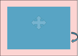
Figure 21.9: In the blue inner rectangle, mouse motions induce camera translations. In the pink border region, mouse motions determine rotations.
Unicam maintains a notion of a hit point, a place that represents the location of the user’s focus of attention. Typically, this is the scene point under the cursor (i.e., the first point hit by tracing a ray from the eye through the cursor point on the film plane into the scene). In the event that this ray hits nothing in the scene, the hit point is the projection of the previous hit point onto this ray.
21.5.1. Translation
A click and drag in the translation area is initially classified as “horizontal” or “vertical” by examining the first few pixels of motion. (The authors suggest about 1% of the screen width as a reasonable distance to use in determining primary direction, and say that this categorization must be done in the first 0.1 sec to avoid disturbing the user.) An initially horizontal motion introduces a camera translation in a direction parallel to the film plane in such a way that the hit point remains beneath the cursor. Thus, a click and drag to the right causes the camera to move to the left in the scene so that the hit point moves the appropriate distance to the right in the resultant image.
An initially vertical cursor motion indicates a different mode of interaction. Left-right motion continues to act as before, performing film-plane-parallel motion to the left or right, but vertical motion translates the camera along the ray from the camera to the hit point. The authors make an interesting choice for how cursor motion is converted to translation toward the object: The conversion is linear, with a motion from the bottom to the top of the interaction window corresponding to the distance from the camera to the hit point. This makes it impossible to “overshoot” the hit point, but makes it easy to approach the hit point with a kind of logarithmic interaction: Multiple half-screen vertical cursor motions each divide the distance to the hit point by two.
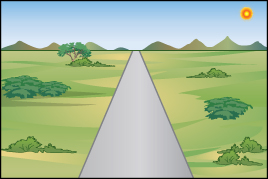
The assignment of vertical cursor motion to dollying is an apparently arbitrary choice; the authors could have chosen to use horizontal motion. But they report that users find the vertical motion far more natural, perhaps because we are familiar with scenes like that shown in Figure 21.10, in which the horizontal layout of the terrain makes the correspondence between vertical position and distance obvious. (Try to think of a situation in which there’s a similarly strong relationship between horizontal position and distance; is it a commonplace or familiar situation?)
21.5.2. Rotation
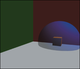
While there are three rotational degrees of freedom, such rotations must have a center of rotation. (A rotation about one center can be converted, by a translation, into a rotation about any other center, but we need a particular center to start from.) The camera location itself is one possible center of rotation, and it corresponds well to our physical structure, in which you can bend your neck to look up or down, and can rotate it to look left and right. But when your attention is focused on some object, “orbiting” around the object feels more natural than turning your head and then stepping to the side to bring the object back into view. In Unicam, a click and release on a scene object places a small blue sphere (the focus dot) at the hit point, and subsequent rotations are all interpreted as rotations about this focus dot.
Alternatively, the user can click in the border area to invoke rotation about the view center, a point on the ray from the camera through the center of the view. The distance along that view ray is determined by the current hit point: The perpendicular projection of the hit point onto the view ray is the view center.
In the case of a focus dot, a subsequent click and drag anywhere on the view begins a rotation; in the case of a view-centered rotation, the initial click in the border area initiates the rotation, and subsequent drags determine the amount of rotation. In each case, rather than using virtual-sphere or arcball rotations, the x- and y-coordinates of this mouse displacement from its initial click determine, respectively, rotation about the world “up” vector (usually y) and about the camera’s “right” vector (i.e., the vector pointing to the right in the film plane). Full-screen-width horizontal motion corresponds to 360° rotation about the up vector; full-screen-height motion corresponds to 180° rotation about the right vector, although this rotation is clamped to prevent ever arriving at a straight-up or straight-down view. The rotations are implemented sequentially: first a rotation about the up vector, then about the right vector.
21.5.3. Additional Operations
The focus dot also serves as a focus for further interactions: Clicking and releasing on the focus dot moves the camera to an oblique view of the underlying object, seen from slightly above the object. A click and drag up and to the right saves the current view into a draggable icon that can later be clicked to restore the view. Dragging down and to the right temporarily scales the focus sphere by enlarging its radius to the drag distance; upon release, the camera dollies inward until this enlarged sphere fills the view, at which point the focus sphere returns to its normal size. This allows the user to easily specify a region of interest. A drag in any other direction aborts the gesture.
21.5.4. Evaluation
Unicam presents the user with very easy access to the most common camera operations. By having many of the gestures start at the current cursor location, it takes greatest advantage of Fitts’ Law. By associating actions with a direct-manipulation “feel” (translation by dragging feels as if you are dragging the world with the cursor, and dollying by vertical motion feels like you’re moving along a train track toward its vanishing point), the designers make the operations easy to use and remember.
On the other hand, there are no affordances in the system. There’s nothing that tells you that the view’s border area can be used for rotation, or that its center can be used for translation. For an often-used feature like camera control, this is probably appropriate. Through constant use, the user will rapidly memorize its features. For controls that are used less often, some visual representation would be appropriate.
21.6. Choosing the Best Interface
We’ve seen two object-rotation interfaces and a camera-control interface. Many games provide camera controls that simply let you look left or right (by fixed increments) or up and down (by fixed increments), often controlled by keyboard keys. Architecture walkthrough programs let the user move through a building, by typically constraining the eye height to something near 1.8 m, and prevent motion that passes through walls, etc. Which interface is best? The answer is that among well-designed interfaces (e.g., ones that pay attention to matters of affordance and Fitts’ Law), the best choice almost always depends on context. In an architecture walkthrough application, the camera-control interface should restrict the eye height and prevent passing through walls; in a CAD/CAM system for designing an aircraft, being able to view places that are inaccessible to humans (e.g., the cable-routing channels in the airframe) is essential, and eye height and collision-prevention elements in an interface would be annoying.
21.7. Some Interface Examples
In this section, we briefly describe some of our favorite interaction work. The results range from items you’ll want in your toolbox of ideas to ones that are single-application interfaces where the interface is enabled by new underlying graphics technology. Other good ideas, like pie menus, tool trays, and Unicam, have already been described elsewhere in this chapter, and there are so many good ideas that we cannot possibly be exhaustive here. This is an idiosyncratic list of ideas we’ve found important, useful, or inspiring.
21.7.1. First-Person-Shooter Controls
These FPS controls provide keyboard control of view and camera motion in many video games. They make a nice addition to any other camera control mechanism you have in your program: They’re easy to learn and widely applicable. In one form, they use the arrow keys: The up and down keys move the viewer forward and backward; the left and right keys typically “strafe” to the left and right, although they can also be used to turn the view to the left or right. If you want to have nearby keys perform related functions (Fitts’ Law applies to the keyboard as well as the mouse), the arrow keys are less convenient. Instead, it’s typical to use W and S for forward and backward motion, Q and E to rotate the view to the left or right, and A and S for strafing (which, in nonshooting games, can be remapped to “peeking” to the left or right—the view is shifted somewhat to the left or right for the duration of the keypress, and it returns to a forward view when the key is released).
21.7.2. 3ds Max Transformation Widget
The ViewCube [KMF+08] is a 3D view manipulation widget (see Figure 21.11). It was developed by Autodesk and has been deployed in all of its 3D modeling products, which include AutoCAD, 3ds Max, Maya, and Mudbox. This makes it one of the most significant 3D user-interface elements in use today. The ViewCube was designed to address a long-standing problem in 3D modeling that has only grown as the popularity and importance of CAD and digital content creation have brought more designers in from 2D tools: user disorientation. The often-ambiguous third-person view of an untextured and often unfinished scene can easily leave the user without a sense of orientation or broader context for content creation applications. This is less problematic in applications like games, where a polished surrounding environment and strong lighting cues provide intuitive orientation cues.
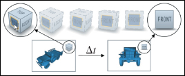
Figure 21.11: The basic modeling widget from 3ds Max (Courtesy of Azam Khan, ©2008 ACM, Inc. Reprinted by permission.)
The ViewCube always sits in the upper-right corner of the screen. It both provides intuitive orientation feedback and acts as a camera control widget. The orientation feedback is in the form of a subtle drop shadow indicating vertical orientation and explicitly labeled faces. The researchers who developed the ViewCube experimented with several alternatives to the text labels, such as embedding a small 3D view of the current object within the cube, but they found that the text was most effective. The 8 corners, 12 edges, and 6 faces of the cube each correspond to specific views. A user can click on zones near any of those with a mouse to warp to the predefined viewpoints relative to the center of the cube, or click and drag to rotate the cube to an arbitrary orientation (in the style of the arcball [Sho92]). The outlines of the cube are stroked as solid paths when the cube is at one of the 26 canonical views and dashed for intermediate views. In addition, small arrows (not shown in Figure 21.11) point to the four peripheral faces (which may not be visible) and support 90° roll rotations in the plane of the current view.
21.7.3. Photoshop’s Free-Transform Mode
When you are in free-transform mode in Photoshop and you select an image, its bounding box is shown with small square “handles” at the corners and edges. As the cursor moves over these handles, it changes to a double-headed arrow, disclosing that you can click and drag the handles. Corner drags reshape the bounding box (and its content) in both x and y; a shift-key modifier makes the changes in width and height be proportional. A control-key modifier lets the corner (or edge) be moved to any position, so the image is no longer rectangular. Edge drags move the selected edge; a shift modifier makes the opposite edge adjust as well so that a shift edge drag on the top scales the image around its horizontal centerline; a control-shift modifier lets the user shear the image (i.e., move the edge center along the line containing the edge).
When the cursor is slightly outside the bounding box, it becomes a curved double-headed arrow, indicating that you can rotate the box and its contents (see Figure 21.12). Finally, if you click on a corner and press appropriate modifier keys, you can apply a perspective transform to “keystone” the bounding box in either the horizontal or vertical direction, giving the appearance of perspective (see Figure 21.13).
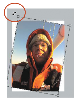
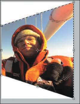
Figure 21.13: The image has been keystoned by dragging a corner along the left side; the bounding box remains unchanged, however.
21.7.4. Chateau
Chateau [IH01] is a system for rapidly creating highly symmetric forms. User input is processed to search for symmetries. For instance, if the user recently created a cylinder of length 5 and radius 1, and begins the gestures to create a new cylinder, indicating a length of approximately 5, the system offers up a completed cylinder in a thumbnail view, which the user can click to confirm that it’s what’s wanted. If there are multiple possible completions, the most likely (according to some heuristics) are offered. Once the second cylinder is placed somewhere, the system may propose a third cylinder, offset from the second in the same way the second is offset from the first, thus making it easy to create a row of columns, for instance.
While the particulars of this program are not especially relevant, the notion of a suggestive interface, in which candidate completions of actions are offered, leverages the “recognition is faster than recall” idea: The user can recognize the correct completion rapidly. Similar ideas are used in keyboard input for Asian character sets, where each character is represented by a quadruple of ASCII characters, but once the user types one or two ASCII characters, several “likely” choices are offered as completions, with likelihood being determined by things like recent use in the document, or even surrounding vocabulary or sentence structure.
The auto-completion used in text-messaging systems on mobile devices is similar, offering multiple completions. In the T9 input system, using the conventional “2 = ABC, 3 = DEF, 4 = GHI ...” mapping, a user types “432” and the system recognizes that the most likely word containing one of GHI, followed by one of DEF, followed by one of ABC, is “head” and offers it as a completion. The user can continue to type numbers (“54”) to select a longer word like “healing.” And in a radically different approach to text entry, the Dasher system [WBM00] (see Figure 21.14) displays text in boxes that approach a user-controlled point. When the point is moved to the right, the boxes move to the left, at a speed proportional to the displacement. As the point is moved up or down, the user can arrange for the point to pass through a particular box. Doing so produces the “keystrokes” shown in the box (typically a single letter). Using the statistics of the input language, the system places likely boxes near the middle, and unlikely ones at the top and bottom. In some cases, sequences of two or more characters may be very likely, and boxes containing those sequences end up “in line” so that it’s easy to pass through all of them. (For instance, if the user starts by selecting a “T,” the easiest two boxes to draw through are “h” followed by “e.”) By training the system (thereby altering its notion of likelihood) or introducing a custom vocabulary, a user can make it even more effective. This is a suggestive interface that can reasonably be used by the severely disabled.
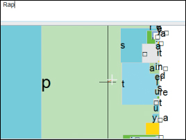
Figure 21.14: The user has chosen the characters R-a-p, shown in the upper left. The user will move the cursor upward so that the box labeled “t” passes over it, completing the word “Rapt.”
21.7.5. Teddy
Teddy [IMT99] is a system for the informal creation of smooth or mostly smooth 3D shapes. The user makes gestures that are interpreted as 3D modeling commands. For instance, at the start, if the user draws a simple closed curve, it is interpreted as the silhouette of a smooth shape; an “inflation” algorithm converts the silhouette into 3D. A stroke drawn across a shape cuts off part of the shape, as if it had been sliced with a sword. If the user draws a closed curve on the surface, then rotates the object so that this is near the silhouette, and draws a curve starting and ending on the first one, the system creates an “extrusion” from the base shape using the first curve as the cross section, and the second to determine the shape of the extrusion. This allows the rapid creation of interesting shapes (see Figure 21.15).
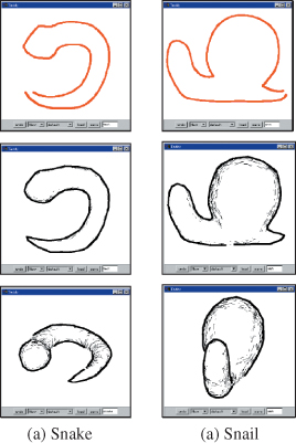
Figure 21.15: Examples of inflation of a 2D stroke by Teddy (Courtesy of Takeo Igarashi, ©1999 ACM, Inc. Reprinted by permission.)
The system is made possible by various mesh-construction and editing operations, but it is more notable for the coherence and simplicity of its interface design. By providing just a few simple operations, and making intuitive gestures to represent them, Teddy hits a sweet spot in shape creation. Not long after it was introduced, it was used as an avatar-creation interface in a video game, with thousands of users.
21.7.6. Grabcut and Selection by Strokes
Another example of a technology-enabled interface is Grabcut [RKB04], a system for automatically dividing an image into foreground and background portions, given a user’s input—a closed curve that mostly surrounds foreground and not too much background. The system then creates a statistical model of each set (foreground and background) of pixels, based on the kinds of colors that appear in each one. From this model, one can ask, for a given pixel color, “How likely is it that this pixel was drawn from the foreground distribution? From the background distribution?” Doing this for every pixel in the image, one can find large areas that are “likely to be background” and large areas that are “likely to be foreground,” and some pixels that are ambiguous. The system then tries to find a partition of the image into foreground and background regions with two goals.
1. Pixels that are more likely to be foreground than background are generally labeled as foreground, and similarly for background.
2. Adjacent pixels tend to have the same labels.
These goals allow the system to assign a score to a partition, which in turn means that finding the best partition is an optimization problem. The optimization can be framed as an instance of the min-cut problem, for which approximation algorithms have recently been developed [BJ01]. The system finds an optimal partition, rebuilds the foreground and background models based on the new partition, and repeats the operation until the result stabilizes. (The algorithm also handles subpixel partitioning through local estimates of mixtures of foreground and background, but those details are not important here.)
The end result is that the user need only express rather general intent (“separate stuff like this from stuff like that”) to accomplish a rather difficult task. (Actually drawing outlines around foreground elements in programs like Photoshop with more basic tools, or even “smart scissoring” tools, is remarkably time-consuming.)
The Grabcut approach has been improved upon with a “scribbling” interface, in which the user scribbles over some typical background regions, then changes modes and scribbles over some typical foreground regions. The scribbled-on pixels are used to create the foreground and background statistical models. In situations where making a close outline of the foreground may be difficult (e.g., a gray octopus on a coral bed), it may still be easy to mark a large group of representative pixels (e.g., by scribbling on the octopus body rather than its arms).
Grabcut has its own advantages, however: If the foreground object is one person in a crowd, the enclosing curve in Grabcut can help prevent other people with similar skin tones from being included in the foreground, as they might be with the scribbling interface.
21.8. Discussion and Further Reading
While the techniques we’ve discussed in this chapter provide nice illustrations of the use of linear algebra and geometry in the manipulation of objects and views, they are merely a starting point. There are other camera-manipulation approaches (such as allowing the user to control pitch, yaw, and roll about the camera itself), which, while easy to understand, can easily lead to disorientation; in a sparsely populated world—a geometric modeling system in which you’re crafting one object, for instance—it’s easy to rotate the camera to “look at nothing,” and then have trouble refinding the object of interest. Similarly, it can be easy to zoom or dolly so far out that the object of interest is subpixel in size, or so far in that the entire view is covered by a single tiny part of the object, rather like standing with your nose against the outside of a building. Fitzmaurice et al. [FMM+08] describe a suite of tools intended to assist with “safe” navigation in a 3D CAD environment, navigation in which natural camera motions avoid the look-at-nothing and excessive-zoom problems and a host of others as well. Khan et al. [KKS+05] describe the HoverCam, a camera manipulator that maintains a constant distance from an object of interest (see Figure 21.16).
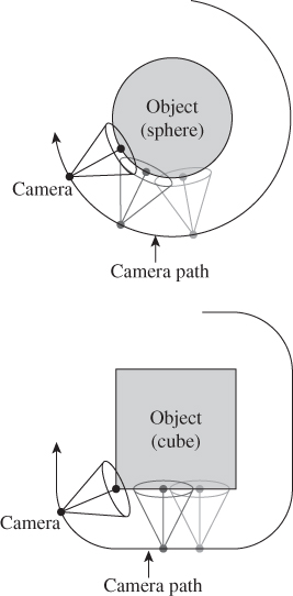
Figure 21.16: The hovercam moves the camera in a way that maintains constant distance from an object of interest. (Courtesy of Azam Khan, ©2005 ACM, Inc. Reprinted by permission.)
Glueck et al. [GCA+09] demonstrate how to improve the output side of interaction to make it easier for the user to understand the placement of objects in a 3D modeling system (see Figure 21.17) by showing their relationship to a ground plane (with a multiscale grid to assist in understanding size). This, in turn, is related to work of Herndon et al. [HZR+92], in which shadows of an object are projected on three walls, and the user can drag the shadow on any wall to induce a corresponding motion of the object (see Figure 21.18).
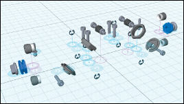
Figure 21.17: Position pegs give cues about the vertical position of objects. Transparent peg bases indicate objects below the plane. Pink pegs, like the one closest to the central grid-crossing, represent assemblies rather than individual objects. (Courtesy of Michael Glueck and Azam Khan ©2009 ACM, Inc. Reprinted by permission.)
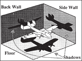
Figure 21.18: Dragging any one of the three “shadows” of the airplane makes the airplane itself move. (Courtesy of the Brown Graphics Group, ©1992 ACM, Inc. Reprinted by permission.)
All of these techniques show off possibilities for improved navigation and manipulation in a particular context (3D CAD and modeling); for navigation in a 3D environment (e.g., in video games) rather different approaches make sense. In CAD, for instance, you may want to be able to pass through surfaces to reach hidden surfaces on which you will then perform further operations, while in video games, it’s typical to prevent players from passing through walls, for instance, and the control is often primarily 2D (forward-back and turn-left-or-right), with height above the floor determined by typical human dimensions. While generally understood camera and motion and object controls may evolve (just as some standard controls have evolved in 2D), we anticipate that application- or domain-specific controls will continue to be developed.
The form of interaction is also dependent on the device you’re using: A user in a virtual reality system typically adjusts the view by moving his/her head and body, although there are many alternatives, like the World-in-Miniature approach [PBBW95], in which the VR user can hold in one hand a miniature version of the world, and move a miniature camera with the other, thus establishing a new point of view for the full-size world.
In some contexts, camera control can be inferred from other aspects of the application. He et al. [HCS96] describe a “virtual cinematography” tool that uses various film idioms to automatically choose views of scenes containing multiple interacting people. For instance, in a film, when two people begin talking to each other, we typically see them both in profile; as the conversation proceeds, we typically see jump cuts between reciprocal over-the-shoulder views. Idioms like this can be used to automatically place the virtual camera in a scene with interacting people, or to assist in virtual storytelling, etc.
In general, the success of these methods can be characterized by context integration and expression of intent and the integration of expert knowledge into interfaces. For camera control, for instance, the viewer typically doesn’t really want to dolly the camera. Instead, she wants to get a closer look at something; dollying the camera is a means to an end. The Unicam system provides a gesture to say, “Give me an oblique view of this object from slightly above it,” for instance, and generates the camera transition to that view automatically. Similarly, the virtual cinematography system incorporates expert knowledge into the design of view transitions so that the user need not consider anything except “which person to look at.” In general, there’s a cognitive advantage to interfaces that let a user express intent rather than the action needed to achieve that intent.
Surprisingly often, the technology of interaction is closely tied to the rest of graphics. Pick correlation, for instance, is most easily implemented with a ray-scene intersection test, the very same thing we optimized for making efficient ray-casting renderers. Keeping a virtual camera from passing through walls by surrounding it with a sphere that’s constrained to lie in empty space uses the underlying technology of collision detection and response to ensure that the sphere doesn’t pass through any scene geometry.
If you are interested in making interfaces for video games, the best source we know is Swink’s Game Feel [Swi08]. It discusses the problem of how to make an interface that “feels good,” both analyzing successes and failures, and giving prescriptive guidelines for design.
For inspiration about user interfaces and how humans approach them, read Norman’s The Design of Everyday Things, which takes Gibson’s notion of affordances [Gib77] and applies it in the context of human-machine interaction.
For 3D spatial interaction techniques that go beyond those described in this chapter, Bowman et al. [BKLP04] give good coverage. Olsen [Ols09] discusses interactive system design that’s not restricted to games, and is firmly hands-on, with good algorithmic and mathematical details. The classic text for those who want some grounding in user-interface design without making a career of it is by Schneiderman et al. [SPCJ09].
21.9. Exercises
Exercise 21.1: A variant of the trackball interaction works like this: The initial click is at some point P of the image plane; the mouse is currently at some point Q. The center of the object is at C, which is assumed to not be on the image plane. The vector (Q – C)×(P – C) serves as an axis for the rotation, with the amount of rotation made proportional to || Q – P||. It’s nice if the proportionality constant is chosen so that for small drags, at least those that start on the line between the eyepoint and C, the rotation resembles the rotation provided by the virtual sphere interaction. The advantage is that there’s no special-case handling needed if the drag goes off the transparent sphere. Implement it to see if there are any obvious disadvantages. Can you easily spin the object around the eye-to-object axis?
Exercise 21.2: The arcball has the property that a sequence of drags from A1 to A2 to A3 to ... An has the same net effect as a drag from A1 to An. We could therefore treat each mouse-drag step as its own operation and update the controlled object’s transformation at each instant, with no need to remember the initialTransform. Can you think of any disadvantages of this approach?
Exercise 21.3: Think about your favorite map-viewing software. Imagine that you have a route between your home and that of a friend who lives 500 miles away. You want to follow that route. Near your home, the route may involve several small streets, but soon you’ll get on a major highway and remain there for some time, eventually doing some small-scale navigation again at the end as you approach your friend’s home.
(a) Design an interface that lets you follow the route conveniently from end to end.
(b) Suppose that you’ve located your home on the map, and have marked it, and now you want to locate your friend’s home and mark that so that the route-finding software can find a good route. You could enter your friend’s address, but navigating visually could be faster, especially on a mobile device. You’ll probably want to zoom out, find your friend’s city, focus on it, zoom in, etc. Can you design a cursor-based interface to achieve this without separate steps (i.e., zoom out, then translate, then zoom in)? Hint: Consider adapting the scale of the view depending on the magnitude of the current motion.
Exercise 21.4: Adapt the photo manipulator so that if the two contacts are moved sufficiently, the photo is rotated clockwise or counterclockwise by 90° about the midpoint of the contacts. You might, for instance, check whether the vector difference between the contacts is rotated more than 60° from the initial vector difference, and treat this as a cue to rotate. Having made this rotation, when should you rotate back to the original position? Why does a 60° threshold make more sense for starting a manipulation than a 45° one?
Exercise 21.5: Implement the translation and rotation parts of Unicam, but replace the dollying adjustment with one where each unit of vertical cursor movement multiplies your distance to the object by some constant ρ < 1. You’ll have to decide how close you should come to the object if the user drags from the bottom to the top of the view. Compare this “logarithmic” version to the linear version of Unicam, and discuss which is preferable, and why.
Exercise 21.6: Enhance the photo-manipulation application so that the user can place two fingers on the photo, and when she moves her fingers, the photo translates and (nonuniformly) scales to maintain the contacts at the same point of the photo. Contrast this to the uniform scaling operation we described.
Exercise 21.7: Consider a basic drawing program, in which the user may draw points, lines, rectangles, ellipses, etc. How would you design the interaction with elements for a multitouch environment? In conventional drawing programs, one can resize a rectangle by dragging any corner, but with a modifier key (like CTRL) held down, the resizing is restricted to preserve the rectangle’s aspect ratio. Do you think such control-limiting operations are more or less important in a multitouch context? Explain.
Exercise 21.8: The photo-sorting application has a front-to-back order on the photos: The last one loaded from the photo directory is on top. Describe some approaches to adding the ability to reorder the photos front to back in a seamless way.
Exercise 21.9: We implemented the virtual trackball by comparing the current position to the initial position and computing a rotation based on that difference. We could instead have implemented an incremental version, in which each cursor motion is interpreted as representing a separate tiny rotation from the prior cursor position to the current one, and these tiny rotations are accumulated. Implement this, and click on the frontmost point of the interaction sphere, then drag a small circle around that frontmost point, and finish by returning to the frontmost point. Does the cube return to its initial position? Do you personally prefer the differential or the integral version of this interaction?
Exercise 21.10: Write down, in as much detail as possible, the conceptual, functional, sequencing, and lexical design for the virtual sphere interaction.
Exercise 21.11: Write a first-person game controller. The game-play area consists of a large room populated by cylindrical poles of various radii, and you’re playing “tag” with several other players, each of whom has a controller like yours, and an avatar that’s a colored sphere. One player is “it,” and tries to tag another player. Tagging a player happens when the avatar spheres touch. (They cannot interpenetrate, or pass through walls or poles.) When the player who is “it” tags another player, that player becomes “it” and the former “it” becomes untaggable for two seconds. Your challenge is to make an effective controller using whatever device you have: a keyboard, a mouse, a touchpad, etc. You should justify your design decisions. The game setting is loosely sketched here so that you are not too constrained: You can create the game in a small room with fat poles to make navigation difficult (because the avatar spheres barely fit between them), or in a room with no poles at all. Construct a world, and then design your controller and discuss how your controller design is influenced by the game-play world.