After you place an order for a T1, be prepared to wait. Avoiding crosstalk on T1 circuits requires that the telco carefully select the wire pairs in a conduit. Repeaters must be adequately separated so that they do not interfere with each other, but must be close enough together to regenerate and recondition the signal. Line cards may be needed at each CO involved. Delays of a month or more from the initial promised date are not uncommon with the installation of high-speed links.
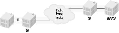
All the waiting does offer you the opportunity to gather the equipment you need and nail down the configuration. When you’ve ordered the circuit, the telco will give you the basic configuration information (line coding, speed, and build out). T1s are priced based on distance. To save money, you could purchase a T1 that links to the nearest entry point to a public data network, such as the telco’s regional frame relay net. This is illustrated in Figure 7-1. You’ll need to find additional configuration information for connections that are not made directly to the ISP.
A telco technician will come to your site to connect the circuit. After the telco brings the line from the CO to the building, the technician installs a jack of some sort, which is often called the demarc. Anything beyond the demarc is up to you (and your ISP) to sort out, while anything up to the demarc is the telco’s responsibility. As part of this process, the technician may need to speak with somebody at the CO. If possible, make sure there is a phone handy near the place where the demarc is to be installed.
If the telco entry point into the building is not convenient for you, an extended demarc is the solution. Convenience may at times be a legal matter, too. Office buildings may have only one telco closet, even if there are multiple businesses in different suites. In such situations, using an extended demarc is required to keep as much control as possible over your network infrastructure. The most likely problem with the wiring in an extended demarc is near-end crosstalk (NEXT), caused by the difference in signal levels between the transmit and receive pairs in the extended demarc. When the difference between the two is 7.5 dB or greater, inductive coupling of the transmit pair and the receive pair can cause a ghost of the stronger signal on the weaker pair. At the CSU/DSU, the transmission will be a full-strength, 0 dB transmission with a peak voltage difference of 6.0 volts, but the received signal will be attenuated by the extended demarc wiring. If the signal on the receive pair is -7.5 dB or lower, inductive coupling between the transmit pair and the receive pair may cause crosstalk and corrupt data.
You can combat crosstalk by using cable with appropriate shielding. Most modern LAN wiring uses Category 5 unshielded twisted pair (UTP) cable, which relies on tightly twisting the component wires of a pair together so that interference affects both component wires of a pair equally. In T1 applications, UTP is subject to interference if the difference in strength between the signals on adjacent pairs is 7.5 dB. Adding shielding dramatically improves the picture because it prevents signal leakage from pairs that carry a strong signal and helps resist inductive coupling in pairs that carry a weaker signal. Individually shielded twisted pair (ISTP) cable wraps each pair of wires in a foil shield, then adds drain wires to help terminate the shields. Figure 7-2 contrasts UTP and ISTP.
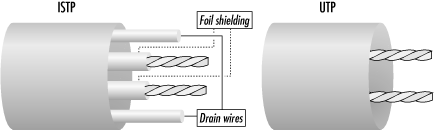
Shielded cable prevents crosstalk in nearly all circumstances, but it costs more and is more complicated to work with because the shield foil must be peeled back and the drain wires terminated. Unshielded cable can be used when the signal differential is less than 7.5 dB. Most smart jacks will output a 0 dB signal, so unshielded cable is fine for extensions of up to the 1000-1200 foot range. Beyond those distances, shielded cable must be used. Digital cross-connects between devices such as a PBX and an add/drop CSU must be less than 655 feet, so unshielded cable can be used without a problem in most cases.
After the demarc is installed, the technician may hook up a small box to test the line. At the CO, the line is looped back to your location. Any bits sent down the line to the CO should bounce back without error. Test equipment sends standard patterns down the line and counts errors on the return path. Severe errors require that the technician speak with other telco personnel so the telco can correct any problems on the line.
If all goes well, the telco should eventually pronounce the line good and affix a sticker to the demarc with configuration information, such as the circuit ID. Depending on the telco, the sticker may also include an installation date and other information. Even though the end span is installed at your location, the entire line may not be up because the full circuit may need to wend its way through other COs and the ISP-side end span may need to be installed. Your end span is frequently the final piece, though, because the telco may take many T1 access lines from the same area and multiplex them into a higher-speed line, such as a T3, to the ISP’s point of presence.