The world hates change, yet it is the only thing that has brought progress.
One of the complaints that many data-networking veterans have when venturing into the telecommunications world is the bewildering number of acronyms and strange terminology that await them. Before diving into small details about different components of a T1, some background with the technology is essential. This chapter introduces the terms and basic structure of a T1 circuit so that successive chapters can delve into detail on the most important components.
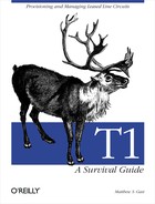
Figure 2-1 shows a high-level diagram of the link between an Internet service provider (ISP) and a customer, delivered over an archetypal T1 circuit. Due to the number of components required to build a T1, Figure 2-1 is divided into four parts. In the classic case, two wire pairs, one each for reception and transmission, combine to form a T1. Devices called repeaters are used to allow for transmission of the signal over long distances. Signals degrade as they travel along the path, but repeaters recover the digital input data and retransmit the digital data at full strength. In theory, this allows for perfect transmission of data because a digital signal can be perfectly recovered and an exact bit-for-bit copy sent on to the destination. Repeaters divide the circuit into a series of spans, or paths between repeaters.
As technology marched on, the technology used to deliver T1 circuits changed. In most locations, only the end span connecting subscribers to the central office (CO) is delivered over the four-wire copper interface. Fiber-optic transport systems such as SONET are usually used to move data between the two COs at each end of the circuit. Among its many benefits, SONET provides protection switching. If a link in a SONET network fails, protection switching diverts connections onto a backup path within milliseconds.
Once the span reaches the near-end CO, it is routed over the telco’s network to the far-end CO. Between all the COs, redundancy and spare capacity is provided by the telco through SONET protection switching. Network outages due to telco equipment failure are far more common on the repeatered copper spans than on the SONET rings. It is not uncommon for these spans to be interrupted by construction equipment. When construction activity breaks up the end spans, protection switching is not available because only one path exists from the customer location to the CO. This type of interruption is frequently called backhoe fade by network engineers to distinguish it from other types of signal fading on the T1 line.
Figure 2-1 (a) shows the end span on the local end, which is the most familiar part to subscribers. The computer, LAN, and probably even the router are nothing new and exciting—these are components that you probably have looked at many times before. Most likely, some form of Ethernet is used as the LAN medium, and the path from a computer to the router is a familiar one with well-known concepts such as MAC addresses, ARP, and so forth. In simple situations like that in Figure 2-1 (a), routers are not complex beasts, either. Any packets addressed to distant parts will be relayed to their destinations over the T1.
Past the router, the territory gets decidedly less familiar, even for those of us who deal regularly with telecommunications. Many network engineers have nearly endless opportunities to break Ethernet networks, but WAN lines are much more mysterious, so they tend to be left alone.
A serial connection joins a router to a T1. Serial communications make sense, after all: the T1 takes a stream of bits from Point A and moves them (in order, we hope) to Point B. T1s run quite fast, especially when compared with pedestrian serial standards such as the ubiquitous RS-232 on personal computers. Typically, the router-to-T1 connection is made using the V.35 serial standard. For the purposes of establishing the V.35 serial circuit, the router is considered the data terminal equipment (DTE) and the CSU/DSU is considered the data communications equipment (DCE). As with modems, DTE simply means “generator of data,” and DCE means “responsible for sending data somewhere else.”
V.35 is an electrical specification, so it specifies voltages and currents, but does not specify what the connector looks like. The most common connector is the Winchester block, which may be simply called a Winchester connector, an M-block connector, or an MRAC-34 connector. (Several people I know think that the Winchester connector looks like an instrument of torture. Judge for yourself: Figure 2-2 shows one.) Nothing prevents the V.35 electrical signal from being transmitted over a different type of connector, though. Some equipment uses 25-pin D-sub cables, which are extremely common connectors in the personal computer world. Proprietary connectors are also not unheard of.

To connect a data network to the telephone network, you need a device called a CSU/DSU. CSU/DSU stands for Channel Service Unit/Data Service Unit.[6] As the name implies, the CSU/DSU includes two separate functions. The DSU is responsible for handling the V.35 interface with the router. The CSU handles connection to the telco network; the reason for the name “channel” in CSU will become apparent later.
In terms of the OSI model, CSU/DSUs are layer 1 devices that translate the V.35 signals into telco network-compatible signals. When these signals are sent on the telco network, some degree of framing across the network is needed, but the details are not relevant to this chapter’s high-level overview.
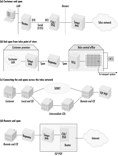
In addition to a V.35 port, the CSU/DSU has a network interface (NI) to hook up to the telco network. A variety of AT&T technical reports first specified characteristics of the network interface. To create a true multivendor interface, the American National Standards Institute (ANSI) later undertook standardization efforts and published them as ANSI T1.403. The T1 interface uses four wires: one pair for transmit and a second pair to receive. Figure 2-3 shows CSU/DSU network interfaces.
Ensuring cable compatibility is easy. Standard jacks are registered with the FCC and given RJ (registered jack) numbers. T1 network interfaces follow the RJ-48X standard. RJ-48X jacks contain shorting bars, which automatically loop the line back if the cable is unplugged from the jack.
CSU/DSU equipment uses one of two methods to connect to the T1 span. Some equipment uses a second RJ-48 jack and a cable with two modular connectors. Other equipment uses a DA-15 jack at the CSU/DSU end and a modular connector at the line end.
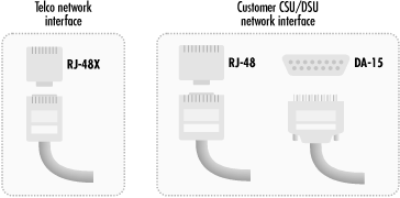
Cable runs from the CSU network interface to the demarc, a term short for demarcation point. You are responsible for repairing problems on your side of the demarc, and the telco is responsible for anything beyond the demarc. Frequently, the demarc is the telco’s Network Interface Unit (NIU), nicknamed a smart jack. Smart jacks perform a variety of network maintenance functions and make it much easier for the telco to manage the network remotely. Figure 2-4 shows a smart jack.
The smart jack is located with other telephone equipment at your building. It is placed where it is convenient for the architect (and maybe the telephone company), but those considerations do not necessarily have anything to do with the network. In situations where the smart jack is far away from the CSU/DSU location in a machine room or network operations center (NOC), wiring must be run from the demarc at the smart jack to the CSU/DSU location. This is called an extended demarc. Wiring is extended from the smart jack to a more convenient location, where it is terminated by what looks like an overgrown telephone jack. (I once worked at a company that rented space in a multitenant office building. The telco closet was used for the entire building, which meant that anybody in the building who ordered a T1 needed to install an extended demarc.)
Because of their small, squarish appearance and off-white color, these jacks are frequently referred to as biscuits. Extended demarcs can be tricky to get right and are a major source of problems with T1 circuits. Wiring an extended demarc is not as simple a task as installing an Ethernet drop. In many cases, shielded cable must be used to preserve signal quality. Additionally, the pinout for the smart jack interface is different from other data-communications pinouts, so unless the installer is familiar with the pinout, the line will pick up outside interference. For a fee, the telco will typically install the extended demarc for you. Unless you have extensive experience installing extended demarcs, pay somebody else to do it right. In the long run, it will save time and money. Figure 2-5 illustrates an extended demarc.

From the smart jack, the connection runs to the nearest telco central office. Depending on the facilities the telco uses to provide the wiring, the end span may be over a four-wire repeatered line or it may be partially run over a metropolitan fiber network. Figure 2-1 (b) shows a T1 using repeaters the entire way to the CO. At the CO, the line terminates at the CO-side equivalent of a CSU, called an Office Channel Unit (OCU).
T1 specifications allow each span to have up to -30 dB loss before the signal is unintelligible. (Actually, the specifications allow 33 dB, but the last 3 dB serve as a safety factor.) To keep signal loss at or below this level, repeaters are required at approximately 6,000-foot intervals. (One unsubstantiated legend suggests that the repeater interval is where the “1” in “T1” comes from—repeaters are required at one-mile intervals.) In the purely copper scenario in Figure 2-1 (b), the parts of the line that are provided using a four-wire interface must be composed of carefully selected pairs in a conduit to avoid crosstalk and distortion. Additionally, the line must be properly conditioned for T1 service, which means removing a variety of devices such as bridge taps and load coils that improve the quality of analog voice service.
Tip
Extensive line conditioning, cable selection, and repeater installation are all expenses that increase as the length of the span increases. As a result, T1 pricing typically depends on the distance of the span, and installation time may be long.
Even if most of the T1 is run over fiber, the fiber-optic network multiplexors must be configured to create a 1.544 Mbps digital transmission channel through the fiber-optic network. Provisioning a new stream through a fiber-optic network is also a time-consuming affair, though not as bad as eliminating crosstalk between T1 repeaters in the field by careful wire selection in a conduit.
At the CO, the physical line from the customer must be connected to the ISP (if both are served by the same CO) or to the telco’s transport network (which moves the bits from the local CO to the remote CO that serves the ISP). In the very distant past, these connections were physical—wires were spliced together to create a long wire loop between the two locations. Today, logical connections are made with the help of a digital cross-connect system (DCS), which is sometimes called a digital access and cross-connect system (DACS). DCS hardware is essentially a switch. All the lines coming into a CO are connected to the DCS so the incoming digital streams can be logically connected to outgoing streams. DCSs also perform multiplexing functions, so several incoming T1s can be combined and mapped onto a single higher-speed output stream.
Once the input data stream connects to the transport data stream, it can be moved across the telco network to the remote CO, as shown in Figure 2-1 (c). Depending on the telco’s physical infrastructure, this may happen in a variety of ways. In densely populated metropolitan areas, SONET rings may be used to ship the data directly from the local CO to the remote CO. SONET rings can move hundreds of megabits per second or even gigabits per second, but their chief advantage is that they allow for equipment to easily “peel off” the data destined for the local end without having to demultiplex the entire signal. Areas without extensive SONET infrastructures may use a variety of techniques, including simple repeatered copper pairs through intermediate COs. Both approaches are shown in Figure 2-1 (c).
At the remote end, the CO connects the incoming signal from its DCS, to the output path for the T1, to the ISP POP. The remote end of the circuit, shown in Figure 2-1 (d), is quite similar to Figure 2-1 (a). ISPs are responsible for supplying their own CSU/DSUs and routers. Because ISPs may terminate huge numbers of customer-access lines at a particular point of presence (POP), the ISP router will frequently have an integrated CSU/DSU to terminate the line to save rack space.
[6] The CSU and DSU functions are distinct. (Prior to divestiture separate boxes provided each, but the CSU and DSU are always integrated into a single box when T1 is used for data communications.) Because both functions are required to connect data communications equipment to telco networks, they are almost always combined into one box. Even though the functions are equally important and are both needed to connect to the telco network, it is common to hear people refer to the entire unit as either a “CSU” or a “DSU.”