
Data links come in many flavors with widely varying properties. PPP was intended to operate over all types of physical links, so it includes the Link Control Protocol. LCP allows two endpoints of a connection to negotiate encapsulation options when the data link is initialized and can monitor the link quality to ensure that quality is not slowly degrading.
Configuration option negotiation is an interesting departure from other types of negotiations in the networking world. In PPP, the transmitted requests are requests to the remote end on the inbound data. PPP allows the local end to specify what it will receive, not to tell the remote end all the things the local end can send.
LCP uses three classes of packets:
Link Configuration packets negotiate options.
Link Termination packets tear down the link.
Link Maintenance packets ensure continued operation of the link.
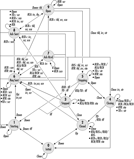
LCP is described as a state engine by the standard. A link may be in one of several states, and certain events cause transitions between the states. Figure 9-6 shows a simplified diagram of the LCP state engine. Each state in the diagram is numbered. For quick reference, these states are also described in Table 9-4:
In this state, the physical link is not yet available, but has been administratively activated. This state might correspond to an asynchronous modem waiting for its carrier signal.
This is a complementary state to Starting. Physical connectivity is available, but no administrative action has configured it to pass traffic. This state is common on T1 links because the physical layer becomes active quite soon after the physical plugs are connected.
This state is similar to Closed in that the physical link is up but the logical link is not configured. It is usually entered when timeouts have expired or link termination has been requested. Reconfiguration of the link will not be initiated, but if the peer attempts configuration, LCP will attempt to renegotiate.
When the link has been administratively closed, a Terminate-Request is sent to the peer and LCP enters the Closing state to wait for acknowledgment. Attempts to reconfigure the link are discarded.
This state is similar to the Closing state, except that the link is administratively open. When the link is torn down, LCP is in either the Stopped state or the Starting state. Both of these states allow reconfiguration.
This state is the common entry point for the configuration exchange procedures in LCP. In this state, a Configure-Request has been sent to the peer, but no acknowledgments have been made.
In this state, the outbound link has been configured, but the inbound link configuration is not yet complete. The peer has agreed with and acknowledged the proposal sent by the local end.
In this state, the inbound link has been successfully configured. The peer has sent a proposal that has been acknowledged. Outbound link configuration is still proceeding.
This state is the Holy Grail of LCP states. Once this state has been reached, further negotiations proceed.
Table 9-4. States of the LCP state engine
|
Number |
Name |
Description |
|---|---|---|
|
0 |
Initial |
No physical carrier signal is available and the logical link is administratively closed. |
|
1 |
Starting |
The physical carrier is unavailable, but the link is administratively active. Reconfiguration of the link is possible. |
|
2 |
Closed |
The physical carrier is available, but the link is administratively closed. |
|
3 |
Stopped |
Both the physical and logical links are available, but there is not necessarily any intent to close them. This state can be reached when the link is being terminated or when configuration has failed. Reconfiguration is possible. |
|
4 |
Closing |
The link has been administratively closed; LCP has sent a termination request and is waiting on the acknowledgment before moving to Closed state. No reconfiguration is possible. |
|
5 |
Stopping |
When the peer has administratively closed a link, a Terminate-Request will be received. |
|
6 |
Req-Sent |
A Configure-Request has been transmitted, but no configuration proposals have been acknowledged, either by the peer or locally. |
|
7 |
Ack-Rcvd |
An acceptable Configure-Request has been transmitted and acknowledged to configure the outbound link, but configuration of the inbound link is not yet complete. |
|
8 |
Ack-Sent |
An acceptable Configure-Request has been transmitted and acknowledged to configure the inbound link, but outbound configuration is not complete. |
|
9 |
Open |
This is the goal of the configuration process. When reached, PPP implementations will notify higher layers that it is up. Conversely, when leaving the Open state, it will notify higher layers that it is now down. |
In addition to the states in the diagram, events cause transitions. Table 9-5 summarizes all the events defined by the PPP standard. In response to events, an implementation may also take action. To distinguish between events and actions, events are capitalized in Figure 9-6. If more than one event leads to the same action, they are separated by slashes. For example, any configuration packets received in the Closing state do not cause a state change.
If an event leads to an action, the underlying event is listed, followed by a colon and then the action. Multiple actions are separated by commas. For example, reception of any configuration packets in the Stopped state causes LCP to respond by sending a Terminate-Ack.
Figure 9-6 also makes use of multitailed arrows when the same event in different states leads to the same final state. A Down event in the Open, Ack-Sent, Ack-Received, or Request-Sent state returns LCP to the Starting state. Events have different meanings depending on the layer of the PPP suite at which they occur. An Up event at the LCP layer means that the physical layer has come up, but an Up event at the network layer means that LCP has initialized.
Table 9-5. Abbreviations used in Figure 9-6
To breathe life into the complex state diagram, this section shows how some common operations cause transitions between the different states.
LCP requires administrative action in order to open a link. If no administrative Open is issued, LCP will not perform any configuration negotiations. Instead, it will respond to any polite configuration requests with termination packets. The goal of link initialization is to move from the link-management states into the logical link configuration states. There are two types of link initialization:
- Self-initiated
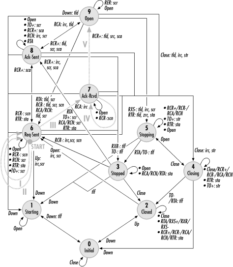
If the link is currently down, both an administrative Open and a physical-link initialization must occur. No matter what the sequence is, a configuration request is sent and LCP moves to the Request-Sent (6) state. Figure 9-7 overlays a self-initiated initialization onto the diagram of the PPP state engine.

- Peer-initiated
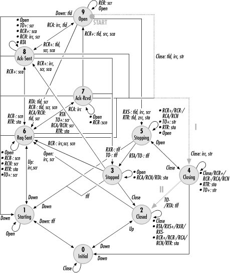
If the logical link was previously stopped, link configuration can proceed from the Stopped (3) state if the peer sends a configuration request. LCP will either acknowledge that request or send a counterproposal, and a configuration request will be sent to propose options to the peer. Figure 9-8 overlays a peer-initiated configuration onto the PPP state diagram.

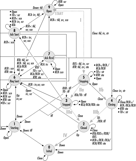
Configuration ends when both sides have agreed on mutually acceptable parameters for both directions. PPP options are like IPSec security associations. Each half of the link can have its own configuration parameters. Configuration requests affect parameters used for the inbound half of a link, and the outbound link direction is negotiated separately. A typical negotiation may go something like Figure 9-9.
Initial configuration parameters on the local side are part of the PPP software’s initialization files. These options are bundled together in a configuration request and sent to the peer.
Each option in the configuration request is examined for compatibility. Some options may be totally unacceptable, while others need to have values adjusted before they become acceptable. Totally unacceptable options may be due to a policy decision made by the device’s owner, such as an ISP requiring authentication on dial-up servers or a software limitation. Show-stoppers are sent back in a configuration reject message.
After receiving the Configure-Reject, the local end must revise its parameter set and eliminate the totally unacceptable options in successive configuration requests. A proposal without the unacceptable options will be received more favorably, but it still may not be ideal. No totally unacceptable options will be included because they were previously rejected, but some options may be included with values that should be changed. Unacceptable values will be sent back in a Configure-Nak counterproposal. Naks include hints, which are values that the peer is willing to accept.
Naks present the local side with a choice: the option can either be omitted entirely so that it reverts to its default, or it can be revised to the hint. The former case may result in another Nak with the hint value, or the default may be acceptable. In the latter case, the new configuration request will be acceptable. The peer will reply with a configuration acknowledgment including all options.
Meanwhile, the same procedure has been happening to configure the link from the peer to the local end. Depending on the set of parameters the peer desires, it may take more or fewer cycles, or convergence may never happen. If each side of the link is configured in such a way that no mutually acceptable parameter set exists, the peers will never be able to negotiate away their differences and the link will stay down. In some cases, the incompatibility may be due to parameters that are the defaults of a particular PPP implementation.
In Figure 9-9, the configuration process starts from the Request-Sent (6) state. Step I includes unacceptable options, so the peer sends a veto (Configure-Reject). After revising its options to be acceptable, the peer retransmits the request in step II. That request is also not acceptable because the values chosen for some options were not acceptable. A third request in step III is acceptable, so LCP moves to the Ack-Received (7) state. At this point, the outbound link is configured. Meanwhile, the peer performs a similar process. Unacceptable options received in step IV result in a counterproposal, which means that the next request received is acceptable. LCP moves into the Open (9) state and PPP proceeds to the next layer.
There are two types of link termination, which work as follows:
- Self-initiated
An administrative link closure moves LCP from an active configuration state to the Closing (4) state and sends a termination request to the peer. Circuit-switched links are torn down at this point, but leased lines remain constantly physically available under normal circumstances. When the termination acknowledgment is received, LCP moves to the Closed (2) state to wait for another administrative opening of the link. Figure 9-10 shows the steps for a self-initiated termination on the PPP state diagram.
- Peer-initiated
When the peer receives a termination request, LCP acknowledges the request, marks the link layer as down, and moves to the Stopping (5) state. Leased lines remain physically available, so LCP needs to wait for the termination timer to expire. Three events are likely to happen at this point: an acknowledgment of the termination, a timeout, or an administrative closing of the link. Depending on which of the three events occurs, two paths may be taken; these paths are illustrated by the “a” path (termination acknowledgment or timeout) and the “b” path (administrative closure) in Figure 9-11. Following link closure, the underlying physical layer may be torn down, in which case LCP moves to the Initial (0) state. On leased lines, the physical layer typically remains available, so LCP remains in the Closed (2) state .
LCP is transmitted in standard PPP frames as protocol 0xc021. Although LCP provides for option negotiation, which may affect the stuffing procedures used for transparency, all LCP frames are sent using the default values for all parameters. This guards against the two ends getting out of synchronization on which parameters to use and LCP becoming unintelligible as a result.
Figure 9-12 shows the format of a generic LCP packet. LCP on the wire uses a header composed of a type code to distinguish between LCP frame types, an identifier, and a length field, which is the length of the LCP data field in bytes. Identifiers are 1-byte numbers used to match up requests and responses. LCP type codes are defined in Table 9-6.
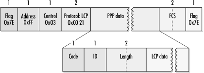
Table 9-6. LCP type codes
|
Code |
Type |
Description |
|---|---|---|
|
0 |
Rarely used vendor extension mechanism specified in RFC 2153. | |
|
1 |
Proposed set of nondefault configuration options to a peer, with all options enclosed in one frame. | |
|
2 |
Acceptance of a set of options; includes a copy of the proposal for verification. | |
|
3 |
Counterproposal used when the values assigned to some options are not acceptable. Unacceptable options are modified with suggestions for new values. | |
|
4 |
Options that are not recognized or are unacceptable with any value are noted in the data field of the Configure-Reject. Configure-Rejects are also used for Boolean options with unacceptable settings. | |
|
5 |
Sent by one side to request that the link be terminated. | |
|
6 |
Used in response to Terminate-Requests to acknowledge that the link should be torn down. | |
|
7 |
LCP does not use version numbers in packets because unknown codes may always be replied to with a Code-Reject, which is used to indicate that the code in a received LCP packet is unknown. | |
|
8 |
Once a link is opened, any unknown protocols are rejected with Protocol-Reject packets. | |
|
9 |
Used like ICMP echo request to test link connectivity. Also used in link quality monitoring. | |
|
10 |
Sent in response to LCP Echo-Request packets. | |
|
11 |
The receiver of a Discard-Request throws away the packet. Discard-Requests may be used for debugging or link-connectivity testing. | |
|
12 |
Identifies sender in an implementation-dependent manner. Text may include software package name and version, hardware platform, or any information the programmer who wrote the PPP implementation would find useful. | |
|
13 |
Rarely used message defined in RFC 1570 to notify a peer of the time remaining in a session. | |
|
14 |
Used in a compression protocol to request reinitialization of compression routines. | |
|
15 |
Acknowledges compression reinitialization. |
Configuration frames are the workhorses of LCP. LCP’s main job is to negotiate link options, which is done as the LCP implementations on both sides of the link exchange proposals and counterproposals until they reach mutually acceptable option sets. Each configure packet has an identification number that is supposed to allow matching of requests and responses. The field, generally, can be used for matching requests with responses, though bugs or implementation errors may make this impossible. Do not make any assumptions based on the identification field when looking at LCP traces. Figure 9-13 shows the formats of all four configuration messages.
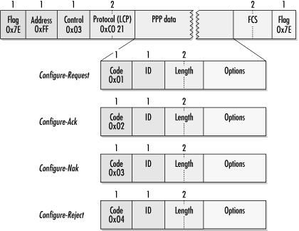
LCP uses Configure-Request frames to propose changes to the default options on a link. The data portion of the Configure-Request lists a set of nondefault options. Implementations do not need to send default values as part of the option set. Option coding is presented in detail later in this chapter.
Configure-Reject frames are used when unacceptable options are present in the proposed configuration in the Configure-Request. An option may be unacceptable because it is not implemented or because it is unrecognized. It is possible, for example, to create a minimally compliant PPP implementation that simply rejects any nondefault options, though such an implementation would not be very useful.
After receiving a Configure-Reject, a system resends a new Configure-Request with a new identification number, omitting any unacceptable options. These would be options that are acceptable but have values that could be improved upon result in a Configure-Nak. Configure-Naks include only the options that need to be changed. To assist in the negotiation process, Configure-Naks suggest new acceptable values to the peer; these suggestions are known as hints. When a desirable option is not present, it is legal to include the desired (but unrequested) option in an unsolicited Configure-Nak. Not all implementations cope well with unsolicited Configure-Naks.
When all is well, a Configure-Ack is returned to acknowledge the Configure-Request. It includes a copy of all the options from the Configure-Request for verification.
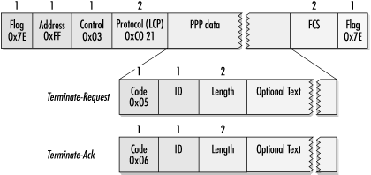
Two types of termination packets are used by PPP. Terminate-Request packets are sent to request link closing. After sending a Terminate-Request, LCP waits for a Terminate-Ack. If no Terminate-Ack is received within a timeout period, the link is torn down. This is illustrated in Figure 9-14. Termination requests may include text describing why the link was torn down. Generally, this string is printable ASCII.
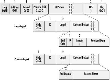
LCP uses code- and protocol-rejection messages to indicate to a peer that the received code or protocol is invalid. To assist in identifying the offending message, the received frame is included in the data portion of the rejection frame.
Code-Reject is the mechanism by which LCP avoids using version numbers. Older implementations send Code-Reject messages in response to new protocol options, providing a straightforward interoperability mechanism. In a Code-Reject packet, the data portion contains the packet that was rejected, beginning with its information field. Both the link layer headers and the FCS are omitted, and the entire Code-Reject message must fit within a single frame. If the resulting Code-Reject is larger than the link Maximum Receive Unit (MRU), the frame is truncated to fit.
LCP must have completed negotiating before sending protocol-rejection messages. Protocol-rejection messages are used to indicate that an entire network layer protocol is not supported by a PPP implementation. If a peer requests to configure an unsupported protocol, a Protocol-Reject message is sent in response. Protocol-Rejects are fairly common and perfectly acceptable in PPP negotiations. They might occur, for example, if a dial-up link attempts to negotiate IP, IPX, and NetBIOS. Dial-in servers at Internet service providers would reply to the IPX and NetBIOS configuration requests with protocol-rejection messages because those protocols are not generally supported by ISPs. Figure 9-15 shows Code-Rejects and Protocol-Rejects.
Echo-Request and Echo-Reply are used to check link integrity, much as ICMP echo requests and echo responses are used by network administrators for IP-level connectivity. Discard-Request is relatively uncommon, but may be used during testing. Figure 9-16 shows the format of the link-integrity frames.
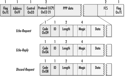
Echo messages are used in the same way that SLARP is used for link-integrity verification. Periodic echo requests are sent, and if several transmission intervals elapse without receiving a reply, the link is torn down. Echo timers are nearly always configurable because of the drastic variation in PPP link speeds; a single fixed interval could never hope to satisfy the demands of dial-up users and administrators overseeing SONET networks. Priority is often given to these messages because of their urgency. It is better to drop a frame of user data than to tear down and reestablish the link after a timer was allowed to expire. To provide for link verification, echo requests in Multilink PPP (MP) are transmitted without going through the MP encapsulation routines.
To aid in debugging, RFC 1570 defined the Identification message. After the customary code, length, and magic number fields, an implementation-defined text string is transmitted. Figure 9-17 shows the format of the LCP Identification message.
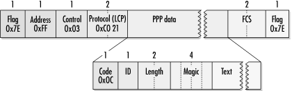
When it is implemented, the information field contains information that is helpful in debugging. Most implementations include the sender’s software version and hardware platform.
The Time-Remaining (13) message, also defined in RFC 1570, is rarely implemented. Reset-Req (14) and Reset-Ack (15) are used with the PPP Compression Control Protocol. Data compression is useful only when the CPU power on both ends of the link is dramatically greater than the link speed. When T1 access lines are used, the terminating device is usually an access concentrator that must share its CPU power between a large number of incoming connections, so access concentrators typically do not have the spare computational power to run compression.
Code 0 was initially reserved, but was allocated to vendor extension in RFC 2153. Many vendors use unallocated options rather than vendor-extension mechanisms.
Much of LCP’s work is done in negotiating the link-configuration options. Link-configuration options are embedded within the data field of the configuration proposals. Every option has a corresponding type code and is embedded in LCP packets with its code, total option length, and any option data, as in Figure 9-18, which shows several options within a Configure-Request. Some options are enabled or disabled but have no data.
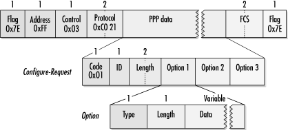
Several LCP options are listed in Table 9-7. Common options are treated in more detail in subsequent sections. During LCP negotiation, frames are transmitted with the default options engaged.
Table 9-7. LCP option codes
|
Code |
Type |
Description |
|---|---|---|
|
0 |
In addition to proprietary type codes, RFC 2153 specified vendor-proprietary option codes. In practice, most vendors simply choose unallocated numbers rather than using the RFC 2153 procedure. | |
|
1 |
An extremely common option used to specify the maximum frame size the peer is willing to receive. Often used to tune performance. | |
|
2 |
As its name implies, the ACCM is not used on synchronous links. | |
|
3 |
Used to select the protocol that will authenticate peers to each other. | |
|
4 |
Used to negotiate link quality monitoring to ensure adequate link performance. | |
|
5 |
Used to guard against bringing up PPP on looped-back physical links. | |
|
7 |
Negotiated to shrink the protocol field from 2 bytes to 1 to save transmission bandwidth. Very useful on asynchronous lines. | |
|
8 |
Negotiated to shrink the address and control fields in the PPP frame. | |
|
11 |
Described in RFC 1663, Numbered Mode allows PPP implementations to maintain a window and ensure reliable delivery. | |
|
17 |
Negotiation of this option sets up Multilink PPP (MP). Appendix B discusses MP in detail. | |
|
18 |
Multilink Short Sequence Number Header Format |
Negotiated with MP; see Appendix B. |
|
19 |
Negotiated with MP; see Appendix B. | |
|
22 |
Proprietary multilink protocol designed by Ascend and specified in RFC 1934. For details, see Appendix B. |
To indicate the maximum frame-data size an implementation is able to receive, it can transmit the MRU to its peer. The format of the MRU option is shown in Figure 9-19.
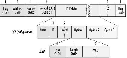
Headers and framing do not count toward the MRU. All implementations must be able to support an MRU of 1,500 bytes. Systems may request the use of larger MRUs for more efficient transmission of bulk data, but accepting a large MRU does not require its use. An implementation could acknowledge a requested MRU of 4,096 bytes but then only send 1,500 byte frames and still be within the letter of the specification. Smaller MRUs may make interactive traffic more responsive at the loss of bulk data transfer capacity.
PPP provides the capability of monitoring link quality. Quality monitoring is enabled with the Link Quality Monitoring (LQM) option in LCP, shown in Figure 9-20. It includes a quality protocol number and optional data.
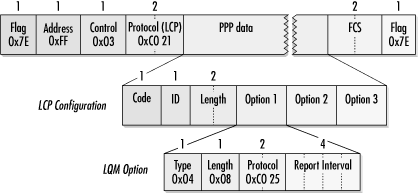
Only one quality-monitoring protocol is currently defined, and it is not widely implemented. RFC 1989 specifies PPP protocol 0xc025, the PPP LQM protocol. Figure 9-21 shows the LCP option used to propose the use of this protocol, including the 4-byte report option interval. The specified number is the maximum time between link quality reports. Other quality protocols may be developed in the future, in which case the protocol identifier would be different and the data after the protocol identifier would be defined by the new protocol.
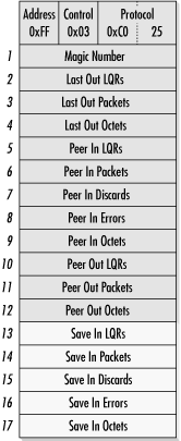
A link quality report is a series of quantities, each of which is 4 bytes long. When quality reports are received, 5 bytes with locally generated statistics are appended. Quality reports allow each side of the link to monitor loss based on the received statistics and take action based on those reports. Any actions that may be taken based on the data are implementation-specific.
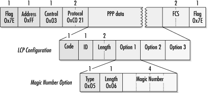
Magic numbers are a part of the initial RFC 1661 specification. The magic number option is illustrated in Figure 9-22. Magic numbers are used to detect looped-back links and data that is mistakenly sent back. Telcos may place loopbacks on T1 lines at any repeater that responds to the loopback commands in the T1 facilities data link. When the telco places these loopbacks, it is often up to customers to detect them and call the telco to take corrective action.
When negotiation procedures use magic numbers, the goal is a mismatch between the last transmitted number and the last received number. Magic numbers are chosen randomly on both sides of the connection, so any two peers are unlikely to choose the same number. Upon reception of a Configure-Request, the magic number is compared to the last transmitted magic number. If they do not match, it is proof that the line is not looped back.
Matching magic numbers, or magic number collisions, indicate that there is a possibility that a link is looped back. To ascertain whether this is the case, a Configure-Nak with a different magic number is transmitted. When the next Configure-Nak is received, the transmitted magic number is compared to the received magic number. Different numbers indicate a straight-through line and configuration proceeds. If a collision is detected, a looped-back line is more likely. Looped-back links are detected by looking for a pattern of send Configure-Request, receive Configure-Request with identical magic number, send Configure-Nak with new number, and receive Configure-Nak with new number. After several cycles, it is almost certain that the line is looped back. Magic numbers may also be used in conjunction with LCP Echo-Requests and Echo-Replies to detect lines that are looped back in mid-session. When systems do not negotiate magic numbers, they use zero instead. Some PPP implementations are unable to use magic numbers.
RFC 1663 described Numbered Mode as well as the configuration option to enable it, shown in Figure 9-23.
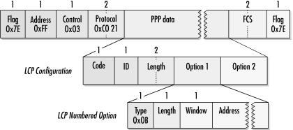
RFC 1662 framing specifies that PPP frames be sent using the unnumbered mode control information. Numbered Mode sends frames using Link Access Procedure, Balanced (LAPB). The window is used to select the transmission window size. LAPB is derived from HDLC, and the window is interpreted accordingly. When this option is used, the window size is typically set to either 8, for basic HDLC operation, or 128, for extended HDLC operation. When this option is negotiated, an open PPP link uses the HDLC address specified by the address field to send and receive data links, and the control field is reinterpreted according to LAPB specifications. Sending the appropriate addressing information allows the enabling of ISO-specified multilink procedures.
When Numbered Mode is activated, higher layers are protected from frame loss by a reliable data link layer. As frames are buffered and retransmitted, though, higher layers see a wide variance in delivery time and may adjust transmission rates accordingly. TCP is especially susceptible to variances in transmission time without packet loss. Numbered Mode should be used only when the cost of lost packets drastically exceeds the retransmission cost; PPP with the Compression Control Protocol is one such case. Asynchronous modems incorporate error detection and correction, which makes Numbered Mode redundant overhead. Digital transmission facilities have low enough bit-error rates that it is not usually necessary unless the underlying medium is a noisy radio link.
The MRRU option enables Multilink PPP (MP), specified in RFC 1990. The SSN and ED options modify the behavior of MP, but only the MRRU option can enable multilink operation. MP works by breaking packets into smaller fragments for parallel transmission over several links and reassembling the link layer fragments at the remote end. MP is described in more detail in Appendix B.