
Every thought is an afterthought.
Managing far-flung networks requires a helping hand. Most network administrators, when given the tasks of running large networks with many leased lines, turn to SNMP, the Simple Network Management Protocol. This appendix presents an overview of two MIBs that may be useful to network administrators with extensive T1 deployments.
RFC 2495 defines the MIB for DS1, DS2, E1, and E2 interfaces. This section will consider only the DS1 portion of RFC 2495.
RFC 2495 was written at the time when a draft revision of T1.231 was working through the ANSI standards process. Some of the definitions in RFC 2495 are based on early drafts of T1.231 and thus are not fully consistent with T1.231. These differences are important because data communications equipment vendors implement the RFC, but telecommunications equipment vendors implement the ANSI specifications. Here are some differences:
RFC 2495 defines the out of frame (OOF) defect in exactly the same way that ANSI T1.231 defines the severely errored framing (SEF) defect. In practice, this is only a minor difference because SEF defects are nearly always accompanied by ANSI-defined OOF defects.
The definition of a severely errored framing second (SEFS) in RFC 2495 is equivalent to the ANSI definition of a severely errored framing/AIS second (SAS-P).
RFC 2495 uses the term “bursty errored second” to refer to ANSI’s errored second type B.
As RFC 2495 defines an errored second, bipolar violations are also an underlying cause. ANSI defines an errored second on an SF-framed link as a 1-second interval that contains framing bit errors, controlled slips, severely errored framing (identical to the RFC’s out of frame defect), and AIS defects. RFC 2495 adds bipolar violations to the list of triggers. There is no difference between the RFC 2495 and ANSI definitions of an errored second on an ESF-framed link.
The RFC 2495 definition of a severely errored second for SF-framed links does not include AIS defects, but does label a second severely errored if 1,544 or more line code violations occur. Both definitions are identical for ESF-framed links.
RFC 2495 defines degraded minutes (DMs), which measure when the bit error rate is higher than expected for modern digital facilities (10-6).
RFC 2495 specifies that defects must be present for between 2 and 10 seconds before declaring the corresponding failure alarm, not the 2 to 3 second interval in T1.231.
RFC 2495 includes a loopback pseudofailure mode so that network managers may determine whether or not lines are in service. Although loopback modes do not correspond to hardware or software failures, they do remove the line from service.
Table D-1 summarizes the differences between RFC 2495 and ANSI T1.231. For obvious reasons, this appendix uses RFC terminology. Details on what constitutes certain errors are also presented in the discussion of statistical tables in the DS1 MIB.
Table D-1. Differences between RFC 2495 and ANSI T1.231
|
RFC 2495 |
ANSI T1.231 |
|---|---|
|
Out of frame defect |
Severely errored framing defect |
|
Severely errored framing second |
Severely errored framing/AIS second |
|
Bursty errored second |
Errored second type B |
|
Bipolar violations also make an interval count as an errored second on SF-framed links |
Errored seconds caused only by severely errored framing, controlled slips, frame synchronization bit errors, and AIS defects |
|
On SF-framed links, severely errored second is a result of framing errors, out of frame defects, or more than 1,544 line code violations |
On SF-framed links, a severely errored second is the result of framing errors, severely errored framing, or AIS |
|
Degraded minutes measure time periods over which the bit error rate is between 10-3 and 10-6 |
No analogous feature |
|
2-10 second window for defects to grow into failures |
2-3 second window |
|
Loopback pseudofailure mode |
No analogous feature |
Figure D-1 illustrates
the organization of the DS1 MIB. The top branch is collapsed to
.iso.org.dod.internet (an OID of .1.3.6.1). The
DS1 MIB falls under the transmission section of
MIB-2, at mgmt.mib-2.transmission.ds1
(2.1.10.18).
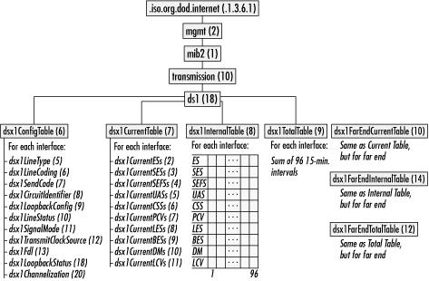
At a high level, the DS1 MIB is simple. Several tables hold configuration and statistical data about each DS1. Performance data is available in three ways: the current 15-minute interval, a data structure containing 15-minute interval data for the past 24 hours, and totals for the past 24 hours. Additionally, data is available from both the near side and the far side. Implementation of the near side is mandatory, while the far-side data must be collected based on the performance reports sent over the facilities data link. Each of these branches will be described in detail, with particular attention paid to useful objects in the branch.
Configuration for each DS1 is held in
the configuration table, ds1.dsx1ConfigTable.
Each row in the configuration table contains configuration
information for one DS1. One of the items in the row is the
DS1’s interface index in the MIB-2 interfaces table. All
objects in this section begin with
ds1.dsx1ConfigTable.dsx1ConfigEntry (18.6.1).
Unless otherwise noted, the data type for these objects is an
enumerated data type defined for that object in the RFC. The objects
are:
-
dsx1LineStatus(integer bit-map, range 1 to 131071) This object contains status information for the line. It returns an integer with information including alarms, failure modes, and loopback status. The bit positions in Figure D-2 are the various statuses that may be reported. Multiple status indications may be returned by adding the appropriate contributions.
-
dsx1SignalMode Using T1 for channelized data transport requires sending signaling information to set up circuits through the telephone network. This object returns the signaling mode in use on an interface. Unchannelized T1 is set to none (1). Channelized T1 is set to robbedBit (2). If the T1 is the underlying physical transport for an ISDN PRI, it is set to
messageOriented(4).
-
dsx1TransmitClockSource This object reports the source of the transmit clock. In most installations it is set to
loopTiming(1), which corresponds to recovering the transmit clock from the received data. Other choices includelocalTiming(2) for a self-generated clock andthroughTiming(3) when the receive clock from another interface on the router is used.
-
dsx1Fdl If the interface does not support use of the facilities data link, this object is set to
dsx1FdlNone(8). Two major standards for using the facilities data link exist: AT&T publication 54016 and ANSI T1.403. These are assigned the values,dsx1Att54016(4) anddsx1AnsiT1403(2), respectively. Thedsx1Fdlobject represents the sum of the capabilities of the device, so it is often set to 6.
-
dsx1LoopbackStatus(integer bit-map, range 1-127) When a loopback mode is activated, this object reports the active loopback types. Like the
dsx1LineStatusobject, this object is a bit map in which the values of the individual bits in Figure D-3 correspond to the various loopback types that can be returned.
Statistics are gathered from each interface at 15-minute intervals. These intervals may, but need not, line up with quarter hours on the wall. The current statistical table holds the numbers being collected in the current 15-minute interval. All entries are Gauge32 counters, which range from 0 to 4,294,967,295.
During a 15-minute window, the current
statistical data is available from the
dsx1CurrentTable. All entries in the table begin
with ds1.dsx1CurrentTable.dsx1CurrentEntry
(18.7.1). Here are the entries:
-
dsx1CurrentSESs This object measures the number of severely errored seconds (SESs) in a 15-minute interval. SESs are 1-second intervals that contain any one of the following errors.
For ESF-framed links:
320 or more path code violations
At least one OOF defect
At least one AIS defect
For SF-framed links:
Framing bit errors
At least one OOF defect
1,544 or more line code violations
Tip
Because unavailability is defined to start at the beginning of a 10-second stretch of SESs SNMP agents must either lag statistical reporting by 10 seconds (to the onset of unavailability) or alter line statistics to reflect a line being declared unavailable.
-
dsx1CurrentDMs Degraded minutes (DMs) are minutes in which the functionality of the line is degraded, but still usable; these correspond to 60-second intervals in which the error rate is estimated to be greater than 10-6 but less than 10-3.
Degraded minutes are calculated only from usable time, which is defined as seconds that are not unavailable seconds or severely errored seconds. Usable seconds are grouped into consecutive 60-second blocks to form minutes. Degraded minutes are 60-second blocks with an estimated error rate exceeding 10-6.
Historical data for the most
recent 24-hour period is maintained in the
dsx1IntervalTable. Figure D-4
shows the logical structure of data in the interval table.
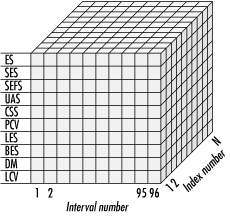
Each DS1 interface is given a unique identifying number, which can be cross-referenced to the MIB-2 interface index number. Time is divided into 15-minute intervals; 96 intervals comprise one 24-hour day. Performance data for the 96 preceding 15-minute intervals is available in the SNMP analog of a three-dimensional array.
At the conclusion of each 15-minute interval, the 96th entry is pushed out of the table, each interval in the table is shifted down one, and the current interval statistics are copied to interval 1.
To make it easier to obtain total
counts for the previous 24-hour period, the DS1 MIB also includes the
dsx1TotalTable. Instead of performing 96 SNMP
queries on the appropriate objects in the interval table and adding,
network managers can consult the appropriate cell in the total table.
Figure D-5 shows how the total table relates to the
data in the interval table.
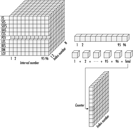
For the purposes of performing the addition, each invalid 15-minute interval is considered to have a zero count. To offer a feel for acceptable numbers in the total table, Table D-2 shows the performance thresholds used by the U.S. Defense Information Systems Agency, the organization that maintains the data network used by the U.S. military and intelligence community, to evaluate circuit performance.
If the line supports it, statistics are also collected for the far end of the DS1. Far-end statistics are gathered from performance reports over the facilities data link. Far-end statistics are not available on SF-framed T1s because they do not support the facilities data link channel. Implementation of far-end tables is optional.