Classic MP requires that all links in a bundle terminate into the same device. Fragments are held in memory and must be conveniently accessible to a single MP process for reassembly. For a circuit-switched path between two endpoints under the control of the same company, it is easy to have one machine on both ends of the link.
Service providers are a different story.[32] No matter how large vendors can make dial-up termination equipment, there will always be a service provider who needs something bigger. Service providers may have several large routers terminating subscriber PPP sessions in a POP. All the T1 circuits providing the dial-up lines are aggregated together into one hunt group. At peak times, the dial-up channel a user receives is likely to be almost random; ISDN subscribers can easily have bearer channels terminated on separate routers.
Two major approaches have been developed to allow MP sessions to terminate correctly into a massive POP. One is to use additional protocols to direct subsequent calls to the access server already terminating the existing MP sessions. Alternatively, access servers can communicate with each other to determine when new sessions have landed on the “wrong” access server. The first chassis to accept an incoming session and instantiate the bundle becomes the bundle head and is responsible for performing bundle-related operations such as fragment reassembly. Layer-two tunneling techniques are used to forward fragments from the “wrong” access server to the bundle head. The bundle head is the logical peer of the dial-in user, even though the routing of MP fragments to that peer takes a somewhat circuitous path. A high-level sketch of the two approaches is shown in Figure B-16.

In the call-steering approach, the first link in the bundle is terminated by one of the many access servers at the POP. Incoming sessions to the main POP phone number, 555-1111, are routed to the first free line into the POP. If a call is terminated by the first access server, it responds with a message to help additional sessions be routed to the terminating server. One method of doing this is to use the Bandwidth Allocation Control Protocol (BACP) to inform the dial-in client of a different number for additional sessions. In Figure B-16, the access server would tell the client to use 555-1112 for any additional sessions.
Multiple chassis can terminate the member link calls when layer-two techniques are used, so the client can use the main POP number for any additional sessions. If additional sessions are split across multiple access servers, the layer-two forwarding of fragments will ensure a seamless MP session. Layer-two techniques are often referred to generically as Multi-Chassis MP (MMP) because sessions may be terminated across several access servers. This is not to imply that MMP is a standardized protocol—in fact, all the major vendors have taken different approaches.
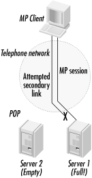
The biggest advantage of the layer-two techniques is that they make better use of the available hardware. When using a call steering technique, the danger is that a call will land on a busy server. When the client tries to establish additional secondary MP links, the busy server will not be able to accept them. However, spare capacity might exist at the POP. This is shown in Figure B-17.
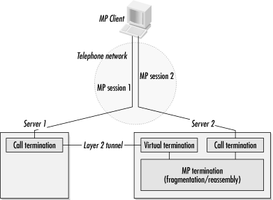
The layer-two techniques separate the MP processing into two distinct parts. Call termination is not special, and any piece of hardware in the POP can perform it. It is only the MP fragmentation and reassembly that must be done centrally at the bundle head; the telephone calls may be received by any of the units in the POP.
In Figure B-18, the first session is terminated on the first access server. MP fragments are passed over an internal bus to the MP termination routines, which run on the first access server’s CPU. When the client places a second call in the MP session, it lands on the second access server. After using discovery protocols to determine where the MP termination point is, the second server opens a layer-two tunnel to the MP termination point. (As an implementation detail, the first server may create a virtual call termination interface to the layer-two tunnel.) All the MP termination functions are performed centrally on the first access server, but it does not need to have the capacity to terminate every call from the POP.
When using a layer-two approach, the devices at the end of a link can handle bandwidth control. Both ends of the link have the same information and can use different algorithms to determine if additional capacity is necessary. To prevent link thrashing—where links are repeatedly established by one end and torn down by the peer—it is recommended that only the system that initiated the link establishment be allowed to remove it.
The major networking vendors each have a proprietary MMP technology. Nortel’s Multilink Multinode Bundle Discovery Protocol is published in RFC 2701 and will be considered in more detail in the next section. Lucent’s Multi-Chassis MP (MCMP), derived from the Ascend MAXStack protocols, is not documented in a detailed form. Cisco’s solution is the Stack Group Bidding Protocol (SGBP). Proprietary approaches can survive in MMP protocols because customers typically try to have homogenous POPs. With only one vendor in the POP, customer demand for an open, interoperable MMP standard is limited.
Of the common techniques, only Nortel’s is specified in the level of detail required for an interoperable implementation. RFC 2701 details the operation of Nortel’s Multilink Multinode PPP Bundle Discovery Protocol. All the proprietary layer-two approaches to MMP are similar, but I will describe Nortel’s in detail because it is documented publicly and interoperable implementations are, in theory, possible.
When a call comes in, LCP establishes the data-link layer and basic MP negotiations. When that is done, there are three possibilities for the call:
It is the first call from that user, and the bundle head should be created.
It is a secondary link for an established bundle, and the bundle head is on the chassis terminating the call. In this case, the new link can simply be added to the existing bundle using standard MP techniques.
It is a secondary link for an established bundle, and the bundle head is on another chassis. In this case, the call-terminating device uses an L2TP to send the MP fragments to the bundle head. The bundle head performs all fragmentation and reassembly.
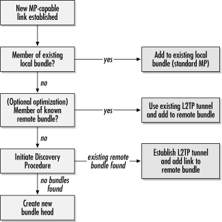
Incoming calls are handled according to the procedure depicted in Figure B-19, as described in the following steps:
The terminating server checks for an existing bundle head on its own chassis. If a bundle head exists, it is case 2 and the new member link is attached to the existing bundle.
As an optimization, a new link for a bundle terminated on a different, but known, chassis can simply be added to the remote bundle using the existing L2TP tunnel. This step is optional.
The location of the bundle head is unknown, so the terminating chassis will use the discovery procedure to attempt to find the bundle head. If discovery finds a remote bundle head, the L2TP tunnel is established and the new member link is attached to the remote bundle head. If discovery fails, it indicates that this is the first link and a bundle head is created.
Bundle-head creation must be a fast process. Power users may attempt to initiate two ISDN B channel connections almost simultaneously, and it is preferable if one of the two stations establishes a bundle head that the other may join. However, if two simultaneous bundle heads are created, an election procedure is used to determine which chassis will terminate the bundle head.
The format of the discovery messages is shown in Figure B-20. The data in a discovery message begins with a 2-byte type code. Queries use a type code of 1, and responses use a type code of 2. A 2-byte length field is set to the length, in bytes, of the endpoint ID field at the end of the message, not including the header. Election procedures make use of the 4-byte random ID, which will be discussed in the next section. To make endpoint ID matching as fast as possible, a 2-byte hash is included in the message. Hashes are a way of speeding up endpoint matching; the calculation method is detailed in the RFC. At the end of the discovery message is a variable-length endpoint ID, which is a concatenation of several MP attributes. Although the fields in the endpoint ID have individual meanings to the MP process, for two incoming calls to be included in the same bundle, the discovery protocol treats them as a string of bits that must match bit-for-bit. In order to ensure that the endpoint ID will result in a bundle match for calls terminated by different access servers, all access servers joined together in a group must have identical EDs.
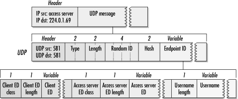
The discovery protocol is a request-response protocol, similar to ARP in its operation. When an incoming call goes all the way to step 3 and the discovery process is initiated, queries are sent out to the IANA-reserved multicast address of 224.0.1.69 on the IANA-allocated UDP port of 581. In the rare cases when multicast facilities are not available, the limited all-ones broadcast address, 255.255.255.255, is used instead. By default, messages are transmitted with a time-to-live (TTL) of 1. To guard against message loss, the discovery protocol retransmits messages if no response is received. The number of messages and the query interval are configurable.
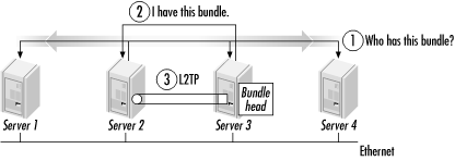
If a query arrives that matches a link that already has a bundle head established, the server with the bundle head responds with a unicast response message. Response messages simply have different type codes. This case is shown in Figure B-21.
Quick responses are important. At crowded POPs, busy access servers may need to search through hundreds of bundles to determine whether the query matches any of the bundles they are currently terminating. Comparing endpoint identifiers can be a slow process involving byte-by-byte comparisons. To speed up the process, the hash is generated and sent along with each query message. When a query is received, the endpoint identifier in the query message need only be compared to the bundles with matching hashes. Hashes do not guarantee a match, but they reduce the number of slow byte-by-byte comparisons servers must perform.
If no response is received after transmitting all the queries, it is assumed that no bundle head exists. Once a server begins creating a bundle head, it will multicast a response message to minimize the number of elections by informing the other servers that it will be responsible for the bundle head.
Robustness is built into the discovery protocol through a retransmission counter, which may range from 1 to 15. By default, three transmissions are used before concluding that there is no bundle head. Lower retransmit counter values increase the probability that a lost packet will result in the creation of multiple bundle heads. Higher values increase the amount of time necessary for the discovery procedure to time out and begin creating a bundle head. No retransmission counter is used for lost reply messages. Instead of retransmitting, missed reply messages are simply triggered by retransmitted queries. In addition to the number of queries, the query interval may be configured. The interval is expressed in tenths of a second and may range from 1 to 15.
When bundle heads are established simultaneously, ties are broken by the random ID field. Each new connection to a server is given a unique identification number. IDs can be reused only when there is no longer a danger that they can be confused with an earlier connection. For this reason, it is recommended that the ID field increase with time. If the random ID field is the same, the tie is broken by the lowest IP address. When the tie is broken, the victor sends two response messages and forms the bundle head. Other servers receive the response message and update their bundle lists with the location of the bundle head.
All MMP solutions take the general shape of the Nortel solution described previously. A method of bundle discovery finds the bundle head, and a layer-two encapsulation method sends fragments from the call termination point to the bundle head.
MCMP is not a documented protocol, but it is similar to the Nortel solution. When a new link is established to a MAX access server, several requests are sent out within one second. These messages are sent as a link layer broadcast (with an IP destination of 255.255.255.255) on port 5151. To avoid overwhelming other devices on the link, an Ethernet multicast address from an Ethernet OUI assigned to Ascend is used (01:c0:7b:0:0:1). When another system owns the bundle, it responds to allow the terminating MAX to join the new call to an existing bundle. If no response is received, the bundle is created locally. The Ascend solution also includes an encapsulation method to ferry MP fragments from the terminating node to the bundle head.
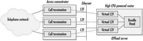
Cisco’s MMP solution is also similar to the Nortel solution. Instead of L2TP, it uses Cisco’s Layer Two Forwarding (L2F) protocol to encapsulate MP fragments. Assignment of the bundle-termination function is based on Cisco’s Stack Group Bidding Protocol (SGBP). Rather than creating bundle heads where they initially land, SGBP allows systems to bid for the right to create them. Bidding means that bundle heads can be distributed relative to CPU power, which allows higher-powered routers to be used for bundle head functions. MP fragmentation and reassembly require higher CPU power than terminating the telephone call. SGBP allows network administrators to design POPs with simple access servers to terminate incoming calls and high-powered routers to terminate MP sessions. When high-powered routers are used only for MP session termination, Cisco refers to them as offload MMP servers. These are illustrated in Figure B-22. Cisco has not published detailed specifications of their MMP solution.
[32] By service provider, I do not mean ISP exclusively. IT departments at large companies are often called on to run massive dial-in setups and function, in effect, as service providers for employees.