
As initially specified, HDLC did not include multiprotocol support or link quality monitoring and was not useful for anything other than frame description. These shortcomings were addressed by Cisco’s extensions to HDLC (cHDLC).[15] cHDLC is an HDLC frame with an Ethernet type code to identify the network protocol carried in the frame. The basic frame structure is shown in Figure 8-6. Framing components are identical to standard HDLC, with the opening and closing flags and FCS.
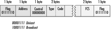
Addressing in cHDLC is simple. The address is either 0x0F for unicast packets or 0x8F for broadcast packets. Labeling a frame as broadcast or multicast has very little significance because IOS does not support multidrop links. Broadcast is simply a reflection of higher-level protocols designating a frame as a broadcast. Control information is set to zero; cHDLC does not support the HDLC window. To distinguish between packets, the third and fourth bytes contain a type code, which is usually the Ethernet type code for the higher-layer protocol. Table 8-2 shows common type-code assignments. After the type code, the higher-level packet is encapsulated as it would be on an Ethernet network. After the data, a frame check sequence and flag close out the frame.
Table 8-2. cHDLC protocol codes
|
Protocol |
cHDLC protocol code (hexadecimal) |
|---|---|
|
IP |
0x0800 |
|
Cisco SLARP (not RARP!) |
0x8035 |
|
EtherTalk |
0x809b |
|
AARP |
0x80f3 |
|
IPX |
0x8137 |
|
DECnet phase IV |
0x6003 |
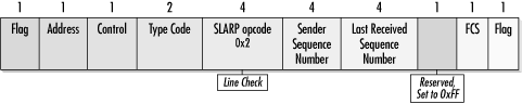
Frames using the Reverse ARP Ethertype are used for Cisco’s Serial Line ARP (SLARP). SLARP is a router-to-router protocol that provides a method of dynamic address assignment as well as link-integrity verification. To distinguish between the two operations, SLARP frames begin with a 4-byte type code. Currently, only three codes are defined. Address requests use a code of zero, and replies use a code of one. Keepalive frames use a code of two.
Address request and response packets are similar in structure; both frames are shown in Figure 8-7. In address request packets, the address and mask fields are zero, and the last two bytes are not defined. Replies include the address and mask of the network. Usually, point-to-point serial links use a 30-bit mask.

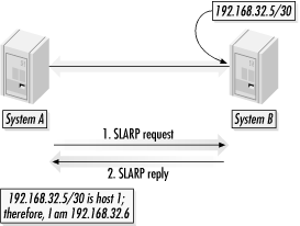
SLARP does not support complex or subtle configurations. It assumes that both ends of the link are on the same IP subnet and that one system is host 1 and the other system is host 2. A logical IP network with a 30-bit subnet mask (255.255.255.252) has four IP numbers. The first IP number has a host field of all zeros and is commonly used to refer to the network itself. The second and third IP numbers are used for two hosts on the network, and the fourth IP number is the all-ones broadcast.
SLARP assumes a 30-bit network and deduces the host number from the advertisement. If SLARP receives a response, and the host number on the logical IP network is 1, the requesting system deduces it is host 2. Conversely, if the response indicates that it is from host 2, the requesting system assumes it is host 1. Figure 8-8 shows a request-response cycle.
To ensure that links with physical layer connectivity can be used for data transport, SLARP includes a basic keepalive mechanism. Both ends of the link send out polling messages and monitor received polls to keep track of the link state. Figure 8-9 shows the basic format of a SLARP keepalive. Following the type code of 2, two 4-byte sequence numbers track line quality, and a 2-byte reliability field is set to all ones.
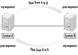
Most link layer protocols rely on a request/response polling mechanism. HDLC incorporates both the request and response into the same frame by including two sequence numbers after the type code. Each direction on a link corresponds with a flow of keepalive frames. Sending stations transmit the outbound sequence number first and attach the latest inbound sequence number. Figure 8-10 shows the operation of the sequence-numbering mechanism. Each direction maintains a sequence number, with mysequence used for the outbound sequence number and yoursequence used for the inbound sequence number.
The cHDLC mechanism allows for the first sequence number to serve as a link layer echo request, with the response coming in subsequent frames on the other side. When a SLARP address request is received, sequence numbers are reset to zero.
Sequence numbers are incremented by one for each keepalive frame that is transmitted. Missed frames or frames corrupted in transit are still transmitted and will still cause the sequence number to rise. Unlike some other sequence-number schemes, the sequence number in cHDLC is a measure of the total number of keepalives transmitted, not just those that are processed successfully. Therefore, the difference between the transmitted sequence number and the received sequence number is a measure of the link quality. In normal operations, the transmitted and received sequence numbers should be identical or differ by only one, with the latter case reflecting one keepalive frame “in flight” between the two endpoints. Severe noise or congestion could result in a skew of the window or two; Cisco’s engineers decided that three missed keepalives probably means that the link is dead and should be reported to higher protocol layers as dead.
Recovering from missed keepalive packets is simple. The only number that matters to keepalive monitoring is the difference between the transmitted and received sequence number. When a keepalive is missed, the difference rises to two. When the next keepalive after the missed transmission is received, the receiver updates the received sequence number. However, the received sequence number is two larger than the previously received one, so the difference is brought back down below the limit.
Cisco HDLC is a snap to configure. Only a few options can be adjusted, and not all options are found on all vendors’ equipment. Here is a list of options:
- Cisco HDLC encapsulation
Cisco IOS defaults to the Cisco HDLC encapsulation on serial links unless otherwise specified. Several vendors default to PPP, but allow HDLC as an option. Cisco’s HDLC encapsulation may or may not be compatible with the HDLC encapsulation offered by other vendors. Refer to the vendor’s documentation for details.
- IP addresses and network mask
If the deployment is compatible with the SLARP addressing model and both ends support the use of automatic address assignment with SLARP, only one end must be configured. However, not all vendors support automatic address assignment with SLARP, and not all deployments can be supported with the SLARP addressing model.
- Keepalive timer
SLARP keepalive packets are sent at regular intervals. IOS defaults to 10 seconds, as do many other implementations.
[15] Some works describe these extensions as “proprietary.” While the Cisco extensions were proprietary in that Cisco developed them, the details were widely distributed and not kept secret. “Proprietary” is often (incorrectly) used interchangeably with “secret” or “single-vendor” in the industry today, and the Cisco HDLC encapsulation does not fit with the connotation.