
Physical layer problems prevent the link layer from coming up. Generally speaking, physical layer problems are easy to spot because red lights will glow on the CSU/DSU until you have fixed them. Figure 11-5 shows the physical layer flowchart.
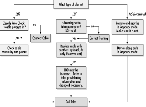
A red alarm indicates a hard down on the T1 span. Either no incoming signal is being received (LOS—loss of signal) or no framing synchronization is possible (LOF—loss of framing). Do not be concerned if the red alarm is not cleared for several seconds after you plug in the cable. CSU/DSUs have a big job to do in sorting through the stream to find the framing bits and lock on to the synchronization pattern. Table 11-1 associates symptoms with possible causes and suggested actions.
Table 11-1. Physical layer diagnostic table
|
Symptom/indication |
Cause |
Corrective action |
|---|---|---|
|
Cable is not connected to telco network |
Plug in the cable. | |
|
Cable is bad |
Test the cable and replace it if necessary. Be sure to include the extended demarc in any testing. Extended demarc cabling should be appropriate for T1 applications. (Category 5 unshielded twisted pair is not!) Occasionally, the transmit and receive pairs may be reversed. | |
|
T1 circuit is bad |
Run a loopback test and call the telco/ISP with the results. | |
|
Wrong frame format is selected |
Check and correct the frame format, if necessary. Most new lines use ESF. | |
|
Wrong line code is selected |
Check and correct the line code, if necessary. Most new lines use B8ZS. | |
|
Cable is bad, so no framing pattern is detected |
T1 uses RJ-48 cabling. Use of straight-through Cat 5 cabling may lead to excessive crosstalk, which may corrupt framing bits. | |
|
Other end is not transmitting correctly |
Check LBO and run loopback tests if the remote end is in yellow alarm. Otherwise, call the ISP/telco. | |
|
CSU/DSU at one end is in loopback mode |
Check to ensure that the CSU/DSUs at the end-user locations are not in loopback mode. Equipment sold to service providers (ISPs) may be able to send loopback commands through the network. Ensure that this option is disabled. | |
|
Device along path is in loopback mode |
If the ends of the line are not in loopback or sending loopback commands, an intermediate device is probably in loopback. The T1 service provider can trace the signal. |
Both RJ-48 and RJ-45 specify an 8-pin modular jack. Regular Cat 5 cabling will fit into an RJ-48 jack without difficulty and may even work for relatively short cabling runs. On longer runs, though, use of Cat 5 UTP (Ethernet) cabling for T1 circuits may cause problems. If possible, avoid cable runs of more than 50 feet between the NIU and the CSU/DSU.
Ethernet uses two pairs: pins 1 and 2 are used to transmit, while pins 3 and 6 are used to receive. Standard Ethernet wiring twists the component wires in a pair together because twisted pairs have lower electromagnetic field emissions and are less susceptible to interference from external fields. RJ-48, the pinout used for T1, uses two different pairs: pins 1 and 2 are used for reception, and pins 4 and 5 are used to transmit.
Some Cat 5 patch cables are wired incorrectly, with twisted pairs formed by pins 1 and 2, pins 3 and 4, pins 5 and 6, and pins 7 and 8. When an incorrectly wired patch cable like this is used for a long NIU-to-CSU run, pins 4 and 5 will be in separate pairs, leaving the transmit pair vulnerable to interference.
Even if the Cat 5 pairs are twisted together correctly, Cat 5 is, by definition, unshielded wiring. T1 pulses may be much smaller than Ethernet pulses by the time they arrive at the CSU/DSU and can be swamped by any noise much more easily. If you observe problems with Cat 5 cabling, replace it with shielded twisted-pair cabling (with the appropriate pairs twisted together, of course).
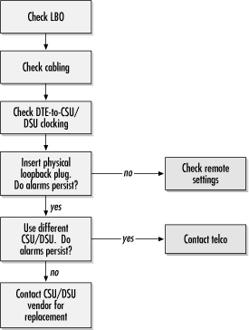
The most significant thing about a yellow alarm is that framing is received correctly, so the remote transmit to local receive path is good. A yellow alarm is sent by the remote end to indicate that it is not receiving a signal. The problem exists somewhere in the local transmit to remote receive path. SF sets the second bit in each channel to zero to indicate RAI, while ESF transmits RAI over the facilities data link. A troubleshooting flowchart is shown in Figure 11-6.
Improper transmissions to the telco network that do not allow the remote end to synchronize framing patterns cause yellow alarms. Two main culprits are LBO and clocking.
LBO ensures that pulses hit the first repeater with the appropriate amplitude. Pulses that are too big or too small will not be processed correctly and might even be reflected at jacks. For smart jacks, LBO should usually be set to 0 dB. If possible, check with the telco technician who installed the line or the documentation retained from the initial line turn-up. When LBO is set incorrectly, pulses may be too small to register or so powerful that they reflect and interfere with successive pulses. One way to determine whether LBO may be a problem is to vary the LBO setting on the CSU/DSU and see if the yellow alarm state changes. If it does, that is a clear indication that LBO needs to be reconfigured.
To make sure the CSU/DSU is functioning correctly, create a loopback plug by taking an RJ-45 plug and linking pin 1 to pin 4 and pin 2 to pin 5. Insert the loopback plug into the telco-side CSU/DSU and adjust the line build out to 0 dB. The CSU/DSU should establish physical connectivity to itself and clear the yellow alarm.
If alarms persist, the DTE-to-CSU/DSU cable may be bad, or the CSU/DSU itself may be bad. If spares are handy, try swapping out the cable and the CSU/DSU in turn to see if the problem is repaired. In a router with integrated CSU/DSU ports, connect the line to a different port and repeat the test. On routers with multiple line cards, select a port on a different line card if possible. If the line comes up with a different CSU/DSU, contact the CSU/DSU vendor for a replacement under any applicable warranties or support agreements.
Yellow alarm causes and corrective actions are summarized in Table 11-2.
Table 11-2. Yellow alarm diagnostic table
|
Symptom/indication |
Cause |
Corrective action |
|---|---|---|
|
Framing received OK, but not transmitted OK |
Bad local cable |
Test cable with cable tester and replace if necessary, or swap cable with a new one |
|
Outbound line errors |
Eliminate crosstalk due to untwisted transmit pair (see previous section on cabling) Line build out is attenuating signal too much; reduce to zero | |
|
LBO setincorrectly |
Verify LBO settings with the telco and adjust accordingly | |
|
CSU/DSU is bad |
Connect to a different CSU/DSU or port on the router and contact vendor for replacement | |
|
Blinking yellow alarm |
Common indicator used to indicate yellow alarm transmission |
Correct problem causing transmission of yellow alarm |
|
False yellow alarm on SF links |
Use 23 or fewer time slots, or switch to ESF |
Three error counters offer most of the insight into further physical difficulties. Controlled slips, seconds in which the physical layer framing is lost, and bipolar violations can be caused by incorrect configuration or crosstalk. In theory, a functioning line on a well-maintained network should have no errors, and any positive error count can indicate a potentially serious condition. To diagnose the underlying problems indicated by rapidly increasing error counts, use the flowchart in Figure 11-7.
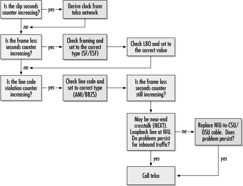
Clock slips occur due to mismatched timing between the two ends of the T1. Timing can drift for a variety of reasons, but links with multiple telcos are especially susceptible to timing problems because the different telcos may employ different primary reference source clocks.
Excessive bipolar violations are the result of one of two problems. An AMI line receiving B8ZS code words will record bipolar violations, and a high bipolar count can indicate that a device that should be set for AMI is instead set for B8ZS. B8ZS devices receiving AMI-encoded data, however, will not generally record line code violations due to excessive zeros.
If the line coding inserts intentional bipolar violations and the local CSU/DSU has an incorrect line code setting, all of the inserted intentional bipolar violations will be flagged. On the other hand, the violations could be caused by a noisy line with crosstalk. After verifying that the line code is set correctly and the cable is good, report the problem to the telco.
Bipolar violations accompanied by clock slips indicate near-end crosstalk, often abbreviated by the acronym NEXT. When cable pairs run close together, the magnetic fields resulting from a strong signal on one pair may induce a current in a nearby pair. Twisting cable pairs tightly both reduces the emissions and improves immunity to crosstalk. Near-end crosstalk is most often seen at the customer end of a T1 because the transmit power is the strongest there, while the received signal is at its weakest point and susceptible to being drowned out by the crosstalk signal. Standards limit the acceptable crosstalk levels at various points on the T1 line, but staying below the limits imposed by the standards may require the use of high-quality prefabricated cabling. Extended demarcs and the attendant wiring problems are the most common cause of near-end crosstalk. Timing-problem troubleshooting is outlined in Table 11-3.
Table 11-3. Troubleshooting timing problems