
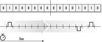
In common encoding schemes, ones are represented by voltage pulses and zeros are represented by the lack of a voltage pulse. Each pulse is approximately 3 volts in amplitude and has a 50% duty cycle, meaning it takes up half of the time slot for pulse transmission. Pulses have a tendency to spread out in the time domain as they travel down a line, as illustrated in Figure 3-1. Restricting the initial transmission to occupy half the time slot helps the repeaters, and the receiving end, find the middle of each time slot and stay synchronized.
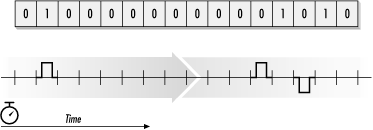
Commonly, a scheme called bipolar return to zero or Alternate Mark Inversion (AMI) is used. One and zero are sometimes referred to as mark and space, respectively, in communications jargon. AMI gets its name from the fact that only ones, or marks, result in pulses on the line. Successive pulses are encoded as positive and negative voltages, as shown in Figure 3-2.
Alternating pulse polarity enables a quick-and-dirty form of error detection. AMI specifies that polarity must alternate, so two successive pulses of the same polarity, such as the sequence in Figure 3-3, might be an error. (Bipolar schemes can catch many errors, but not all of them. Errors in voice transmission result in odd sounds and can be shrugged off. Data transmission is far less forgiving, which is why far better error-detection techniques were developed.)
In a sidebar in Chapter 1, I made a brief reference to synchronous and asynchronous communications. This book is about synchronous communications: both sides of links must agree on when to look for a bit. Long strings of zero bits result in no activity on the wire. If a string of zeros were to persist for a long period of time, the two ends of the link might disagree on its length and be forever out of sync. To prevent two sides from disagreeing on when to look for a pulse, the standards specify a maximum number of successive zeros and a minimum pulse density. Both constraints enable the electronics in the CSU/DSU to lock on to pulses and synchronize their clocks.[9]
The simple-minded solution is to require transmission of pulses at regular intervals to prevent long zero strings—a simple matter of injecting one bits. In the initial schemes, every eighth bit was stolen for timing purposes and transmitted as a one. Only seven data bits were available in every PCM sample slot, which limited effective throughput to 56,000 bits per second. Injected ones were data on the line, even if the data-communications equipment at both ends ignored them; as a result of this background activity, the transmit and receive lights glowed faintly even when no user data was being transferred.
Blindly stuffing a one into the eighth bit time of each sample period restricted transmission to seven bits. When data services were used to transmit ASCII text, throughput did not suffer because ASCII characters are only seven bits. With the evolution of data services beyond text, bit stuffing removed one-eighth of the throughput—a condition that became more and more unacceptable with increasing bandwidth demands.
[9] Requiring synchronization between the two ends is a slight fudge on my part. Strictly speaking, the requirement is that each side maintains a fixed offset relative to the other side’s clock; that is, the two clocks must remain phase locked.