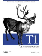
HDLC’s frame format is specified in ISO/IEC 3309 and shown in Figure 8-1. In the figure, the control field is ordered with the most-significant bit first, though when frames are transmitted on the network, the least-significant bits are transmitted first.
Tip
A note on both byte and bit order for this chapter: ISO and ITU diagrams typically show bits in the order they are transmitted on the wire, or least-significant bit first. IETF diagrams, on the other hand, typically display most-significant bits first. Except where noted, this chapter uses the most-significant bit first notation.
HDLC frames open and close with the frame flag (0111 1110; 0x7E). Flags assist devices at either end of the link by bounding frames for error-checking procedures. Idle HDLC links may still be physically active. Two idle states are defined by ISO. Two frames may also share the flag sequence. When sharing the flag between successive frames, the closing flag in the first frame is also treated as the opening flag of the next frame.
After the flag, HDLC transmits an address byte. HDLC was designed to support multidrop links, with one primary station and many secondaries all connected to the same circuit. Stations discard frames addressed to other stations. Use of the address byte depends on the adaptation of HDLC used on the link.
After the address byte, HDLC transmits the control byte. HDLC defines three frame types, each with their own control-byte format, as shown in Figure 8-1. Control information has one or two bits to determine the frame type, a poll/final (P/F) bit, plus sequence numbers and coding information. The poll/final bit is derived from SDLC. Primary stations use it to demand an immediate response from secondaries, and secondaries use it to signal the end of data transmission to the primary.
Following the control data, a variable-length data field contains the upper-layer protocol packet. After the data field is a 2-byte frame check sequence (FCS), which ensures data integrity, and a closing flag to enable HDLC framers to find the end of the frame. To prevent data or the FCS from being confused with the flag, any sequence of more than five ones in the data field is altered by the injection of a zero bit. Receivers discard zero bits that follow five consecutive ones. The later section, Section 8.2.4, further discusses this procedure.
In addition to the 1-byte control and address fields, extensions exist that allow both 2-byte address fields and 2-byte control fields. Extended addressing and control allow for longer sequence numbers, but there is no fundamental difference between the two.
Information frames carry higher-layer protocol packets in the data field. HDLC assigns sequence numbers to frames and can be configured to provide positive acknowledgment. Acknowledgments may be piggybacked on to I-frames or carried in S-frames.
HDLC specifies a window, much like the sliding windows in TCP. HDLC can transmit several frames without an acknowledgment, and acknowledgments can report the reception of multiple I-frames. Not all vendors implement the HDLC window. Cisco’s adaptation of HDLC explicitly does not use the window.
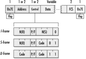
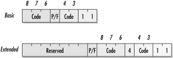
Figure 8-2 compares the basic (1-byte) and extended (2-byte) control information used with I-frames. HDLC implementations recognize I-frames by picking out the zero in the least-significant bit of the control information. Basic control information is also called the mod-8 form because three sequence number bits lead to a sequence space of eight frames. Senders and receivers keep track of the total number of frames and use the remainder, after dividing by eight, as the sequence number on the wire. Likewise, extended control information is often referred to as the mod-128 form for a similar reason.
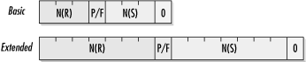
HDLC uses supervisory frames for flow control. Four types of S-frames are defined:
Figure 8-3 shows the use of the S-frame control information in both the basic and extended formats. Like Figure 8-2, it is ordered most-significant byte first and most-significant bit first. HDLC implementations recognize S-frames by setting the first two transmitted bits of control information to 10. The two forms of control information share S-frame codes.
In the extended control information for S-frames, the high-order four bits in the least-significant byte are reserved and set to zero.
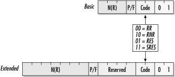
Unnumbered frames are used for link initialization, disconnection, and miscellaneous operations. The U-frame’s common operations include setting the link for ABM using the Set Asynchronous Balanced Mode (SABM) command and transferring supervisory information with the Unnumbered Information (UI) type.
Figure 8-4 shows the basic and extended U-frame formats. Bit positions containing code bits are labeled with the ISO-specified bit position numbers. (The figure, like all others in this section, is shown most-significant byte first and most-significant bit within each byte first.) The five labeled bits are used to create a code.
When U-frames use extended control information, bit 5 in the control information is unspecified, and the high-order seven bits in the most-significant byte are reserved and set to zero. Codes used for U-frames are described in Table 8-1.
The Set...Extended commands are used to select extended (2-byte) control information. On T1 links, the important commands are SABM, which ensures that the routers at both ends of the link are able to send frames, and UI, which is used by HDLC-derived protocols to transfer information.
Table 8-1. U-frame codes
|
Code[a] |
Name |
Command/response[b] |
Description |
|---|---|---|---|
|
00-001 |
SNRM |
C |
Set Normal Response Mode. Designates the receiver as the secondary station in an NRM configuration. |
|
11-000 |
SARM |
C |
Set Asynchronous Response Mode. Designates the receiver as a secondary station, but ARM allows the secondary to transmit without permission. |
|
11-100 |
SABM |
C |
Set Asynchronous Balanced Mode. Sets the link to ABM mode. |
|
00-010 |
DISC |
C |
Disconnect. Places the secondary station into disconnected mode. |
|
11-011 |
SNRME |
C |
Set Normal Response Mode Extended. Same as SNRM, but uses 2-byte control information. |
|
11-010 |
SARME |
C |
Set Asynchronous Response Mode Extended. Same as SARM, but uses 2-byte control information. |
|
11-110 |
SABME |
C |
Set Asynchronous Balanced Mode Extended. Same as SABM, but uses 2-byte control information. |
|
10-000 |
SIM |
C |
Set Initialization Mode. Orders the secondary station to perform initialization procedures. |
|
00-100 |
UP |
C |
Unnumbered Poll. The “reach out and touch someone” frame to see if the receiver is alive. |
|
00-000 |
UI |
C/R |
Unnumbered Information. Used to send information to the secondary station. |
|
11-101 |
XID |
C/R |
Exchange Identification. Sent by the primary station to the secondary to request information about the secondary. |
|
11-001 |
RSET |
C |
Reset. Resets the state information, including sequence numbers, in the receiver. |
|
00-111 |
TEST |
C/R |
Test. TEST frames are echo requests. Receivers respond to a TEST frame with a TEST frame as soon as possible. |
|
11-000 |
DM |
R |
Disconnected Mode. Sent by secondary stations when they are in the nonoperational disconnected mode. |
|
00-110 |
UA |
R |
Unnumbered Acknowledgment. Sent in response to SNRM, SARM, SABM, SNRME, SARME, SABME, RSET, SIM, and DISC commands. |
|
10-001 |
FRMR |
R |
Frame Reject. Sent when a frame is valid, but was received incorrectly. |
|
00-010 |
RD |
R |
Request Disconnect. Sent by the secondary station when it wishes to enter disconnected mode. |
|
10-000 |
RIM |
R |
Request Initialization Mode. Sent by secondary stations to request initialization information from the primary station. |
[a] Codes are displayed in bit order: 34-678. [b] Codes may overlap because HDLC distinguishes between commands and responses. | |||
Early SDLC and HDLC networks often used Non-Return to Zero Inverted (NRZI) line coding. To transmit a zero, NRZI changes the voltage. Ones bits are transmitted by sending the same voltage as in the previous bit time. As a result, long sequences of ones appear as a flat voltage lines with no state changes. Bit times are not readily apparent from the flat line, and the ends of the connection may fall out of synchronization. To avoid losing synchronization, HDLC stuffs in a zero after five consecutive ones between the framing flags. HDLC receivers then monitor for inserted zeros following five ones and remove the stuffed zeros before passing data up to higher layers. Figure 8-5 illustrates this.
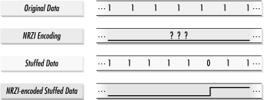
Figure 8-5 shows how HDLC’s bit stuffing helps to maintain synchronized timing. In the original data, a long string of ones is present. When that is encoded with NRZI, it becomes a flat line with no voltage changes, and a timing unit may find it difficult to maintain accurate timing throughout that absence of state changes. On synchronous links, HDLC stuffs in a zero after the first five ones, which leads to the generation of a voltage transition. The bit stuffing rule also guarantees that the flags create a unique pattern for framers to search for—any occurrence of 01111110 in the frame header or data field will be stuffed to 011111010.
ISO 3309 also includes procedures for data transparency on 7-bit links as well as procedures to escape control characters. Transparency allows special control characters such as XON, XOFF, and DELETE to pass through asynchronous links without affecting intermediate communications equipment.