A man is as old as his arteries.
When bringing up a T1, a CSU/DSU is required by FCC part 68 to protect the telco network from your equipment. If the CSU/DSU does not function correctly, whether due to component failure or misconfiguration, the line will not come up. Unfortunately, producing clear, understandable printed documentation has never been a goal of data communications equipment vendors. CSU/DSU manuals have improved to the point of basic intelligibility, but even the best manuals require a solid understanding of telco networking.
In a perfect theoretical world, wires have no resistance and voltage pulses can travel forever. The real world, however, is rarely anything like the world of theory. (There is a reason that physicists joke about spherical frictionless cows, after all.) Repeaters and signal regenerators along T1 spans are the first admission of a practical world. Line build out (LBO) is the second concession to practicality.
Two different types of connections are used on T1 lines. A long-haul connection is made to the telco network. The first repeater may be up to 3,000 feet away from the end-user location. CSUs must be able to drive the pulse up to 3,000 feet, so the arriving pulse at the first repeater is still strong enough to be regenerated. Long-haul line build out is used to avoid problems that arise from having multiple T1 customers in an area. It works by reducing the signal to the level required by the telco network. Short-haul connections are digital cross-connect links up to 655 feet that are made between user-owned devices such as PBXs. Short-haul line build out is also called line equalization. Equalization increases the signal strength above the reference level. For historical reasons, a network interface is abbreviated DS1, and the local side is often labeled DSX or DSX-1. Figure 6-1 contrasts short- and long-haul line build out.

All T1 connections to a telco network must be made with long-haul settings. Two main reasons motivate the use of long-haul LBO. The first relates to T1 repeaters, which are designed to detect incoming pulses at a wide variety of voltages. Some repeaters, however, cannot sense pulses unless they exhibit a loss of at least 7.5 dB from the nominal transmission level. Such repeaters will not register one bits from pulses that are not sufficiently attenuated and will therefore reconstruct a stream of continuous zeros. To work with these older repeaters, some CSU/DSUs may apply a default LBO setting of -7.5 dB.
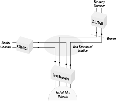
T1 also uses line build out to prevent crosstalk at “non-repeatered line junctions.” In Figure 6-2, two T1 lines run in the same conduit before reaching the first repeater. One customer is farther away, so its signal in the shared conduit is much weaker than the signal from the nearer customer. If crosstalk exists between the two paths when the difference between the signals exceeds 7.5 dB, the resulting noise will disrupt the operation of the repeater and cause errors. To prevent this, T1 uses line build out to make sure that the signals from both customers are at approximately the same level at the route junction. Rather than adding extra cable to the nearby customer’s path, the LBO setting is adjusted on the nearby customer’s CSU/DSU to create signal loss.
Long-haul LBO settings insert a deliberate signal loss into the path. The loss that LBO inserts matches the loss from cabling, so LBO can be used to equalize the virtual path length even though the physical path length is different. Figure 6-3 illustrates this.
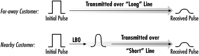
In Figure 6-3, the shorter line uses line build out circuitry to give it the same transmission loss as the longer line. LBO-induced loss must therefore mirror the loss induced by a cable. T1.403 lays out a reasonably complex mathematical transform to accomplish the goal of mimicking cable loss.
End spans in T1 lines typically have smaller loss budgets than the main interoffice sections. Inter-repeater sections may have losses up to 30 dB, but end spans are usually designed for a maximum loss of 16.5 dB, which corresponds to approximately 3,000 feet. Line build out is used to ensure that all signals arriving from customers have approximately the same level. Most customer equipment allows you to select between 0 dB and 22.5 dB loss in steps of 7.5 dB.
The telco supplying the line determines the appropriate LBO setting and includes this with the order. If the LBO setting is not specified, ask the installation technician from the phone company. (The installer won’t want to make a trip back simply to change the LBO.) Most new installations use smart jacks, which generally use a full-strength input signal and thus a 0 dB LBO setting. Some vendors may ship equipment with a default LBO setting of -7.5 dB because there are repeaters that will not detect pulses unless a 7.5 dB attenuation has taken place.
In the beginning, the demarc was the interface between the CSU and the DSU, which was known as a DSX-1. Although the demarc has now shifted to the network side of the CSU, companies continue to build some telephone equipment with a DSX-1 interface. The most common examples of this are phone switches (PBXs). Channel banks and multiplexers may also fall into this category. Connecting equipment with a DSX-1 interface to the telephone network requires a CSU. To simplify the electronics, a pulse received at the DSX-1 interface must have the same characteristics as a pulse transmitted out the CSU network interface.
Cable loss gets in the way of this ideal goal, so equipment that connects to CSUs must provide line equalization, which is sometimes called short-haul line build out. This feature increases the signal level so that it is received at the end of the cable matching the nominal pulse that the CSU transmits. The level is increased, and pulse edges are enhanced so that the cable loss wears them down to a “normal” shape.
Equalization is set in multiples of 133 feet and can range from 0 to 655 feet. Typical settings are 0-133 feet, 134-266 feet, 267-399 feet, 400-533 feet, and 534-655 feet. Naturally, many vendors have implemented different configuration methods.
When using T1 as a transport for external data links, a CSU/DSU is used to connect to the telco network. To connect to the telco network, follow the telco’s rules and configure LBO to the setting that the telco requires. Most new T1 installations place the telco network interface unit (NIU) in the same room as the customer router. Smart jacks can accept a variety of pulse heights, but it is generally advisable to set the LBO to 0 dB. Many CSU/DSUs incorporate automatic LBO settings. A variety of approaches are used to select the correct setting, but a typical one is to monitor the amplitude of received voltage pulses and set the line build out accordingly. T1 uses line equalization (short-haul build out) only when two pieces of customer equipment are being connected. T1 also commonly uses line equalization when connecting a PBX to a CSU.
Table 6-1 lists common line build out settings.
Table 6-1. Common line build out settings
|
Short-haul options |
Long-haul options[a] |
|---|---|
|
0-133 feet (no boost) |
0 dB (no loss) |
|
134-266 feet |
7.5 dB |
|
267-399 feet |
15.0 dB |
|
400-533 feet |
22.5 dB (maximum loss) |
|
534-655 feet (maximum gain) | |
[a] Vendors may use different signs on the long-haul build out. In spite of the confusion, long-haul build out settings always go in increments of 7.5 dB and are always a smaller output signal. | |