
The great artist is the simplifier.
Development of digital-transmission facilities in the 1960s and 1970s made low error rates a notable attribute of the telecommunications landscape in the 1980s and 1990s. Early packet-switching standards, most notably X.25, compensated for high error rates with extensive buffering and retransmission. Not all protocols that were run on X.25 links had reliability features, so providing reliability in the access protocol was a good thing. As the world moved toward protocols designed with the OSI model in mind, however, reliability and retransmission moved to higher layers of the stack. This resulted in duplicated effort and needless delays, especially on relatively clean digital links.
Frame relay was developed in response to the changing environment and, in many circles, was widely viewed as a direct replacement for X.25 networks. Frame relay specifies only the link layer interconnection of networks. Reliability is minimally addressed through the use of a frame check sequence that allows a frame relay network to discard corrupted frames; sequencing, data-representation errors, and flow control are delegated to higher-level protocols. (For the purposes of this book, most of the “higher-level” flow control related functions are delegated to TCP.)
To view frame relay strictly as a link layer takes too narrow a view; taken as a whole, frame relay provides the standards for building a packet-switched WAN. Designing and implementing frame relay networks is far beyond the scope of this book, though, so this chapter looks only at the encapsulation and management features with which frame relay users must be familiar.
Before the development of wide-area packet-switching technologies, connecting geographically distant locations required a choice between several unappealing alternatives. By leasing dedicated capacity from the telephone network, organizations could build “private” networks out of leased lines.[17] Long-haul leased circuits were (and still are) extremely expensive, and beyond the means of all but the richest institutions. (And even they had to make sure the capacity of traffic between sites justified the expense.) Less well-heeled companies contending with financial reality opted for public data networks built on X.25 or for simple dial-up links, with the possibility of ISDN in the relatively modern telecommunications era. The last option was also often quite expensive, and the capacity was limited. No solution existed for an organization that wished to have fast access without a gigantic budget for network connectivity.
Frame relay filled this void.[18] A frame relay service gives its subscribers a virtual connection between two points because the network that moves the data from one point to the other is shared between all subscribers. Like other data packet-based or cell-based data-transmission methods, frame relay is based on the idea of statistical multiplexing: data is often transmitted in bursts, and it is unlikely that any single party will use the entire capacity for an extended period of time.
Frame relay connections come in two flavors. Permanent virtual circuits (PVCs) are “nailed up” and appear to be logically equivalent to a leased-line transmission facility, while switched virtual circuits (SVCs) allow subscribers to “dial” remote sites and maintain connections for only as long as necessary. This book focuses on PVCs because they are more widely used and involve far simpler signaling.
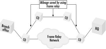
PVCs are priced in a manner less sensitive to distance than leased lines, which makes them popular for long-haul connections. The basic setup is shown in Figure 10-1. To access the frame relay network, a leased line is used to connect to a frame relay switch at the frame relay carrier’s point of presence (POP). Data is then carried by the carrier’s network, often represented (and also referred to) as a cloud, to a remote POP, where a leased access line carries the data to its destination. Customer equipment is referred to as the frame relay DTE, while the carrier equipment is the frame relay DCE. The frame relay DCE is the entry point to the frame relay network. Some network engineers may refer to the frame relay DCE as the frame relay “server.”
Furthermore, frame relay allows multiple virtual connections to use the same physical hardware. A single access link may carry PVCs to several remote locations. To enable the network to distinguish between frames bound for different locations, each outgoing frame is tagged with an address. Frame relay addresses are referred to as data link connection identifiers (DLCIs). Figure 10-2 shows this.
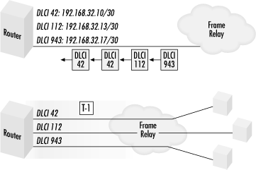
Generally speaking, DLCIs have only local significance. Carriers may reuse DLCI numbers throughout the network. DLCIs need not be the same on both ends of a PVC. DLCI values 0 and 1023 are reserved for signaling, as will be discussed later. DLCI values of 1 through 15 are also reserved. Depending on the carrier’s implementation, DLCI values typically range from 16 to 991 or from 16 to 1007. If a carrier chooses to use the extended 4-byte header, enough DLCI values exist for each PVC in the frame network to have a unique DLCI. For obvious reasons, these are called global DLCIs.
When purchasing frame relay services, there are a variety of options for the committed information rate (CIR).[19] All traffic up to the CIR is given priority treatment, while traffic beyond the CIR is marked as “discard eligible.” During quiet times, subscribers may burst above their CIR. When demand for bandwidth exceeds supply, discard eligible traffic will be discarded. If dropping all discard-eligible traffic does not balance demand and supply, traffic within the CIR may be discarded. Low CIRs are often used to sell off as much of the network’s capacity as possible. One common tactic is to sell PVCs with a CIR of zero, which allows carriers to wring every last dollar out of the network capacity by selling off access during the quiet periods only.
[17] I use the term “private” in quotation marks because the transmission facilities were still owned by the telco and not protected against eavesdropping and tampering.
[18] Indeed, frame relay was initially billed as a “virtual private” network because it provided functionality that was identical to a private leased-line network. It is interesting to note that connecting geographically disparate offices is now often handled by IPSec-based VPNs over the Internet, which is also a wide-area packet-switching technology.
[19] CIR is not specified as a parameter of the link. Instead, a burst size and a burst duration are assigned to the port on the frame relay switch, and the relationship between the two gives the CIR. When users exceed the burst size in the burst time interval, the network begins to throttle back traffic.