In the 1970s, AT&T developed a system of codes for the different types of jacks used at customer premises. These jack codes were called Universal Service Order Codes (USOCs), and jack specifications were known as Registered Jacks (RJs). The USOC lives on in Part 68 of the FCC rules, which has adopted parts of the USOCs and the RJ system.
Common designations are RJ-11, which is a modular telephone jack found on all modems, and RJ-45, which is the jack used by Category 5 UTP Ethernet wiring. Each jack has a number to designate its type, as well as an optional letter. Some of the letters are listed in Table E-3.
Table E-3. Meaning of letters in the USOC
|
Letter |
Meaning |
|---|---|
|
C |
Surface- or flush-mounted jack |
|
W |
Wall-mounted jack |
|
S |
Single-line jack |
|
M |
Multiline jack |
|
X |
Complex jack |
T1s are terminated by RJ-48X jacks, which are complex jacks because they incorporate shorting bars for automatic loopback. The RJ-48 pinout is given in Table E-4.
Table E-4. RJ-48X pinout
|
Pin number |
Usage |
|---|---|
|
1 |
RX ring |
|
2 |
RX tip |
|
3 |
Grounding |
|
4 |
TX ring |
|
5 |
TX tip |
|
6 |
Grounding |
|
7 |
Unused |
|
8 |
Unused |
Pins 3 and 6 are used for grounding by connecting the leads to the metal shields on the cable. Regulatory approval depends on the presence of the shield grounding.
Warning
Regulatory approval requires that the grounding pins be used. Without a properly grounded cable, your installation cannot achieve regulatory approval. Put another way, do not make these cables at home!
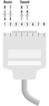
Pins are numbered in Figure E-6. Transmission is based on a tip and ring scheme, so leads in Figure E-6 are labeled with Ts and Rs.
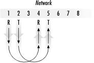
Shorting bars create an automatic loopback, as Figure E-7 shows. When the plug is removed from the jack, pin 1 is connected to pin 4 with a shorting bar, and pin 2 is connected to pin 5. The receive pair from the network is electrically connected to the transmit pair, and any pulses are redirected back to the network. To ensure that any transmitted pulses from the network are reconstituted by the first repeater, the round-trip loss from the last inbound repeater to the jack and back to the first outbound repeater must be within the loss guidelines for a single path between two repeaters. Normally, one path between repeaters is engineered to a 30 dB loss. Half the loss corresponds to 15 dB, which is why end spans may have a maximum loss of only 15 dB.