
6
Data Transfer Group of Instructions
![]() Classification of 8085 instructions
Classification of 8085 instructions
![]() Number of instructions in 8085
Number of instructions in 8085
![]() Instruction type MVI r, d8
Instruction type MVI r, d8
![]() Instruction type MOV r1, r2
Instruction type MOV r1, r2
![]() Instruction type MOV r, M
Instruction type MOV r, M
![]() Instruction type MOV M, r
Instruction type MOV M, r
![]() Instruction type LXI rp, d16
Instruction type LXI rp, d16
![]() Instruction type MVI M, d8
Instruction type MVI M, d8
![]() Instruction type LDA a16
Instruction type LDA a16
![]() Instruction type STA a16
Instruction type STA a16
![]() Instruction type XCHG
Instruction type XCHG
![]() Addressing modes of 8085
Addressing modes of 8085
![]() Register codes
Register codes
![]() Immediate addressing mode
Immediate addressing mode
![]() Register addressing mode
Register addressing mode
![]() Absolute addressing mode
Absolute addressing mode
![]() Register indirect addressing mode
Register indirect addressing mode
![]() Implied addressing mode
Implied addressing mode
![]() Instruction type LDAX rp
Instruction type LDAX rp
![]() Instruction type STAX rp
Instruction type STAX rp
![]() Instruction type LHLD a16
Instruction type LHLD a16
![]() Instruction type SHLD a16
Instruction type SHLD a16
![]() Questions
Questions
In this chapter a total of 13 instruction types covering 83 instructions are explained. In the previous chapter a very simple program to compute the 2's complement of a number was discussed. The program was as follows.
In this program, LDA F840H execution results in movement of information from F840H to Accumulator. Thus it is an example for data transfer group of instructions. CMA execution results in complementing Accumulator contents. It is a logical invert operation. Thus it is an example for logical group of instructions. INR A execution results in incrementing Accumulator contents. It adds 1 to the Accumulator contents. Thus it is an example for arithmetic group of instructions. STA F850H execution results in movement of information from Accumulator to memory location F850H. Thus it is one more example for data transfer group of instructions. HLT execution results in halting the processor. It is an example for machine control group of instructions, as this instruction controls the machine, which is the microcomputer here.
 6.1 CLASSIFICATION OF 8085 INSTRUCTIONS
From the previous discussion, we find that 8085 microprocessor executes a variety of instructions, which can be broadly classified as follows.

Of course, in the earlier simple program, we have not come across some groups of instructions, like the branch group. But, in many programs we frequently come across such instructions. To write a program, we need to first of all know all the instructions that the 8085 can execute.
Towards this objective, in this chapter we describe the data transfer group of instructions, and in the successive few chapters we describe the other groups of instructions.
6.1.1 NUMBER OF INSTRUCTIONS IN 8085
As we have already seen from the previous program, although instruction may be as large as 3 bytes, the opcode is always 1 byte in length. With 8 bits for the opcode, 28 = 256 distinct opcodes are possible. In hexadecimal, the opcodes can be from 00H to FFH. Each opcode corresponds to an instruction. Thus theoretically, 256 instructions are possible in the instruction set of 8085. However, only 246 opcodes are implemented in 8085. They can be discussed under 66 types, which are broadly classified into the six groups listed earlier. Of the 246 opcodes we have:
- – 202 opcodes that are 1-byte long,
- – 18 opcodes that are 2-byte long, and
- – 26 opcodes that are 3-byte long.
In data transfer group, we have 83 opcodes, which will be discussed in this chapter under 13 different types.
6.2 INSTRUCTION TYPE MVI r, d8
MVI is a mnemonic, which stands for ‘MoVe Immediate’. This is an instruction to load a register with an 8-bit value. This instruction uses immediate addressing for specifying the data. We will discuss about addressing modes in a later section. In this type, ‘d8’ stands for any 8-bit data, and ‘r’ stands for any of the following registers.
r = A, B, C, D, E, H, or L
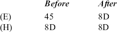
As ‘r’ can have any of the seven values, there are seven opcodes for this type of instruction. It occupies 2 bytes in the memory. MVI E, 8DH is an example instruction of this type. It is a 2-byte instruction, with opcode for MVI E using up one byte, and 8DH using up one more byte. Suppose E register content is 45H. When the 8085 executes this instruction, the contents of E register will change to 8DH. This is shown below in an easy-to-understand manner.
![]()
As summary for the above discussed instruction type, we provide within brackets the size of the instruction, a representative instruction, and the number of opcodes for this type of instruction, as follows.
MVI r, d8 (2 byte; MVI E, 8EH; 7 opcodes)
In fact, from now on, for each instruction this type of summary will be provided.
6.3 INSTRUCTION TYPE MOV r1, r2
MOV is a mnemonic, which stands for ‘MOVe’. This is an instruction to load register r1 with the 8-bit value in register r2. Notice that in 8085 instructions, the first operand specifies the destination, and the second the source. This instruction uses register addressing for specifying the data. In this type, ‘r1’ and ‘r2’ stand for any of the following registers.
r1, r2 = A, B, C, D, E, H, or L
As r1 can have any of the seven values, and r2 can have any of the seven values, there are 7 × 7 = 49 opcodes for this type of instruction. It occupies only 1 byte in memory. MOV E, H is an example instruction of this type. It is a 1-byte instruction. Suppose E register content is 45H, and H register content is 8DH. When the 8085 executes this instruction, the contents of E register will change to 8DH. This is shown as follows.
Notice that H register content is not altered at all. Although Intel has called it a ‘move’ instruction, it is in reality a ‘copy’ instruction.
Another thing to note is that there are instructions like ‘MOV D, D’. This instruction moves contents of D register to D register itself. It is of no use to anybody! However, such useless instructions are also provided in the instruction set of 8085, and some very useful instructions that a programmer looks for are not provided!
Summary: MOV r1, r2 (1 byte; MOV E, H; 49 opcodes)
6.4 INSTRUCTION TYPE MOV r, M
This is an instruction to load register r with the 8-bit value in memory location. But from which memory location? The address of the memory location is understood to be provided in HL register pair. This instruction uses register-indirect addressing for specifying the data.
As r can have any of the seven values, there are seven opcodes for this type of instruction. It occupies only 1 byte in memory. MOV E, M is an example instruction of this type. It is a 1-byte instruction. Suppose E register content is 45H, H register content is F8H, and L register content is 50H. Let us say location F850H has the data value 8DH. When the 8085 executes this instruction, the contents of E register will change to 8DH, as shown below.
Henceforth, for simplicity, only values that have changed will be shown in the ‘After’ column. Thus the simplified diagram for the execution of MOV E, M will be as follows.

Notice that there are instructions like ‘MOV H, M’. This instruction moves contents of a memory location pointed by HL register pair to H register. Generally, it is of no use to anybody! However, such useless instructions are also provided in the instruction set of 8085.
Summary: MOV r, M (1 byte; MOV E, M; 7 opcodes)
6.5 INSTRUCTION TYPE MOV M, r
This is an instruction to load a memory location with the 8-bit value in register ‘r’. But which memory location? The address of the memory location is understood to be provided in HL register pair. This instruction uses register addressing for specifying the data.
As ‘r’ can have any of the seven values, there are seven opcodes for this type of instruction. It occupies only one byte in memory. MOV M, E is an example instruction of this type. It is a 1-byte instruction. The result of execution of this instruction is shown with an example below.

Notice that there are instructions like ‘MOV M, H’. This instruction moves contents of register H to memory location pointed by HL register pair. Generally, it is of no use to anybody! However, such useless instructions are also provided in the instruction set of 8085.
Summary: MOV M, r (1 byte; MOV M, E; 7 opcodes)
6.6 INSTRUCTION TYPE LXI rp, d16
So far we have seen that whenever M is used in an instruction mnemonic, we are referring to the contents of a memory location whose address is given in HL register pair. Thus, if MOV E, M is executed, register E receives contents of memory pointed by HL. Suppose we want E to receive contents of memory location FF00H. Then we have to make sure that HL will have FF00H, before MOV E, M is executed. Thus any instruction involving M, like ‘MOV E, M’, should generally be preceded by instruction/s to load H and L registers with the desired memory address.
How to ensure that HL pair will have the value FF00H? One method is to use the following two instructions: MVI H, FFH and MVI L, 00H.
These two instructions occupy a total of 4bytes in memory. A simpler alternative is to use the 3-byte instruction ‘LXI H, FF00H’, of the type ‘LXI rp, d16’.
LXI is a mnemonic that stands for ‘Load eXtended register Immediate’. Here, a register pair is termed as extended register. It is an instruction that loads register pair ‘rp’ with the 16-bit data denoted as d16. This instruction uses immediate addressing for specifying the data. In this type, ‘rp’ stands for any of the following register pairs.
rp = BC, DE, or HL
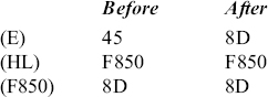
As ‘rp’ can have any of the three values, there are three opcodes for this type of instruction. It occupies 3 bytes in memory. First byte specifies the opcode, and the next two bytes provide the 16-bit data. LXI H, F850H is an example instruction of this type. It is a 3-byte instruction. The result of execution of this instruction is shown below with an example.
![]()
Notice that when specifying the register pair, we specify only the MS register in the instruction mnemonic. The ‘X’ in the mnemonic indicates that it is a register pair, and so if the MS register is specified the register pair is identified. Thus, if our interest is to load HL with F850H, we have to write the instruction as ‘LXI H, F850H’ and not as ‘LXI HL, F850H’ or ‘LXI L, F850H’. LXI H, F850H is stored in memory with F850 stored in byte reversal form as shown below.
- Code for LXI H
- 50
- F8
The other instructions of this type are LXI B, d16 and LXI D, d16.
Summary: LXI rp, d16 (3 bytes; LXI H, F850H; 3 opcodes)
6.7 INSTRUCTION TYPE MVI M, d8
This is an instruction to load a memory location pointed by HL pair with an 8-bit value. This instruction uses immediate addressing for specifying the data. It occupies 2 bytes in memory.
MVI M, 8DH is an example instruction of this type. It is a 2-byte instruction, with opcode for MVI M using up one byte, and 8DH using up one more byte. The result of execution of this instruction is shown below with an example.

Summary: MVI M, d8 (2 bytes; MVI M, 8DH; 1 opcode)
6.8 INSTRUCTION TYPE LDA a16
LDA is a mnemonic that stands for LoaD Accumulator contents from memory. This is an instruction to load Accumulator with the contents of a memory location whose 16-bit address is indicated in the instruction as a16. This instruction uses absolute addressing for specifying the data. It occupies 3bytes in memory. First byte specifies the opcode, and the successive 2bytes provide the 16-bit address.
LDA F850H is an example instruction of this type. It is a 3-byte instruction. The result of execution of this instruction is shown below with an example.

LDA F850H is stored in memory with F850 stored in byte reversal form as shown below.
- Code for LDA
- 50
- F8
There are no instructions in 8085 like LDB a16, LDC a16, etc. As was stated earlier, Accumulator is the most important 8-bit register, whose contents can be loaded in more ways than any other 8-bit register.
Summary: LDA a16 (3 bytes; LDA F850H; 1 opcode)
6.9 INSTRUCTION TYPE STA a16
STA is a mnemonic that stands for STore Accumulator contents in memory. This is an instruction to store accumulator contents in a memory location whose 16-bit address is indicated in the instruction as a16. This instruction uses absolute addressing for specifying the destination. It occupies 3 bytes in memory. First byte specifies the opcode, and the successive 2 bytes provide the 16-bit address.
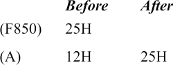
STA F850H is an example instruction of this type. It is a 3-byte instruction. The result of execution of this instruction is shown below with an example.

STA F850H is stored in memory with F850 stored in byte reversal form as shown below.
- Code for STA
- 50
- F8
There are no instructions in 8085 like STB a16, STD a16, etc. As was stated earlier, Accumulator is the most important 8-bit register, whose contents can be stored in memory in more ways than any other 8-bit register.
Summary: STA a16 (3 bytes; STA F850H; 1 opcode)
6.10 INSTRUCTION TYPE XCHG
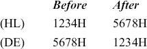
XCHG is a mnemonic, which stands for eXCHanGe. This is an instruction to exchange contents of HL pair with DE pair. This instruction uses implied addressing. It occupies only 1 byte in memory. The result of execution of this instruction is shown below with an example.
Using XCHG instruction, only HL and DE contents can be exchanged. There are no instructions in 8085 to exchange contents of HL and BC or to exchange contents of DE and BC.
Summary: XCHG (1 byte; XCHG; 1 opcode)
6.11 ADDRESSING MODES OF 8085
Shown in the following are the sizes of a few of the instruction types.
| MOV r1, r2 | 1 byte |
| MOV r, M | 1 byte |
| MVI r, d8 | 2 bytes |
Let us see the reason for this before we discuss the addressing modes.

Fig. 6.1 Three-bit register codes for 8085 registers
6.11.1 REGISTER CODES
The 8085 sends out 16-bit address to access one of the 216 = 64K locations. But, for convenience, we indicate memory address using four hexadecimal digits. Similarly, for convenience, we indicate registers as A, B, C, etc. But in reality, the microprocessor has to specify these registers using 0s and 1s only. With only seven registers in 8085, 3 bits are enough to specify a register. The 3-bit register codes for the registers of 8085 are tabulated in Fig. 6.1.
With 3-bit register code, eight registers can be specified. But 8085 has only seven registers. So notice that register code 110 does not specify any register.
Fortunately, the user is not required to memorize these register codes. It is enough if the user realizes that 3bits are needed to specify a register.
Opcode for MOV E, H: Now let us see how Intel has arrived at the opcode for MOV E, H. Six bits are needed to specify the two registers E and H. Still 2bits are left in a byte. These 2bits indicate the code for ‘MOV’. The template chosen by Intel for instruction type MOV r1, r2 is shown in the following. Intel chose 0 1 as the code for MOV.
0 1 r1 code r2 code
From the previous register code table, the opcode for MOV E, H will be
0 1 0 1 1 1 0 0 = 5CH
This can be verified from the opcode chart given in the previous chapter. Similarly, the code for MOV A, B will be: 0 1 1 1 1 0 0 0, which is 78H.
Opcode for MOV E, M: Now let us see how Intel has arrived at the opcode for MOV E, M. How to specify M? Intel solved this problem by choosing 110, which was not used to specify any register, as the code for M. Thus, although M stands for the contents of a memory location pointed by HL, it has 110 as the ‘register code’. Six bits are needed to specify E and M. The remaining 2 bits in the byte indicate the code for ‘MOV’. From the previous register code table, the opcode for MOV E, M will be
0 1 0 1 1 1 1 0 = 5EH
This can be verified from the opcode chart given in the previous chapter. Similarly, the code for MOV A, M will be: 0 1 1 1 1 1 1 0, which is 7EH.
Opcode for MVI E, 34H: Now let us see how Intel has arrived at the opcode for MVI E, 34H. It will be a 2-byte instruction, with 34H as the second byte. In the first byte, 3 bits are needed to specify the registers E. Still = bits are left in the first byte. These = bits indicate the code for ‘MVI’. The template chosen by Intel for instruction type MVI r, d8 is shown as follows.
0 0 r code 1 1 0
From the previous register code table, the opcode for MVI E will be
0 0 0 1 1 1 1 0 = 1EH
This can be verified from the opcode chart given in the previous chapter. Similarly, the code for MVI M will be: 0 0 1 1 0 1 1 0, which is 36H.
Need for addressing modes: A user would like to have the ability to access data in different ways for reasons of convenience. These different ways of accessing data is called the ‘addressing modes’. It is something similar to the way a teacher in a classroom would refer to a particular student in one of the following ways.
- – By mentioning the name of the student;
- – By indicating the position of his seat in the class;
- – By indicating the features of the student, etc.
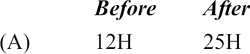
Consider the execution of the following four instructions. In each of these instructions we move 25H to the accumulator, using different addressing modes.
- MVI A, 25H
- MOV A, B

- LDA F850H
- MOV A, M

6.11.2 IMMEDIATE ADDRESSING MODE
In the previous examples, only MVI A, 25H clearly indicates that 25H has to be moved to the A register. This instruction occupies 2 bytes in memory as follows.
- Opcode for MVI A
- 25H
As the data to be moved is immediately after the opcode in the instruction, this kind of addressing is called immediate addressing mode.
6.11.3 REGISTER ADDRESSING MODE
In the previous examples, MOV A, B indicates that contents of the B register have to be moved to the A register. It does not directly say that 25H has to be moved. The instruction only provides the address of the data. In this case, the address is register B, provided in the opcode using 3 bits. This kind of addressing where the data is specified in a register is called Register addressing mode.
6.11.4 ABSOLUTE ADDRESSING MODE
In the previous examples, LDA F850H indicates that contents of the memory location F850H have to be moved to the A register. It does not directly say that 25H has to be moved. The instruction only provides the address of the data. In this case, the memory address is F850H, provided in the instruction using 2 bytes. This kind of addressing where the data is specified in a memory location is called absolute addressing mode. It is called absolute addressing because a full 16-bit memory address is given as part of the instruction, in comparison with register addressing where only a 3-bit register address is provided as part of the instruction.
This type of addressing is sometimes called direct addressing.
6.11.5 REGISTER INDIRECT ADDRESSING MODE
In the previous examples, MOV A, M indicates that contents of the memory location pointed by HL register pair has to be moved to A register. It does not directly say that 25H has to be moved.
If HL content is F850H, we are not moving F850H to Accumulator. We have to take F850H as the memory address, and so move contents of F850H. This is an indirect way of using register pair HL. Hence, this instruction is said to use Register indirect addressing.
6.11.6 IMPLIED ADDRESSING MODE
Consider the instruction XCHG. It exchanges the contents of HL pair with DE pair. But the instruction mnemonic does not explicitly specify that HL and DE are to be exchanged. In other words, we do not write the instruction as ‘XCHG HL, DE’. It is just implied that we have to exchange HL and DE. So this type of addressing is called implied addressing mode. It is also called implicit addressing mode, sometimes.
These are the only addressing modes available in 8085. Some other important addressing modes, like Indexed addressing, are not provided in 8085.
6.12 INSTRUCTION TYPE LDAX rp
LDAX is a mnemonic that stands for LoaD Accumulator from memory pointed by eXtended register denoted as ‘rp’. This instruction uses register indirect addressing for specifying the data. It occupies only 1 byte in memory.
LDAX B is an example instruction of this type. It is a 1-byte instruction. The result of execution of this instruction is shown below with an example.
Only other instruction of this type is LDAX D. Note that LDAX H is not provided in 8085. This is because, LDAX H is the same as MOV A, M in its function.
Also note that there are no instructions in 8085 like LDBX rp, LDCX rp, etc. As was stated earlier, Accumulator is the most important 8-bit register, whose contents can be loaded in more ways than any other 8-bit register.
Summary: LDAX rp (1 byte; LDAX B; 2 opcodes)
6.13 INSTRUCTION TYPE STAX rp
STAX is a mnemonic that stands for STore Accumulator contents in memory pointed by eXtended register denoted as ‘rp’. This instruction uses register indirect addressing for specifying the destination. It occupies only 1 byte in memory.
STAX B is an example instruction of this type. It is a 1-byte instruction. The result of execution of this instruction is shown below with an example.

Only other instruction of this type is STAX D. Note that STAX H is not provided in 8085. This is because, STAX H is the same as MOV M, A in its function.
Also note that there are no instructions in 8085 like STBX rp, STCX rp, etc. As was stated earlier, Accumulator is the most important 8-bit register, whose contents can be stored in memory in more ways than any other 8-bit register.
Summary: STAX rp (1 byte; STAX B; 2 opcodes)
6.14 INSTRUCTION TYPE LHLD a16
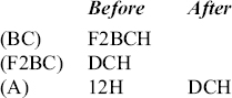
LHLD is a mnemonic that stands for Load HL pair using Direct addressing from memory location whose 16-bit address is denoted as a16. As HL pair has to be loaded, the data comes from two consecutive locations starting at the address a16. This instruction uses absolute addressing for specifying the data. It occupies 3 bytes in memory.
LHLD F2BCH is an example instruction of this type. It is a 3-byte instruction. The result of execution of this instruction is shown below with an example.

LHLD F2BCH is stored in memory with F2BC stored in byte reversal form as shown below.
- Code for LHLD
- BC
- F2
Note that there are no instructions in 8085 like LBCD a16 and LDED a16. As was stated earlier, HL pair is the most important register pair, whose contents can be loaded in more ways than any other register pair.
Summary: LHLD a16 (3 bytes; LHLD F2BCH; 1 opcode)
6.15 INSTRUCTION TYPE SHLD a16
SHLD is a mnemonic, which stands for Store HLpair using Direct addressing in memory location whose 16-bit address is denoted as a16. As HL pair has to be stored, it has to be stored in two consecutive locations starting at the address a16. This instruction uses absolute addressing for specifying the destination. It occupies 3 bytes in memory.
SHLD F2BCH is an example instruction of this type. It is a 3-byte instruction. The result of execution of this instruction is pictorially shown below with an example.
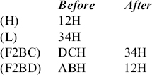
SHLD F2BCH is stored in memory with F2BC stored in byte reversal form as shown below.
- Code for SHLD
- BC
- F2
Note that there are no instructions in 8085 like SBCD a16 and SDED a16. As was stated earlier, HL pair is the most important register pair, whose contents can be stored in memory in more ways than any other register pair.
Summary: SHLD a16 (3 bytes; SHLD F2BCH; 1 opcode)
- Classify the different types of instructions available in 8085, giving an example for each type.
- How many different instructions are implemented in 8085?
- Distinguish between the following pairs of instructions:
- LXI H, 1234H and LHLD 1234H;
- LDA F900H and STA F900H;
- MVI M, 8DH and LXI H, 008DH;
- LHLD FA00H and SHLD FA00H.
- What do you mean by addressing mode? Explain the different types of addressing modes available in 8085, with an example for each.
- Using the register code table, derive opcodes for the following instructions:
i) MOV B, C, ii) MOV M, D, iii) MOV A, M.