
28
Motorola M6800 Microprocessor
![]() Pin description of 6800
Pin description of 6800
![]() Programmer's view of 6800
Programmer's view of 6800
![]() Addressing modes of 6800
Addressing modes of 6800
![]() Immediate addressing
Immediate addressing
![]() Implied or inherent addressing
Implied or inherent addressing
![]() Direct addressing
Direct addressing
![]() Extended addressing
Extended addressing
![]() Indexed addressing
Indexed addressing
![]() Relative addressing
Relative addressing
![]() Instruction set of 6800
Instruction set of 6800
![]() Data transfer group
Data transfer group
![]() Arithmetic group
Arithmetic group
![]() Logical group
Logical group
![]() Branch group
Branch group
![]() Miscellaneous instructions
Miscellaneous instructions
![]() Interrupts of 6800
Interrupts of 6800
![]() Programming examples
Programming examples
![]() Addition of multi-byte numbers
Addition of multi-byte numbers
![]() Exchange of blocks
Exchange of blocks
![]() Block movement without overlap
Block movement without overlap
![]() Questions
Questions
In the previous chapters Intel 8085 and Zilog Z-80 microprocessors were dealt with in depth. In this chapter Motorola M6800, another very popular 8-bit microprocessor will be discussed. This will provide the reader with a comparison of the most popular 8-bit microprocessors.
 28.1 PIN DESCRIPTION OF 6800
Motorola 6800 is another popular 8-bit microprocessor, with which, the following chips are normally used to provide the required functions in a microcomputer.
- —6870 Clock generator;
- —6830 ROM or 68708 EPROM;
- —6810 RAM;
- —6820 Peripheral interface adapter (similar to 8255 PPI in 8085 system);
- —6850 Asynchronous communications interface adapter (similar to 8251 USART);
- —6828 Priotity interrupt controller (similar to 8259 PIC).
The 6800 is available as a 40-pin DIP and its actual pin diagram is shown in Fig. 28.1. The functional pin diagram is shown in Fig. 28.2.


Fig. 28.2 Functional pin diagram of 6800
28.2 PROGRAMMER's VIEW OF 6800
From a programmer's point of view the 6800 is a very simple microprocessor. The programmer's view is indicated in Fig. 28.3a. The simplified internal architecture of 6800 is provided in Fig. 28.3b.
From a programmer's viewpoint the 6800 has:
- Two 8-bit accumulators—A and B;
- Three 16-bit address registers—IX, SP and PC;
- Eight-bit flags register—CCR.
IX register is used as index register. It is shown as X in an instruction mnemonic.
SP is the stack pointer. It is shown as S in an instruction mnemonic.
PC is the program counter.
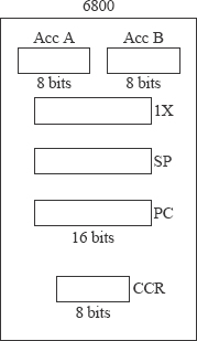
Fig. 28.3a Programmer's view of 6800
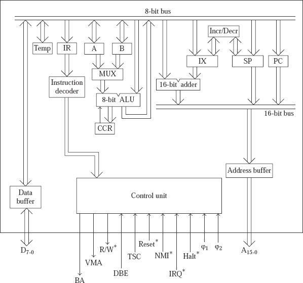
Fig. 28.3b Simplified architecture of 6800
Both A and B registers have almost the same prominence in the instruction set. This was not the case with 8085 where A register was more important than other 8-bit registers. In 6800 there are only a few operations that can be done with A, but not by B. The following list shows the exceptions.
ABA (add B and A, store result in A) is implemented, but not AAB;
SBA (subtract B from A, store result in A) is implemented, but not SAB;
CBA (compare B with A, store result in a temporary register) is implemented, but not CAB;
TAP (transfer from A to CCR) is implemented, but not TBP;
TPA (transfer from CCR to A) is implemented, but not TPB.
Flags register: The flags register in 6800 is termed CCR that stands for condition code register. The flags register contents are indicated in the following. It contains only six flags in the LS position, of which five are status flags and the remaining one is a control flag. The other two bits in the MS bit positions of the CCR are always in the 1 state.
![]()
The status flags are affected based on the result of execution of an instruction. The five status flags are:
H flag: It is half carry flag and is the same as the auxiliary carry of 8085.
N flag: It is negative flag and is the same as the sign flag of 8085.
Z flag: It is zero flag.
Cy flag: It is carry flag.
V flag: It is overflow flag and is described in Z-80.
Note that the P flag of 8085 is omitted here, as it is not a useful flag.
The control flag in CCR is the IM flag. IM stands for interrupt mask. If this flag is set to 1, then IRQ* interrupt will be masked or disabled. It implies that, the 6800 will not be interrupted even if the IRQ* pin is activated by a peripheral. If reset to 0, the IRQ* interrupt will be unmasked or enabled. That is, if the IRQ* pin is activated by a peripheral, the 6800 will be interrupted, provided of course, the higher priority NMI* is not active at the same time.
The IM bit is reset to 0 by the execution of the instruction CLI that stands for CLear Interrupt mask bit. The CLI instruction is functionally the same as the EI instruction of 8085. The IM bit is set to 1 by the execution of the instruction SEI that stands for SEt Interrupt mask bit. The SEI instruction is functionally the same as the DI instruction of 8085. The CCR register is indicated as P in an instruction mnemonic for brevity. For example, the mnemonic TAP stands for transfer from A register to P (CCR) register.
28.3 ADDRESSING MODES OF 6800
There are six addressing modes in 6800. They are:
Immediate addressing;
Implied or inherent addressing;
Direct addressing or page 0 addressing;
Extended addressing or absolute addressing;
Indexed addressing;
Relative addressing.
The following conventions are used in the assembly language programming of 6800.
A value 3FH is indicated as $3F. Thus, $ stands for an hexadecimal number. With $ not indicated, the number is taken to be a decimal number.
Immediate data in an instruction follows ‘#’ symbol. A value that is not preceded by ‘#’ symbol is taken to be a memory address.
If there are two operands for an instruction, the source operand appears first, and the destination operand appears later in the instruction. For example, the mnemonic SBA stands for ‘subtract B from A, and store the result in A’. This is exactly the opposite of the situation in 8085 or Z-80.
The 16-bit data or memory address in a 3-byte instruction is stored in memory with MS byte at a lower memory address, and LS byte at a higher address. It is not stored in byte reversal form that was prevalent in 8085 and Z-80. For example, the instruction STA A $1234 is stored in memory as B7 12 34, where B7 is the opcode for STA A.
28.3.1 IMMEDIATE ADDRESSING
In this addressing, the data to be used in the execution of the instruction is provided in the instruction itself, immediately after the opcode of the instruction. Some examples follow.
| LDA B #$3F; | Load accumulator B with the immediate data 3FH. |
| CPX #$1234; | Compare index register contents with the immediate data 1234H. |
| LDS #$3456; | Load SP with the immediate data 3456H. |
28.3.2 IMPLIED OR INHERENT ADDRESSING
If the operands used in the instruction are within the 6800, the addressing mode is called implied or inherent addressing mode in 6800 terminology. Thus in this addressing mode, the operands will not be in memory. Some examples follow.
| ABA; | Add B and A and store the result in A. |
| ASL B; | Arithmetic shift left B register. |
| CBA; | Compare B contents with A contents. Only flags are affected. |
| CLC; | Clear Cy flag to 0. |
28.3.3 DIRECT ADDRESSING
In this mode the operand will be in memory. This mode is sometimes called page 0 addressing because the operand in memory is restricted to be in the address range of 0000H to 00FFH that happens to be page 0 of memory. Memory in 6800 system can be thought of as made up of pages of size 100H = 256 bytes. Some examples follow.
| ADD B, $25; | Add contents of location 0025H to B register. It is a 2-byte instruction. |
| STA B, $F0; | Store B contents in location 00F0H. It is a 2-byte instruction. |
| LDX $45; | Load IX from contents of locations 45H and 46H. It is a 2-byte instruction. |
Direct addressing is a very powerful addressing mode provided by 6800. This was not present in 8085 or Z-80. Instructions that use direct addressing will be only 2-byte long compared to the 3-byte length of instructions that use extended addressing. As such, direct addressing instruction occupies less space in memory. And more importantly, it takes less time to fetch and execute an instruction that uses direct addressing.
In a 6800 system it is advantageous to have the frequently accessed data stored in the memory range 0000H–00FFH. The data can hence be accessed very fast using direct addressing. To facilitate this, RAM generally starts from location 0000H and grows towards higher addresses in the memory space of 6800. ROM or EPROM is provided the last part of the memory space, and ends with the address FFFFH. This is shown in Fig. 28.4.
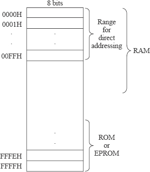
Fig. 28.4 Memory Space In 6800
28.3.4 EXTENDED ADDRESSING
It is the same as the absolute addressing of 8085. However, it is much more powerful here. In this mode the operand will be in memory. The address of the operand is provided after the opcode in the instruction using 16 bits. Because of the 16-bit address, the operand could be anywhere in the memory space in the range 0000H to FFFFH. Some examples follow.
| SBC B $2345; | Subtract from B with carry the contents of location 2345H. Store result in B. |
| CLR $ABCD; | Clear the contents of memory location ABCDH. |
| TST $AABB; | Test contents of location AABBH for 00H value. |
| NEG $6677; | Negate the contents of location 6677H. Contents changed to FEH (=-02) if the original contents of 6677H was 02H. |
| COM $7788; | Complement (1's complement) the contents of location 7788H. Contents changed to FDH if the original contents of 7788H was 02H. |
It may be noted that none of these instructions were present in the absolute addressing mode of 8085. This demonstrates the power of extended addressing in 6800.
If the user writes in assembly language an instruction like COM $0056, the 6800 assembler automatically generates a 2-byte instruction code treating the instruction as COM $56 in direct addressing mode. As such, the practical addressing range for extended addressing could be indicated as 0100H to FFFFH.
28.3.5 INDEXED ADDRESSING
In this mode the operand will be in memory. A part of the address is provided in the IX register and the other part of size 8 bits is provided directly in the instruction. The sum of these two parts provides the complete memory address for the operand. This mode is already described in Z-80. However, in 6800 there is a single IX register compared to the two present in Z-80. Some examples follow. In these instructions, the IX content is assumed to be 1234H.
| ADC B $10, X; | Add with carry to B register the contents of memory location 1244H. |
| STS $30, X; | Store SP contents in memory locations 1264H and 1265H. |
| BIT B $25, X; | AND contents of B register with contents of memory location 1259H. Contents of B remain unchanged. Only flags are affected. |
| CPX $20, X; | Compare IX contents with contents of memory locations 1254H and 1255H. |
28.3.6 RELATIVE ADDRESSING
The relative addressing mode is used in the branch group of instructions. The branch group of instructions that use relative addressing will be only 2-byte long and will be executed faster compared to those that use extended addressing. In relative addressing, a signed 8-bit number will follow the opcode byte. This number indicates whether the branch is to a forward location or to a backward location. The range for branching is 127 locations forward or 128 locations backward from the next instruction. This mode is already described in Z-80. Some examples follow.
| BRA $F0; | Branch unconditionally 10H locations backward (F0H = -10H) from the next instruction after BRA $F0. |
| BEQ $F0; | Branch if equal to zero (Z flag = 1) 10H locations backward (F0H = -10H) from the next instruction after BEQ $F0. |
| BVS $20; | Branch if V flag is set to 20H locations forward from the next instruction after BVS $20. |
| BSR $20; | Branch to subroutine that is 20H locations forward from the next instruction after BSR $20. |
28.4 INSTRUCTION SET OF 6800
Some statistics about the instruction set of 6800 are shown in the following.
- Instruction types: 72;
- Number of opcodes: 197;
- Instruction length: 1, 2, or 3 bytes.
| Instruction length (bytes) | Number Of opcodes |
| 1 | 51 |
| 2 | 103 |
| 3 | 43 |
| Total 197 Opcodes |
Although 6800 has only 197 opcodes compared to the 246 of 8085, it is more powerful than 8085. Its branch group of instructions are more powerful than even Z-80 with about 700 opcodes. The instruction set of 6800 is easy to master considering its simplicity. The power of 6800 instruction set will be demonstrated by some programming examples later. The instructions of 6800 could be classified under the following groups.

The following convention is used in the description of the instruction set of 6800.
d8 = 8-bit data;
a8 = 8-bit address;
a16 = 16-bit address;
IX+a8 = Indexed addressing using IX and 8-bit displacement;
r8 = 8-bit relative (signed) displacement.
LDA/STA = Load/store accumulator;
LDS/STS = Load/store stack pointer;
LDX/STX = Load/store IX register;
TAP = Transfer from A to P;
PSH/PUL = Push/pull (pop).
28.4.1 DATA TRANSFER GROUP
There are 38 opcodes in this group under 14 instruction types.
28.4.2 ARITHMETIC GROUP
There are 55 opcodes in this group under 15 instruction types.
28.4.3 LOGICAL GROUP
There are 73 opcodes in this group under 14 instruction types.
 28.4.4 BRANCH GROUP
There are 23 opcodes in this group under 21 instruction types. The conditional branch instructions of even Z-80 performed branch based on the value of a single flag, except V flag. For example, ‘JR NC, r8’ of Z-80 performed a branch only if Cy flag were 0. In 6800, conditional branch instructions that test V flag are also provided. They are very useful when working with signed numbers and are shown as follows:
BVS—branch if V flag is set
BVC—branch if V flag is cleared.
In addition, there are conditional branch instructions that test more than one flag also in 6800. Such instructions are useful in the comparison of two unsigned or two signed numbers.
In 6800 terminology, ‘higher’ and ‘lower’ are used when comparing unsigned numbers. ‘Greater than’ and ‘less than’ are used when comparing signed numbers. Consider the numbers 85H and 45H as an example. 85H is a negative number (as the MS bit is 1) and 45H is a positive number (as the MS bit is 0) when interpreted as signed numbers. Thus, all the following statements are perfectly true in 6800 terminology.
BHI (branch if higher) and BLS (branch if lower or same) are used with unsigned numbers. BHI and BLS are generally used after a compare operation like ‘CMP B, #$25’. These instructions perform a branch based on the value of Cy flag and Z flag.
BGT (branch if greater than), BGE (branch if greater or equal), BLT (branch if less than) and BLE (branch if less than or equal) are used with signed numbers. They are generally used after a compare operation like ‘CMP B, #$25’. These instructions perform a branch based on the value of sign flag, V flag, and Z flag.
The other instructions under the branch group are:
BRA—unconditional relative branch
JMP—unconditional branch using extended or indexed addressing
BSR—unconditional relative branch to subroutine
JSR—unconditional branch to subroutine using extended or indexed addressing
RTS—return from subroutine
RTI (return from ISS) and SWI (software interrupt) will be described later.
Note that there are no conditional branches to a subroutine and conditional returns from a subroutine. They are not implemented, as it is possible to manage without such instructions. If it is required to branch to subroutine at symbolic memory location SUBR only if Cy flag is 0, it is managed as follows.
BCS NEXT
BSR SUBR
NEXT: next instruction
If it is required to return from subroutine only if V flag is 0, it is managed as follows.
BVS SKIP
RTS
SKIP: next instruction

28.4.5 MISCELLANEOUS INSTRUCTIONS
There are eight opcodes in this group under eight instruction types.
WAI (wait for interrupt) is functionally the same as the HLT instruction of 8085. There are instructions to clear or set the Cy, IM, and V flags. CLC stands for clear carry, SEC stands for set carry and so on.
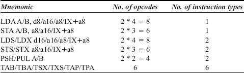
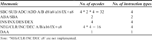
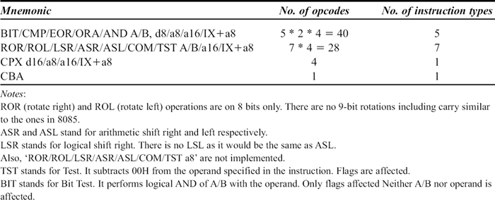
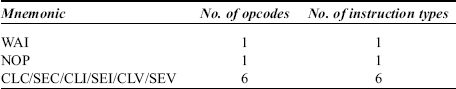
6800 instruction set summary
| Mnemonic | No. Of opcodes |
| BIT/CMP/EOR/ORA/AND/SBC/SUB/ADC/ADD/LDA A/B, d8/a8/a16/IX+a8 | 10 * 2 * 4 = 80 |
| CPX/LDS/LDX d16/a8/a16/IX+a8 3 * 4 = 12 | STAA/B a8/a16/IX+a8 2 * 3 = 6 |
| STS/STX a8/a16/IX+a8 | 2 * 3 = 6 |
| ROL/ROR/LSR/ASR/ASL/COM/TST/NEG/CLR/INC/DEC A/B/a16/Ix+a8 | 11* 4 = 44 |
| PSH/PUL A/B | 2 * 2 = 4 |
| TAB/TBA/TSX/TXS/TAP/TPA | 6 |
| INS/INX/DES/DEX | 4 |
| CBA/ABA/SBA | 3 |
| CLC/SEC/CLI/SEI/CLV/SEV | 6 |
| BCC/BCS/BEQ/BNE/BMI/BPL/BVC/BVS r8 | 8 |
| BHI/BLS/BGT/BGE/BLT/BLE r8 | 6 |
| BRA/BSR r8 | 2 |
| JMP/JSR a16/IX+a8 | 2 * 2 = 4 |
| RTS/RTI | 2 |
| SWI/WAI/NOP/DAA | 4 |
| Note: ‘ROL/ROR/LSR/ASR/ASL/COM/TST/NEG/CLR/INC/DEC a8’ and CAB/AAB/SAB/TBP/TPB instructions are not implemented. | |
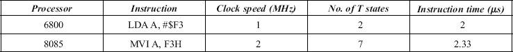
Speed of instruction execution: The typical clock frequency used in 6800 is 1 MHz. The one used in 8085 is 3 MHz. This gives a wrong impression that 8085 is three times faster than 6800. A simple example is provided to prove it to be a wrong impression.
Consider the execution of the 6800 instruction ‘LDA A, #$F3’. Its equivalent in 8085 is ‘MVI A, F3H’. In 8085 this instruction takes a total of seven clock cycles for the opcode fetch, decode and execute portion. It works out to 2.33μs if the 8085 is operating at 3 MHz. In 6800 this instruction takes a total of two clock cycles only—one for fetching and decoding, and the other for execution. It works out to 2 μs if the 6800 is operating at 1MHz. Thus 6800 working at 1 MHz is slightly faster than 8085 processor working at 3MHz.
28.5 INTERRUPTS OF 6800
There are two hardware interrupt pins in 6800 which are NMI* and IRQ*. These are active low interrupt input pins of which NMI* is non maskable. Thus the 6800 gets interrupted whenever the NMI* pin is activated. IRQ* is maskable. It is masked or disabled if the IM flag of CCR register is set to 1 using the SEI instruction. It is also automatically masked whenever the 6800 enters an ISS. In such a case, the 6800 is not interrupted even if the IRQ* pin is activated.
IRQ* is unmasked or enabled if the IM flag of CCR register is reset to 0 using the CLI instruction. In such a case, whenever the IRQ* pin is activated, the 6800 is interrupted, provided NMI* is not active at the same time. This is because, NMI* has a higher priority over IRQ*. When NMI* pin is activated half way through an instruction, the action performed by 6800 is as follows:
The instruction under execution is completed.
PC value saved on the stack.
All the other registers saved on the stack in a particular order as shown in figure 28.5.
IM flag is set to 1.
Jumps to the ISS whose address is provided in locations FFFCH and FFFDH.
If the contents of locations FFFCH and FFFDH are 56H and 78H as shown in Fig. 28.5, then the NMI* ISS starts from 5678H and ends with RTI instruction. The execution of this instruction results in the following.
IM flag is restored to the value that was present prior to interruption.
Register values restored from the stack.
Return to main program by restoring PC value.

Fig. 28.5 Interrupt vectors of 6800 and saving of registers on the stack
As there is no explicit need for saving and restoring registers in the ISS, the interrupt response is much faster than in 8085. In the ISS of 8085, the user had to explicitly save and restore the registers in the ISS, thereby slowing down the interrupt response.
When IRQ* pin is activated half way through an instruction, the action performed by 6800 is very much similar to the activation of NMI*. In this case the 6800 jumps to the ISS whose address is provided in locations FFF8H and FFF9H. If the contents of locations FFF8H and FFF9H are 9AH and BCH as shown in Fig. 28.5, then the IRQ* ISS starts from 9ABCH and the ISS ends with RTI instruction.
In addition to the two hardware interrupts, there is also an SWI (software interrupt) in 6800. This instruction has the mnemonic SWI. When this instruction is executed by the 6800 in a program, the action taken is as follows.
PC value saved on the stack.
All the other registers saved on the stack in a particular order as shown in figure 28.5.
IM flag is set to 1.
Jumps to the ISS whose address is provided in locations FFFAH and FFFBH.
If the contents of locations FFFAH and FFFBH are 22H and 33H as shown in Fig. 28.5, then the ISS for SWI instruction starts from 2233H and it ends with RTI instruction.
The activation of Reset* pin also interrupts the working of 6800. The 6800 always responds to activation of Reset* signal in the following way.
The instruction under execution is immediately suspended.
IM flag is set to 1.
Jumps to the address that is provided in locations FFFEH and FFFFH.
If the contents of locations FFFEH and FFFFH are E0H and 00H as shown in Fig. 28.5, then the jump takes place to E000H. At this location the system initialization program begins.
PROGRAMMING EXAMPLES
28.6.1 ADDITION OF MULTI-BYTE NUMBERS
Write a 6800 assembly language program to add two multi-byte numbers. The size in bytes of the two multi-byte numbers is provided in location 8910H. The first multi-byte number starts from location 8920H with the LS byte and the second one from location 8940H with the LS byte. The result is to be stored from location 8970H starting with the LS byte. For the result, one extra location is provided to account for the carry generated.
A typical input and the expected output are indicated in Fig. 28.6.
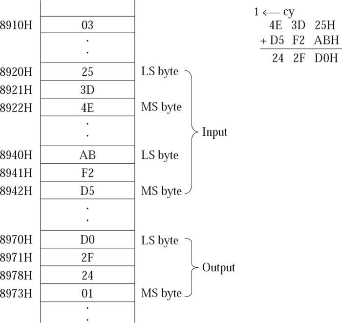
Fig. 28.6 Addition of two multi-byte numbers
Program
CLC
                         LDX #$8920
AGAIN: LDA A $0, X
       ADC A $20, X
       STA A $50, X!

       INX
       DEC $8910
       BNE AGAIN

       CLR $50, X
       BCC EXIT
       INC $50, X
EXIT: WAI
The reader is urged to compare this program with the one in Section 14.2 that used 8085 processor. A shortage of registers was felt while using 8085 processor. The number of registers in 6800 is much less than in 8085. In spite of this, in the above program, register B of 6800 is still available for use. This is because, the usage of indexed addressing in 6800 has resulted in a more compact program, which amply demonstrates the power of indexed addressing mode.
28.6.2 EXCHANGE OF BLOCKS
Write a 6800 assembly language program to exchange contents of two blocks in memory. The number of elements in the block is provided in location 8910H. The two blocks start at locations 8920H and 8940H, respectively.
Typical memory contents before and after program execution are indicated in Fig. 28.7.
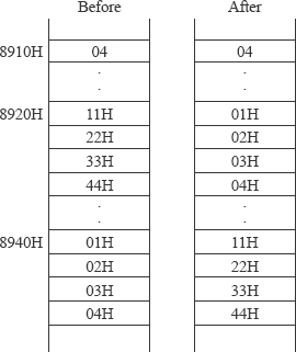
Program
LDX #$8920
                REPEAT: LDA A 0, X
                         LDA B $20, X

                         STA A $20, X
                         STA B 0, X

                         INX
                         DEC $8910
                         BNE REPEAT

                         WAI
The reader is urged to compare this program with the one in Sect. 14.1 that used 8085 processor. The usage of indexed addressing in 6800 has resulted in a more compact program, which once again demonstrates the power of indexed addressing mode.
28.6.3 BLOCK MOVEMENT WITHOUT OVERLAP
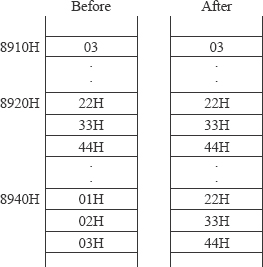
Write a 6800 assembly language program to perform block movement. The blocks are assumed to be non overlapping. The block starting at location 8920H is to be moved to the block starting at location 8940H. The block size is provided in location 8910H.
Typical memory contents before and after program execution are indicated in Fig. 28.8.
Program
LDX #$8920
                AGAIN:   LDA A 0, X
                         STA A $20, X

                         INX
                         DEC $8910
                         BNE AGAI
                         WAI
The reader is urged to compare this program with the one in Sect. 14.4 that used 8085 processor. Once again, the use of indexed addressing in 6800 has resulted in a more compact program.
- With a neat functional pin diagram, explain the pins of 6800.
- With a neat diagram describe the programmer's view of 6800.
- Explain the flags available in 6800.
- Write a note on the addressing modes of 6800 with an example for each addressing mode.
- List the various instruction types available in the data transfer group of instructions.
- List the various instruction types available in the arithmetic group of instructions.
- List the various instruction types available in the logical group of instructions.
- Write a note on the branch group of instructions.
- Comment on the speed of execution of instructions in 6800 and 8085.
- Write a note on the interrupts of 6800.
- Describe the internal architecture of 6800 with a neat diagram.