
10
Branch Group of Instructions
![]() More details about program execution
More details about program execution
![]() PC—Program counter
PC—Program counter
![]() IR—Instruction register
IR—Instruction register
![]() W and Z registers
W and Z registers
![]() Unconditional jump instructions
Unconditional jump instructions
![]() JMP a16—Unconditional direct jump
JMP a16—Unconditional direct jump
![]() PCHL—Unconditional indirect jump
PCHL—Unconditional indirect jump
![]() Conditional jump instructions
Conditional jump instructions
![]() JNC a16—jump if not Carry
JNC a16—jump if not Carry
![]() JC—jump if carry
JC—jump if carry
![]() JNZ—jump if not zero result
JNZ—jump if not zero result
![]() JZ a16—jump if zero result
JZ a16—jump if zero result
![]() JPO a16—jump if parity odd
JPO a16—jump if parity odd
![]() JPE a16—jump if parity even
JPE a16—jump if parity even
![]() JP a16—jump if positive
JP a16—jump if positive
![]() JM a16—jump if minus
JM a16—jump if minus
![]() Unconditional call and return instructions
Unconditional call and return instructions
![]() Difference between call and jump instructions
Difference between call and jump instructions
![]() Conditional call instructions
Conditional call instructions
![]() CNC a16—call if no carry
CNC a16—call if no carry
![]() CC a16—call if carry
CC a16—call if carry
![]() CNZ a16—call if not zero result
CNZ a16—call if not zero result
![]() CZ a16—call if zero result
CZ a16—call if zero result
![]() CPO a16—call if parity odd
CPO a16—call if parity odd
![]() CPE a16—call if parity even
CPE a16—call if parity even
![]() CP a16—call if positive
CP a16—call if positive
![]() CM a16—call if minus
CM a16—call if minus
![]() Conditional return instructions
Conditional return instructions
![]() RNC—return if not carry
RNC—return if not carry
![]() RNZ—return if not zero result
RNZ—return if not zero result
![]() RZ—return if zero result
RZ—return if zero result
![]() RPO—return if parity odd
RPO—return if parity odd
![]() RPE—return if parity even
RPE—return if parity even
![]() RP—return if positive
RP—return if positive
![]() RM—return if minus
RM—return if minus
![]() RSTn—restart instructions
RSTn—restart instructions
![]() Questions
Questions
A total of eight instruction types covering 36 instructions will be explained in this chapter.
The first part of the chapter gives more details about program execution. Various instruction types, such as the conditional and unconditional jump instructions, unconditional and conditional call and return instructions are dealt with in the remaining part of the chapter.
 10.1 MORE DETAILS ABOUT PROGRAM EXECUTION
The way 8085 executes a simple program (without ‘jump’ instructions) is as follows. It fetches the first instruction from memory and executes it. Then it fetches the next instruction from memory and executes it. It continues this way till the halt instruction is fetched and executed.
For example, to compute the 2's complement of the number at location F840H and store the result in location F850H, the program shown in Fig. 10.1 has to be executed.

Fig. 10.1 Assembly language program to compute 2's complement
Let us say, the machine language program is stored starting from memory location F820H as shown in Fig. 10.2.

Fig. 10.2 Machine language program to compute 2's complement
To execute the program, 8085 will have to send out the address F820H and fetch the opcode 3AH for the first instruction ‘LDA F840H’ from memory for execution. In such a case, from which register in 8085 the address value F820H is sent out? The address is sent out from a special purpose register called program counter (PC for short).
10.1.1 PC–PROGRAM COUNTER
PC is a 16-bit register. It contains a memory address. Suppose the PC contents are F820H, then it means that the 8085 Desires to fetch the instruction byte at F820H. After fetching the byte at F820H, the PC is automatically incremented by 1. This way 8085 becomes ready to fetch the next byte of the instruction (in case instruction fetch is incomplete), or fetch the next opcode (in case instruction fetch is over).
In the previous program example, first of all PC is loaded with the value F820H. This is done by typing the ‘Go’ key, then typing ‘F820’, and finally typing the ‘Exec’ key. Then the 8085 performs the following action. It sends out F820H the address, which is the content of the PC. From location F820H it receives 3AH, the opcode for LDA. It is received in an 8-bit register called instruction register (IR for short), as shown in Fig. 10.3.

Fig. 10.3 Table indicating instruction fetch process
10.1.2 IR–INSTRUCTION REGISTER
IR is a special purpose register, which is used to receive the 8-bit opcode portion of an instruction. It is not accessible to the programmer. What it means is that there are no instructions by which the programmer can load it with values of his choice. For example, instructions like ‘MOV IR, D’ or ‘MVI IR, 45H’ are not present in the instruction set of 8085. Thus, IR register is not shown in the programmer's view of 8085.
10.1.3 W AND Z REGISTERS
After the opcode is fetched from location F820H, the PC is incremented to F821H and is sent out as address. Then 8085 receives 40H, the LS byte of data address F840H. It is received in an 8-bit register called Z register. Z is a register, which is used to receive the LS byte portion of the 16-bit address in a 3-byte instruction. It is not accessible to the programmer. Thus, Z register is not shown in the programmer's view of 8085.
Next, PC is incremented to F822H and it receives F8H, the MS byte of data address F840H. It is received in an 8-bit register called W register. W is a register that is used to receive the MS byte portion of a 16-bit address in an instruction. It is not accessible to the programmer.
Now PC is incremented to F823H, but the next instruction fetch does not start as yet. This is because, so far, 8085 has only completely fetched the instruction code for LDA F840H, but it has not yet executed it!
The 8085 executes the instruction LDA F840H, by sending out the address F840H from W and Z registers, and loading the accumulator with the contents of memory location F840H.
Only after the 8085 executes ‘LDA F840H’ instruction, it sends out the address F823H, which is the content of PC, and receives 2FH, the opcode for CMA. It is received in the IR register. Meanwhile the PC is incremented to F824H. As the complete instruction is received by the 8085, it then executes it using the ALU for the complement operation.
Only after CMA instruction is executed by the 8085, it sends out the address F824H, which is the content of PC, and receives 3CH, the opcode for INR A. It is received in the IR register. Meanwhile the PC is incremented to F825H. As the complete instruction is received by the 8085, it then executes it using the ALU for the increment operation.
Only after INR A instruction is executed by the 8085, it sends out the address F825H, which is the content of PC, and receives 32H, the opcode for STA. It is received in the IR register. Meanwhile the PC is incremented to F826H.
Then F826H from PC is sent out as address and 8085 receives 50H, the LS byte of address F850H. It is received in Z register. Meanwhile PC is incremented to F827H. Then F827H from PC is sent out as address and 8085 receives F8H, the MS byte of address F850H. It is received in W register. Meanwhile PC is incremented to F828H. But the next instruction fetch at F828H does not start as yet. This is because, so far the 8085 has only completely fetched the instruction code for STA F850H, but it has not yet executed it! The 8085 executes the instruction STA F850H, by sending out the address F850H from W and Z registers, and storing the accumulator contents in memory location F850H.
Only after STA F850H instruction is executed by the 8085, it sends out the address F828H, which is the content of PC, and receives 76H, the opcode for HLT. It is received in the IR register. Meanwhile the PC is incremented to F829H. As the complete instruction is received by the 8085, it then executes it, which results in halting the processor.
The role of PC in 8085 for simple programs (without jump instructions) can be summarized as follows:
PC is a 16-bit register. It contains a memory address. Suppose the PC contents are F820H, then it means that the 8085 desires to fetch and execute the instruction starting at F820H. After fetching the instruction starting at F820H, the PC is automatically incremented by 1, 2, or 3 depending on the instruction length. Then the instruction is executed, during which the PC value is not changed.
This way PC will be pointing to the next instruction by the time the current instruction is executed.
10.2 UNCONDITIONAL JUMP INSTRUCTIONS
In simple programs there is a linear program flow from the first instruction to the last instruction in the program. But the real power of a computer exists in its ability to change program flow, and the programs should be written to take advantage of this ability.
Change in program flow is needed when a sequence of instructions is to be executed repeatedly. It is also needed when it is required to choose between two or more sequences of actions based on some conditions. The branch group of instructions in 8085 effects such a change in program flow. The branch instructions can be used for effecting a forward branch or a backward branch.
An important subgroup of the branch group of instructions is the jump instructions. The jump instructions are classified into:
- – Unconditional jump instructions, and
- – Conditional JuMP instructions.
10.2.1 JMP A16—UNCONDITIONAL DIRECT JUMP
JMP is a mnemonic that stands for ‘JuMP’ and ‘a16’ stands for any 16-bit address. This instruction is used to jump to the address a16 provided in the instruction. ‘JMP F950H’ is an example instruction of this type. It is a 3-byte instruction. The result of execution of this instruction is shown below with an example.

In the previous example, after 8085 fetches ‘JMP F950H’ the PC value would have been automatically incremented by 3 to F823H. Functionally, JMP F950H can be treated as:
JMP F950H = LXI PC, F950H
Thus, execution of JMP F950H results in loading of PC with the value F950H, overwriting the earlier value of F823H. Hence, after execution of JMP F950H, the instruction MOV C, B at memory location F950H will be fetched and executed. In this example, a forward jump was effected. JMP F805H instruction at location F820H, effects a backward jump.
In the instruction set of 8085, ‘JMP’ is used instead of ‘LXI PC’, because JMP very explicitly indicates a change in program flow. But, LXI PC just indicates that PC value is changed, but its implied change in program flow may go unnoticed by the programmer.
The result of execution of ‘JMP F950H’ can be indicated in terms of change in PC value as follows.
![]()
Summary: JMP a16 (3 bytes; JMP F950H; 1 opcode)
10.2.2 PCHL–UNCONDITIONAL INDIRECT JUMP
PCHL is a mnemonic, which stands for ‘Load PC with contents of HL’. This instruction is used to jump to the address provided in HL register pair. Thus it is an unconditional indirect jump instruction. Because of its indirect jump feature, it is not very commonly used.
It is a 1-byte instruction compared with the direct jump instruction, which is 3-bytes long. Because of this size advantage, it can be useful for jumping to a frequently used portion of the program.
The result of execution of this instruction is shown below with an example.
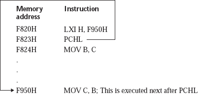
In the previous example, after 8085 fetches ‘PCHL’ the PC value would have been automatically incremented by 1 to F824H.
But execution of PCHL results in loading of PC with the value F950H, which is the content of HL, overwriting the earlier value of F824H. Hence, after execution of PCHL, the instruction ‘MOV C, B’ at memory location F950H will be fetched and executed.
The result of execution of ‘PCHL’ can be indicated in terms of change in PC value as follows.

Summaryi: PCHL (1 byte; PCHL; 1 opcode)
10.3 CONDITIONAL JUMP INSTRUCTIONS
The conditional jump instructions of 8085 perform a jump based on the value of a single flag. The jump takes place based on the value of carry flag, zero flag, parity flag, or sign flag. There is no jump instruction based on the value of auxiliary flag. This is because, generally no one is interested in performing a jump based on this flag!
10.3.1 JNC a16–JUMP IF NOT CARRY
JNC is a mnemonic, which stands for ‘Jump if Not Carry’, and n‘a16’ stands for any 16-bit address. This instruction is used to jump to the address a16 provided in the instruction, only if carry flag value is 0. If carry flag value is 1, program flow continues sequentially. ‘JNC F950H’ is an example instruction of this type. It is a 3-byte instruction. The result ofexecution of this instruction is shown below with an example.
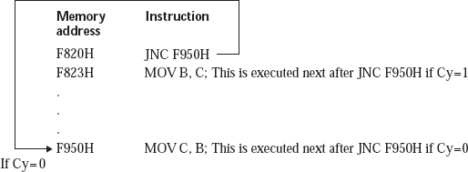
In the previous example, after 8085 fetches ‘JNC F950H’ the PC value would have been automatically incremented by 3 to F823H. But JNC F950H instruction execution results in loading of PC with the value F950H, only if Cy flag value is 0.
Hence, after execution of JNC F950H, the instruction ‘MOV C, B’ at memory location F950H will be fetched and executed only if Cy flag value is 0. If Cy flag value is 1, the PC value will remain as F823H, and so the instruction ‘MOV B, C’ will be executed.
Summary: JNC a16 (3 bytes; JNC F950H; 1 opcode)
10.3.2 JC a16—JUMP IF CARRY
JC is a mnemonic, which stands for ‘Jump if Carry’. This instruction is used to jump to the address a16 provided in the instruction, only if carry flag value is 1. If carry flag value is 0, program flow continues sequentially.
‘JC F950H’ is an example instruction of this type. It is a 3-byte instruction. The result of execution of this instruction is shown below with an example.

Summary: JC a16 (3 bytes; JC F950H; 1 opcode)
10.3.3 JNZ a16–JUMP IF NOT ZERO RSESULT
JNZ is a mnemonic, which stands for ‘Jump if Not Zero result’. This instruction is used to jump to the address a16 provided in the instruction, only if result is not zero, indicated by Z flag value of 0. If Z flag value is 1, program flow continues sequentially. ‘JNZ F950H’ is an example instruction of this type. It is a 3-byte instruction. The result of execution of this instruction is shown below with an example.

Summary: JNZ a16 (3 bytes; JNZ F950H; 1 opcode)
10.3.4 JZ a16–JUMP IF ZERO RESULT
JZ is a mnemonic, which stands for ‘Jump if Zero result’. This instruction is used to jump to the address a16 provided in the instruction, only if result is zero, indicated by Z flag value of 1. If Z flag value is 0, program flow continues sequentially. ‘JZ F950H’ is an example instruction of this type. It is a 3-byte instruction. The result of execution of this instruction is shown below with an example.

Summary: JZ a16 (3 bytes; JZ F950H; 1 opcode)
10.3.5 JPO a16–JUMP IF PARITY ODD
JPO is a mnemonic, which stands for ‘Jump if Parity Odd’. This instruction is used to jump to the address a16 provided in the instruction, only if parity flag value is 0. If parity flag value is 1, program flow -continues sequentially. ‘JPO F950H’ is an example instruction of this type. It is a 3-byte instruction.
Summary: JPO a16 (3 bytes; JPO F950H; 1 opcode)
10.3.6 JPE a16–JUMP IF PARITY EVEN
JPE is a mnemonic, which stands for ‘Jump if Parity Even’. This instruction is used to jump to the address a16 provided in the instruction, only if parity flag value is 1. If parity flag value is 0, program flow continues sequentially.
Summary: JPE a16 (3 bytes; JPE F950H; 1 opcode)
10.3.7 JP a16–JUMP IF POSITIVE
JP is a mnemonic, which stands for ‘Jump if Positive’. This instruction is used to jump to the address a16 provided in the instruction, only if sign flag value is 0. If sign flag value is 1, program flow continues sequentially.
Summary: JP a16 (3 bytes; JP F950H; 1 opcode)
10.3.8 JM a16–JUMP IF MINUS
JM is a mnemonic, which stands for ‘Jump if Minus’. This instruction is used to jump to the address a16 provided in the instruction, only if sign flag value is 1. If sign flag value is 0, program flow continues sequentially.
Summary: JM a16 (3 bytes; JM F950H; 1 opcode)
10.4 UNCONDITIONAL CALL AND RETURN INSTRUCTIONS
Very often a particular sequence of instructions have to be used at several points in the program. Writing the same sequence of instructions at these various points can be avoided by writing this series of instructions as a subprogram. Such subprograms are also variously termed as subroutines, or procedures.
Whenever the instructions in a subroutine are required to be executed, we branch to the subroutine using the CALL instruction. It is a 3-byte instruction, with 1 byte for the opcode, and 2 bytes for the address of subroutine. CALL stands for ‘call a subroutine’. After executing the instructions in the -subroutine we return to the next instruction after the truction in the main program. This is achieved by the execution of the RET (stands for RETurn from subroutine) instruction in the subroutine. RET is a1-byte instruction.
10.4.1 DIFFERENCE BETWEEN CALL AND JUMP INSTRUCTIONS
The difference between a JMP instruction and a CALL instruction is as follows. If a JMP instruction is executed, we jump to the destination location, and the execution carries on from there, without bothering to come back later to the instruction after the JMP.
If a CALL instruction is executed, we jump to the subroutine, and the execution carries on from there till the RET instruction is executed in the subroutine, and then we come back to the instruction after the CALL in the main program.
The address of the next instruction after the CALL instruction is called the return address. This is the address to which the program flow returns when the RET instruction is executed by the 8085. By the time the 8085 fetches the call instruction, the PC would have been incremented by 3, and will be pointing to the next instruction after call. In other words, PC will have the return address by the time the call instruction is fetched.
In order to facilitate such a return, the CALL instruction will first of all store above the top of stack, the return address. Only then the branch to the subroutine takes place.
Thus a CALL instruction can be visualized as push PC value on the stack, and then branch to the subroutine. Thus CALL F900H can be treated as:
CALL F900H = PUSH PC + JMP F900H
Note that there is no direct instruction like PUSH PC in 8085. As part of the execution of CALL instruction, PUSH PC operation is performed.
The RET instruction, which is at the end of a subroutine, loads the PC with the return address popped out from the top of the stack, so that a branch back to the calling program at the next instruction after CALL is achieved. Thus RET can be treated as:
RET = POP PC
In the instruction set of 8085, ‘RET’ is used instead of ‘POP PC’, because RET very explicitly indicates a return back to the calling program. But, POP PC just indicates that PC value is changed, but its implied return to the calling program may go unnoticed by the programmer.
The use of CALL F950H to branch to the subroutine at F950H, and the RET instruction in the subroutine to get back to the main program are illustrated in Fig. 10.4.

Fig. 10.4 Usage of CALL and RET instructions
The way stack contents get affected due to execution of ‘CALL F950H’ is shown below.

Note that if the CALL instruction is at location F820H, the return address stored on the top of the stack is F823H.
Summary: CALL a16 (3 bytes; CALL F950H; 1 opcode)
The way in which the stack contents get affected due to execution of RET is shown below.

Summary: RET (1 byte; RET; 1 opcode)
Using this approach, we can branch any number of times to the subroutine, which is written only once. This saves a lot of memory space for the complete program.
Also usage of subroutines helps in modular design for solving a programming problem. It makes the main program look very simple and compact.
10.5 CONDITIONAL CALL INSTRUCTIONS
The conditional call instructions of 8085 branch to a subroutine based on the value of a single flag. The branch takes place based on the value of Cy flag, Z flag, P flag, or S flag. There is no call instruction based on the value of auxiliary flag. This is because, generally no one is interested in branching to a subroutine based on this flag! The conditional call instructions are 3 bytes in length, 1 byte for the opcode, and another 2 bytes for the subroutine address.
10.5.1 CNC a16—CALL IF NOT CARRY
CNC is a mnemonic, which stands for ‘Call if Not Carry’. This instruction is used to branch to the subroutine whose 16-bit address is provided in the instruction, only if Cy flag value is 0. If Cy flag value is 1, program flow continues in the main program sequentially. ‘CNC F950H’ is an example instruction of this type. It is a 3-byte instruction. The result of execution of this instruction is shown below with an example.

In the previous example, after 8085 fetches ‘CNC F950H’ the PC value would have been automatically incremented by 3 to F823H. But CNC F950H instruction execution results in saving PC value on the stack and loading of PC with the value F950H, only if Cy flag value is 0.
Hence, after execution of CNC F950H, branch to subroutine at memory location F950H will take place only if Cy flag value is 0. After executing the RET instruction in the subroutine, the program flow will continue with the instruction at F823H in the main program.
If Cy flag value is 1, the PC value will remain as F823H, and so the program flow continues with the instruction MOV B, C in the main program.
Summary: CNC a16 (3 bytes; CNC F950H; 1 opcode)
10.5.2 CC a16—CALL IF CARRY
CC is a mnemonic, which stands for ‘Call if Carry’. This instruction is used to branch to the subroutine whose 16-bit address is provided in the instruction, only if Cy flag value is 1. If Cy flag value is 0, program flow continues in the main program sequentially.
Summary: CC a16 (3 bytes; CC F950H; 1 opcode)
10.5.3 CNZ a16—CALL IF NOT ZERO RESULT
CNZ is a mnemonic, which stands for ‘Call if Not Zero result’. This instruction is used to branch to the subroutine whose 16-bit address is provided in the instruction, only if result is not zero, indicated by Z flag value of 0. If Z flag value is 1, program flow continues in the main program sequentially.
Summary: CNZ a16 (3 bytes; CNZ F950H; 1 opcode)
10.5.4 CZ a16—CALL IF ZERO RESULT
CZ is a mnemonic, which stands for ‘Call if Zero result’. This instruction is used to branch to the subroutine whose 16-bit address is provided in the instruction, only if result is zero, indicated by Z flag value of 1. If Z flag value is 0, program flow continues in the main program sequentially.
Summary: CZ a16 (3 bytes; CZ F950H; 1 opcode)
10.5.5 CPO a16—CALL IF PARITY ODD
CPO is a mnemonic, which stands for ‘Call if Parity Odd’. This instruction is used to branch to the subroutine whose 16-bit address is provided in the instruction, only if P flag value is 0. If P flag value is 1, program flow continues in the main program sequentially.
Summary: CPO a16 (3 bytes; CPO F950H; 1 opcode)
10.5.6 CPE a16—CALL IF PARITY EVEN
CPE is a mnemonic, which stands for ‘Call if Parity Even’. This instruction is used to branch to the subroutine whose 16-bit address is provided in the instruction, only if P flag value is 1. If P flag value is 0, program flow continues in the main program sequentially.
Summary: CPE a16 (3 bytes; CPE F950H; 1 opcode)
10.5.7 CP a16—CALL IF POSITIVE
CP is a mnemonic, which stands for ‘Call if Positive’. This instruction is used to branch to the subroutine whose 16-bit address is provided in the instruction, only if S flag value is 0. If S flag value is 1, program flow continues in the main program sequentially.
Summary: CP a16 (3 bytes; CP F950H; 1 opcode)
10.5.8 CM a16—CALL IF MINUS
CM is a mnemonic, which stands for ‘Call if Minus’. This instruction is used to branch to the subroutine whose 16-bit address is provided in the instruction, only if S flag value is 1. If S flag value is 0, program flow continues in the main program sequentially.
Summary: CM a16 (3 bytes; CM F950H; 1 opcode)
10.6 CONDITIONAL RETURN INSTRUCTIONS
The conditional return instructions of 8085 effect a return to the main program based on the value of a single flag. The return takes place based on the value of Cy flag, Z flag, P flag, or S flag. There is no return instruction based on the value of AC flag. This is because, generally no one is interested in returning to the main program based on this flag! The conditional return instructions are 1byte in length.
10.6.1 RNC—RETURN IF NOT CARRY
RNC is a mnemonic, which stands for ‘Return if Not Carry’. This instruction is used to return to the main program, only if Cy flag value is 0. If Cy flag value is 1, program flow continues in the subroutine sequentially. It is a 1-byte instruction. The result of execution of this instruction is shown below with an example.
In the previous example, when 8085 executes CALL F950H instruction, it saves PC value of F823H on the top of the stack, and branches to the subroutine at F950H.
In the subroutine, after 8085 fetches ‘RNC’ the PC value would have been automatically incremented by 1 to F961H. But RNC instruction execution results in loading PC value with the return address from the stack top, only if Cy flag value is 0.
Hence, after execution of RNC, return to the main program at memory location F823H will take place only if Cy flag value is 0.
If Cy flag value is 1, the PC value will remain as F961H, and so the program flow continues with the instruction MOV D, E in the subroutine. Finally when the 8085 executes the RET instruction in the subroutine, return to the main program at location F823H takes place.
Summary: RNC (1 byte; RNC; 1 opcode)
10.6.2 RC—RETURN IF CARRY
RC is a mnemonic, which stands for ‘Return if Carry’. This instruction is used to return to the main program, only if Cy flag value is 1. If Cy flag value is 0, program flow continues in the subroutine sequentially.
Summary: RC (1 byte; RC; 1 opcode)
10.6.3 RNZ—RETURN IF NOT ZERO RESULT
RNZ is a mnemonic, which stands for ‘Return if Not Zero result’. This instruction is used to return to the main program, only if result is not zero, indicated by Z flag value of 0. If Z flag value is 1, program flow continues in the subroutine sequentially.
Summary: RNZ (1 byte; RNZ; 1 opcode)
10.6.4 RZ—RETURN IF ZERO RESULT
RZ is a mnemonic, which stands for ‘Return if Zero result’. This instruction is used to return to the main program, only if result is 0, indicated by Z flag value of 1. If Z flag value is 0, program flow continues in the subroutine sequentially.
Summary: RZ (1 byte; RZ; 1 opcode)
10.6.5 RPO—RETURN IF PARITY ODD
RPO is a mnemonic, which stands for ‘Return if Parity is Odd’. This instruction is used to return to the main program, only if P flag value is 0. If P flag value is 1, program flow continues in the subroutine sequentially.
Summary: RPO (1 byte; RPO; 1 opcode)
10.6.6 RPE—RETURN IF PARITY EVEN
RPE is a mnemonic, which stands for ‘Return if Parity is Even’. This instruction is used to return to the main program, only if P flag value is 1. If P flag value is 0, program flow continues in the subroutine sequentially.
Summary: RPE (1byte; RPE; 1 opcode)
10.6.7 RP—RETURN IF POSITIVE
RP is a mnemonic, which stands for ‘Return if Positive’. This instruction is used to return to the main program, only if S flag value is 0. If S flag value is 1, program flow continues in the subroutine sequentially.
Summary: RP (1byte; RP; 1 opcode)
10.6.8 RM—RETURN IF MINUS
RM is a mnemonic, which stands for ‘Return if Minus’. This instruction is used to return to the main program, only if S flag value is 1. If S flag value is 0, program flow continues in the subroutine sequentially.
Summary: RM (1byte; RM; 1 opcode)
10.7 RSTn—RESTART INSTRUCTIONS
In this case n has a value from 0 to 7 only. Thus the eight possible RST instructions are RST 0, RST 1, …, RST 7. These are basically single-byte call instructions. Functionally RST n instruction is:
RST n = CALL n*8
For example, RST 2 is functionally equivalent to CALL 2*8 5 CALL 0010H. The advantage of RST 2 is that it is only 1 byte, whereas CALL 0010H is 3-byte long. Thus RST instructions are useful for branching to frequently used subroutines.
The reader may wonder how RST n is only 1-byte long, whereas MVI B, d8 is 2-byte long. The reason is that n value is restricted to the range 0-7. So only 3 bits are needed to denote n value, and the other 5 bits in the byte provide the code for RST.
RST 2 is an example instruction of this type. It is a 1-byte instruction. It is functionally same as CALL 0010H = PUSH PC + JMP 0010H. It causes a branch to subroutine at 0010H. Similarly, RST 3 causes a branch to subroutine at 3*8 = 0018H. Thus, the subroutine, which starts at location 0010H should not go beyond memory location 0017H. So at the most only eight locations are available for the subroutine, which is too small in general. This limitation is overcome by branching to a subroutine at some other memory location, like F950H. It is achieved by the combination of RST 2 instruction, and JMP F950H instruction at memory location 0010H, as shown in Fig. 10.5.
The way in which the stack contents get affected due to execution of RST 2 is shown below.

Fig. 10.5 Use of RST 2 to branch to subroutine at F950H
The way in which the stack contents get affected due to execution of RST 2 is shown below.

Note that if the RST 2 instruction is at location F820H, the return address stored on the top of the stack is F821H. Thus PC value is stored on the top of the stack, and a branch to 0010H takes place. But then, because of the JMP F950H at location 0010H, branch to subroutine at F950H finally takes place.
Many times, an I/O port supplies an RST instruction to 8085, when the 8085 is interrupted on INTR pin. Interrupts are discussed in a later chapter.
‘RST’ stands for ‘restart’. They are called restart instructions because, generally one of these instructions is going to transfer control to the monitor program in the microprocessor kit. When a microprocessor kit is switched off, and then switched on, the control is transferred to the monitor program. Thus the action performed by an RST instruction is similar to restarting the kit, and hence the name ‘restart’ instruction. On the ALS-SDA-85M kit RST 1 instruction transfers control to the monitor program.
Summary: RST n (1 byte; RST 5; 8 opcodes)
The complete role of PC in 8085 can be summarized as follows:
PC is a 16-bit register. It contains a memory address. Suppose the PC contents are F820H. Then it means that the 8085 desires to fetch and execute the instruction starting at F820H. After fetching the instruction starting at F820H, the PC is automatically incremented by 1, 2, or 3 depending on the instruction length. Then the instruction is executed, during which the PC value is not changed, if the instruction did not belong to the branch group. This way PC will be pointing to the next instruction by the time the current instruction is executed.
If the instruction belonged to the branch group the following actions take place.
- If the current instruction is an unconditional direct jump or call instruction, PC is loaded with the value provided in the JMP or CALL instruction. Thus, a jump is effected.
- If the current instruction is PCHL, PC is loaded with the value present in HL register pair. Thus, a jump is effected.
- If the current instruction is an RST n instruction, PC is loaded with the value n*8. Thus, a jump is effected.
- If the current instruction is a conditional jump or call instruction, then
- PC is loaded with the value provided in the conditional jump or call instruction, if the condition is satisfied. Thus, a jump is effected.
- PC value is not altered if the condition is not satisfied. In such a case, there will not be a jump.
- Explain the role of Program Counter.
- What is the purpose of Instruction register?
- What is the function of W and Z registers?
- Describe the two types of unconditional jump instructions.
- List the conditional jump instructions of 8085, and explain any one instruction.
- What are subroutines? How are they useful?
- Describe the working of the instructions CALL and RET.
- Compare JMP and CALL instructions.
- List the conditional call instructions of 8085, and explain any one instruction.
- List the conditional return instructions of 8085, and explain any one instruction.
- Explain the working of RST instructions and their use.
- Distinguish between the following pairs of instructions:
- RST 5 and CALL 0028H;
- JMP F090H and CALL F090H;
- SPHL and PCHL;
- RET and RPO;
- CALL F090H and CM F090H.
- RST 5 is 1-byte long, and MVI B, 25H is 2-bytes long. Justify with reason.
- It is desired to branch to subroutine at location F960H using RST 4 instruction. Explain how you achieve it.
- Write a 8085 assembly language program, which takes the 8-bit data from memory location X, and counts the number of 1s and 0s in this byte, and stores the result in memory locations X+1 and X+2, respectively.
- Write a 8085 assembly language program, which performs the addition of two 8-bit signed numbers at locations X and X+1 respectively. If the answer is correct, store it in memory location X+2. If the answer is wrong, store it in location Y.
- (Note: Addition of 40H and 50H gives the wrong answer 90H. It is a wrong answer because 40H and 50H are positive, while 90H is negative.)
- Write a 8085 assembly language program to generate all Fibonacci numbers, which can be represented using 8 bits, and store them in successive locations starting from location X.