
16
Aditional Assembly Language Programs
![]() Search for a number using linear search
Search for a number using linear search
![]() Program to perform linear search
Program to perform linear search
![]() Find the smallest number
Find the smallest number
![]() Program to find the smallest number
Program to find the smallest number
![]() Compute the HCF of two 8-bit numbers
Compute the HCF of two 8-bit numbers
![]() Program to find the HCF of two given bytes
Program to find the HCF of two given bytes
![]() Check for two out of five code
Check for two out of five code
![]() Program to check for two out of five code
Program to check for two out of five code
![]() Convert ASCII to binary
Convert ASCII to binary
![]() Program to convert ASCII to binary
Program to convert ASCII to binary
![]() Convert binary to ASCII
Convert binary to ASCII
![]() Program to convert two-digit hex to two ASCII values
Program to convert two-digit hex to two ASCII values
![]() Convert BCD to binary
Convert BCD to binary
![]() Program to convert a two-digit BCD to binary—method 1
Program to convert a two-digit BCD to binary—method 1
![]() Program to convert a two-digit BCD to binary—method 2
Program to convert a two-digit BCD to binary—method 2
![]() Convert binary to BCD
Convert binary to BCD
![]() Program to convert an 8-bit binary to BCD—method 1
Program to convert an 8-bit binary to BCD—method 1
![]() Program to convert an 8-bit binary to BCD—method 2
Program to convert an 8-bit binary to BCD—method 2
![]() Program to convert an 8-bit binary to BCD—method 3
Program to convert an 8-bit binary to BCD—method 3
![]() Check for palindrome
Check for palindrome
![]() Program to check for palindrome
Program to check for palindrome
![]() Compute the LCM of two 8-bit numbers
Compute the LCM of two 8-bit numbers
![]() Program to compute LCM
Program to compute LCM
![]() Sort numbers using bubble sort
Sort numbers using bubble sort
![]() Program to perform sorting using bubble sort
Program to perform sorting using bubble sort
![]() Sort numbers using selection sort
Sort numbers using selection sort
![]() Program to perform sorting using selection sort
Program to perform sorting using selection sort
![]() Program to simulate decimal up counter
Program to simulate decimal up counter
![]() Generation of time delay
Generation of time delay
![]() Simulate decimal down counter
Simulate decimal down counter
![]() Program to simulate decimal down counter
Program to simulate decimal down counter
![]() Display alternately 00 and FF in the data field
Display alternately 00 and FF in the data field
![]() Program to alternately display 00 and FF in the data field
Program to alternately display 00 and FF in the data field
![]() Simulate a real-time clock
Simulate a real-time clock
![]() Program to simulate a real-time clock
Program to simulate a real-time clock
![]() Questions
Questions
In Chap. 14, a number of simple assembly language programs were discussed. Those programs were manually translated by the user, were loaded using the keyboard, and finally executed using the commands issued bythe keyboard of the kit. Further, in the previous chapter, the use of assembler, and that of PC in executing a program in serial mode were discussed.
From now on, the user is encouraged to use the PC to enter his program, do the translation, download the program to the kit, and run the program using commands issued by the PC in serial mode. In this chapter we deal with the simple 8085 assembly language programs mentioned previously in the list, along with their flowcharts.
 16.1 SEARCH FOR A NUMBER USING LINEAR SEARCH
Write an 8085 assembly language program to search for a given byte in an array of bytes using linear search algorithm. Location X contains the size of the array and location X+1 contains the element to be searched. The elements of the array are stored from location Y onwards. The program should display in the address field, the search element and the position where it was found. If the search element is not found, the position should be indicated as 00.
Flowchart for solving the problem is shown in Fig. 16.1.
16.1.1 PROGRAM TO PERFORM LINEAR SEARCH
;FILE NAME C:ALSLINSRCH.ASM

  ;8085 ALP TO PERFORM LINEAR SEARCH. LOCATION X CONTAINS
  ;THE NUMBER OF BYTES TO SEARCH, LOCATION X+1 CONTAINS THE ELEMENT
  ;TO BE SEARCHED, AND LOCATION Y ONWARDS ARE THE ELEMENTS OF THE ARRAY.

  ;PROGRAM DISPLAYS IN THE ADDRESS FIELD, THE SEARCH ELEMENT AND THE
  ;POSITION WHERE IT WAS FOUND. IF THE SEARCH ELEMENT IS NOT FOUND,
  ;THE POSITION WILL BE INDICATED AS 00.

  ORG C100H
X:DB 04H,33H

Fig. 16.1 Flowchart for linear search
  ORG C200H
Y:DB 55H,44H,22H,66H

  ORG C000H

CURAD: EQU FFF7H
UPDAD: EQU 06BCH

   LXI H,X
       MOV C,M ;;Load C with the number of elements in the array

   INX H
   MOV A,M ;;Load A with the element to be searched.
   MVI B,00H;Initialise B with 0.
       ;It finally indicates the position where the element was found.

   LXI H,Y ;Point HL to the beginning of the array.

REP:   INR B ;Increment B. B indicates element number being checked
       CMP M ;Compare A and memory pointed by HL.
       JZ EXIT ;If they are same, jump to EXIT.

       INX H
       DCR C ;;Else, increment HL and decrement C.
       JNZ REP;If C value is nonzero, jump to REP.

       ;If we come out of this loop because C is 00,
   ;it means search is unsuccesful. Hence make B as 00.
   MVI B,00H ;Load B with 00H.

       ;At this point B will have the position where the element
   ;was found. If element was not found, B will be 00H.

EXIT:  MOV H,A   ;Load H with the search element.
       MOV L,B   ;Load L with the position the element was found.
       SHLD CURAD
       CALL UPDAD ;;Display the result in the address field.
       HLT         ;Make sure to end with HLT for keyboard mode.
                   ;For serial mode RST 1 is preferred.
16.2 FIND THE SMALLEST NUMBER
Write an 8085 assembly language program to find the smallest of N 1-byte numbers. The N value is provided at location X, and the numbers are present from location X+1. Display the smallest number in the data field, and its location in the address field.
Flowchart for solving the problem is shown in Fig. 16.2.
16.2.1 PROGRAM TO FIND THE SMALLEST NUMBER
;FILE NAME C:ALSSMALL.ASM
  ;8085 ALP TO FIND THE SMALLEST OF N ONE BYTE NUMBERS. N VALUE
  IS STORED AT LOCATION X AND THE NUMBERS FROM LOCATION X+1.
  ;DISPLAY THE SMALLEST NUMBER IN THE DATA FIELD, AND ITS LOCATION

Fig. 16.2 Flowchart find the smallest number
 ;IN THE ADDRESS FIELD.

  ORG C100H

X:DB 04H,23H,45H,12H,36H

  ORG C000H

CURDT: EQU FFF9H
UPDDT: EQU 06D3H
CURAD: EQU FFF7H
UPDAD: EQU 06BCH

       LXI H, X
       MOV C,M    ;;Load C with the number of elements.
       DCR C      ;Decrement C. It indicates the number of comparisons
                  ;to be made to find the smallest element.

       INX H
       MOV A,M    ;;Load A with the first element.
       SHLD CURAD  ;Store its address in word location CURAD.

AGAIN: INX H       ;Increment the pointer HL.
       CMP M       ;Compare A with memory pointed by HL.
       JC SKIP   ;If A is smaller, jump to SKIP.

       MOV A, M  ;Else, load A with the smaller number pointed by HL.
       SHLD CURAD;and store its address in word location CURAD.

SKIP:  DCR C     ;Decrement C.
       JNZ AGAIN ;If nonzero jump to AGAIN.

       ;Thus, when we come out of this loop, A will have the
       ;smallest element, and its address in word location CURAD.

       STA CURDT
   CALL UPDDT
       CALL UPDAD  ;;;Display the result in address and data field.
       HLT           ;Terminate with HLT only in keyboard mode.
                     ;For serial mode RST 1 is preferred.
16.3 COMPUTE THE HCF OF TWO 8-BIT NUMBERS
Write an 8085 assembly language program to find the HCF of two 8-bit numbers. The numbers are stored at locations X and Y. Display the numbers in the address field, and their HCF in the data field.
Flowchart for solving the problem is shown in Fig. 16.3.
16.3.1 PROGRAM TO FIND THE HCF OF TWO GIVEN BYTES
;FILE NAME C:ALSHCF.ASM
       ;8085 ALP TO FIND THE HCF OF TWO SINGLE BYTE NUMBERS.
   ;THE NUMBERS ARE STORED AT LOCATIONS X AND Y. DISPLAY THE
   ;NUMBERS IN THE ADDRESS FIELD, AND THE HCF IN THE DATA FIELD.

       ORG C100H
X:     DB 0FH

       ORG C200H
Y:     DB 19H

   ORG C000H

CURDT: EQU FFF9H
UPDDT: EQU 06D3H
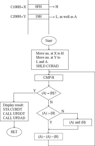
Fig. 16.3 Flowchart to find the HCF
CURAD: EQU FFF7H
UPDAD: EQU 06BCH

       LDA X
       MOV H, A ;;Load H with the number at location X.

       LDA Y
       MOV L, A ;;Load A and L with the number at location Y.
       SHLD CURAD;Store the two numbers in word location CURAD.

AGAIN: CMP H        ;Compare A and H contents.
   JZ EXIT      ;If they are same, jump to EXIT with HCF value in A.

       JNC DOWN_A ;If A is larger, jump to DOWN_A, to reduce it.

  MOV L, A
  MOV A, H
  MOV H, L          ;;;Else, i.e. if A is smaller, exchange A and H.

DOWN_A: SUB H   ;Reduce A value by H contents.
        JMP AGAIN   ;Jump to AGAIN.

        ;When we come out of this loop, HCF value will be in A.
EXIT:   STA CURDT
    CALL UPDDT  ;;Display the HCF in data field.
    CALL UPDAD  ;Display the two numbers in address field.
    HLT         ;Use HLT only in keyboard mode,
                ;and preferably RST 1 in serial mode.
16.4 CHECK FOR ‘2 OUT OF 5’ CODE
Write an 8085 assembly language program to check if the byte at location X belongs to ‘2 out of 5’ code or not. It belongs to ‘2 out of 5’ code, if the MS 3 bits are 000, and there are two 1s in the LS 5 bits. Display in the address field, the number and FF in the case of valid code, or the number and 00 in the case of invalid code.
Flowchart for solving the problem is shown in Fig. 16.4.
16.4.1 PROGRAM TO CHECK FOR ‘2 OUT OF 5’ CODE
;FILE NAME C:ALSCHKCODE.ASM

  ;8085 ALP TO CHECK IF THE BYTE AT X BELONGS TO ‘2 OUT OF 5’ CODE OR NOT.
      ;( IT IS VALID CODE IF THE MS 3 BITS ARE 000, AND THERE ARE TWO 17'S IN
      ;THE LS 5 BITS )

      ;PROGRAM DISPLAYS IN THE ADDRESS FIELD, THE NUMER AND FF
      ;IF IT IS VALID CODE, ELSE DISPLAYS THE NUMBER AND 00

      ORG C100H
X:    DB 14H

      ORG C000H

CURAD:EQU FFF7H
UPDAD:EQU 06BCH

      LDA X
      MOV H,A      ;;Load A and H with the number to be tested.

      MVI L, 00H   ;Load L with 00. It will be changed later to FF
                   ;if the number belongs to ‘2 out of 5’ code.

      ANI 11100000B;Reset to 0 the LS 5 bits of A,
                   ;with MS 3 bits unchanged.

      JNZ ZERO     ;If MS 3 bits are not 000 jump to ZERO to indicate
                   ;that the number does not belong to ‘2 out of 5’ code

      MOV A, H     ;Load A with the number to be tested, present in H.

      MVI C, 05H   ;Load C with 5, the number of bits to test.
      MVI D, 00H   ;Initialise D with 00. It will finally have
                   ;the number of 1's in the LS 5 bits.

LOOP: RRC          ;Rotate right Accumulator A.

      JNC NOINCD   ;If there is no Carry, jump to NOINCD,
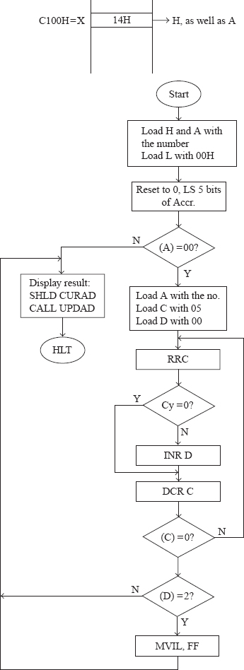
Fig. 16.4 Flowchart to check for two out of five code
INR D         ;;else, increment D.

NOINCD:DCR C       ;;Decrement the counter C.
       JNZ LOOP       ;;If not zero, jump to LOOP.
       ;When we come out of this loop, D will have.
;number of 1's in the LS 5 bits.

     MVI A,02H
       CMP D ;;Compare D with 2.
       JNZ ZERO ;If D is not equal to 2, jump to ZERO.

       MVI L, FFH ;If D is equal to 2, load L with FFH.

     ;At this point H will have the number, and L will be FF or 00
      ;depending on whether the number belongs to ‘2 out of 5’ code or not.

ZERO: SHLD CURAD
CALL UPDAD         ;;Display result in address field.
HLT                 ;Teminate with HLT only for keyboard mode,
                    ;and preferably with RST 1 for serial mode.
16.5 CONVERT ASCII TO BINARY
Write an 8085 assembly language program to convert an ASCII hex character to the equivalent binary. ASCII hex number is at location X. Display the ASCII hex number and its binary equivalent in the address field.
Flowchart for solving the problem is shown in Fig. 16.5.
16.5.1 PROGRAM TO CONVERT ASCII TO BINARY
;FILE NAME C:ALSASC_BIN.ASM

  ;8085 ALP TO CONVERT AN ASCII HEX CHARACTER TO BINARY.
  ;ASCII HEX NUMBER IS AT LOCATION X. DISPLAY THE ASCII NUMBER
  ;AND ITS BINARY(HEX) EQUIVALENT IN THE ADDRESS FIELD.

  ;Some details about ASCII codes

  ;ASCII code for character ‘0’ is 30H, for ‘1’ it is 31H, etc
  ;and for ‘9’ it is 39H. The ASCII code for ‘A’ is 41H, for ‘B’
  ;it is 42H, etc and for character ‘F’ it is 46H.

  ;So, to convert ASCII to hexadecimal value, we have to subtract
  ;30H in case it is a character from ‘0’ to ‘9’, and subtract 37H
  ;in case it is a character from ‘A’ to ‘F’.

  ;For example, 42H - 37H 5 0BH, where 42H is ASCII code for ‘B’.

  ;NOTE: We display Hexadecimal value, instead of binary because
  ;to display binary we need more number of 7 segment L.E.D.s than
  ;available on the kit. Also, display in binary is more difficult
  ;to comprehend.

           ORG C100H
  X:       DB 43H

           ORG C000H

  CURAD: EQU FFF7H
  UPDAD: EQU 06BCH

Fig. 16.5 Flowchart to convert ASCII hex to binary
   LDA X
   MOV H, A ;;Load A and H with contents of location X.

   SUI 30H ;Subtract 30H from A.
   CPI 0AH ;Compare result with 0AH.
   JC NUMB ;If A value is 00 to 09, jump to NUMB.
           ;Then, ASCII code corresponds to ‘0’ to ‘9’,

   SUI 07H ;else, subtract 07H again
           ;because ASCII code corresponds to ‘A’ to ‘F’.

           ;At this point A has the hexadecimal number corresponding
           ;to the ASCII code in H.

NUMB: MOV L, A

      SHLD CURAD
      CALL UPDAD;;;Display ASCII code and its hexadecimal
                  ;equivalent in the address field.

      HLT
16.6 CONVERT BINARY TO ASCII
Write an 8085 assembly language program to convert a two-digit hexadecimal number to two equivalent ASCII codes. The two-digit hexadecimal number is at location X. Display the hexadecimal number in the data field and its equivalent ASCII code (2 bytes) in the address field.
Flowchart for solving the problem is shown in Fig. 16.6.

Fig. 16.6 Flowchart to convert two-digit hex to two ASCII bytes
16.6.1 PROGRAM TO CONVERT TWO-DIGIT HEX TO TWO ASCII VALUES
;FILE NAME C:ALSBIN_ASC.ASM

      ;8085 ALP TO CONVERT A 2 DIGIT HEXADECIMAL NUMBER TO
      ;EQUIVALENT TWO ASCII CODES. THE 2 DIGIT HEXADECIMAL NUMBER IS
      ;AT LOCATION X. DISPLAY THE HEXADECIMAL NUMBER IN THE DATA FIELD
      ;AND ITS EQUIVALENT ASCII CODE IN THE ADDRESS FIELD.

      ORG C100H
X:    DB 2BH

      ORG C000H

CURDT:EQU FFF9H
UPDDT:EQU 06D3H
CURAD:EQU FFF7H
UPDAD:EQU 06BCH

      LDA X
      STA CURDT
      MOV B, A ;;;Load A and B from location X. Store A in CURDT.

      RRC
      RRC
      RRC
      RRC ;;;;Rotate right A four times
             ;to exchange LS and MS digits of A.
      CALL HEX_ASC;Convert LS digit of the number in A to ASCII.
                  ;Result will be in A. Thus A will have ASCII
                  ;code of MS digit of number because of exchange.

      MOV H, A    ;Load H with ASCII code of MS digit.

      MOV A, B    ;Load A from B. So A will have original number.
      CALL HEX_ASC;Convert LS digit of the number in A to ASCII.
                  ;Result will be in A. Thus A will have ASCII
                  ;code of LS digit of number.

      MOV L, A    ;Load L with ASCII code of LS digit.

      SHLD CURAD
      CALL UPDAD  ;;Display ASCII codes in address field.
      CALL UPDDT   ;Display the number in data field.
      HLT

      ;The subroutine shown below converts the LS hex digit in A, to its
      ;equivalent ASCII code. Result will be in A. To get the ASCII code we
      ;have to add 30H, if the character is in the range ‘0’ to ‘9’, and add
      ;37H if the character is in the range ‘A’ to ‘F’.

HEX_ASC:
      ANI 0FH   ;Make MS 4 bits of A as 0000.
      CPI 0AH   ;Compare LS hex digit of A with 0AH.
      JC NUMB   ;If LS hex digit of A is 0 to 9, jump to NUMB
                ;which adds 30H to get the ASCII code.

      ADI 07H   ;else add 07H, and then proceed to NUMB so that
                ;effectively 37H is added to get ASCII code.

NUMB: ADI 30H   ;Add 30H so that A will have the ASCII code.
RET             ;Return to calling program
16.7 CONVERT BCD TO BINARY
Write an 8085 assembly language program to convert a two-digit BCD number to binary. The two-digit BCD number is at location X. Display the BCD number and its binary equivalent in the address field.
Generally, there is more than one way of solving a given problem. To illustrate this idea, two methods of converting a BCD number to binary are described in this section. A flowchart for the first method of solving the problem is shown in Fig. 16.7a.

Fig. 16.7a Flowchart to convert a two-digit BCD to binary — Method 1
16.7.1 PROGRAM TO CONVERT A TWO-DIGIT BCD TO BINARY–METHOD 1
;FILE NAME C;ALSBCD_BIN.ASM

  ;8085 ALP TO CONVERT A 2 DIGIT BCD NUMBER TO BINARY.
  ;THE 2 DIGIT BCD NUMBER IS AT LOCATION X. DISPLAY THE BCD NUMBER
  ;AND ITS BINARY(HEX) EQUIVALENT IN THE ADDRESS FIELD.

  ;There are many ways of solving this problem. The method adopted
  ;here is as follows. Registers A and L are initialised to 00. Then
  ;A is incremented in decimal, and L is incremented in hexadecimal
  ;till A equals the given BCD value. Then L will have the equivalent
  ;hexadecimal value.

  ORG C100H
X:DB 95H

ORG C000H

CURAD:EQU FFF7H
UPDAD:EQU 06BCH

      LDA X
      MOV H, A     ;;Load H and A with BCD number from location X.

      MVI L, 00H    ;Initialise L with 00H. Finally L will have
                    ;equivalent Hexadecimal number.
      CPI 00H       ;Compare the BCD number with 00.
      JZ EXIT       ;If the BCD number is 00, jump to EXIT
                    ;to result display in the address field.

      MVI A, 00H    ;Initialize A with 00.

REPEAT:
      ADI 01H
      DAA    ;;Increment A in decimal system.
      INR L  ;Increment L in binary(hex) system.
      CMP H  ;Compare A with the BCD number to be converted.

      CMC    ;As A will be less than H to start with, the
             ;comparison results in Cy becoming 1. So complement
             ;Cy flag to make it 0. Else, DAA gives wrong result.

      JNZ REPEAT;If A is not equal to BCD number, jump to REPEAT.

      ;When we come out of this loop, A and H will have the
      ;BCD number, and L will have equivalent hexadecimal number.

EXIT: SHLD CURAD
CALL UPDAD ;;Display the result in address field
HLT
Flowchart for the second method of solving the problem is shown in Fig. 16.7b.

Fig. 16.7b Flowchart to convert a two-digit BCD to binary — Method 1
16.7.2 PROGRAM TO CONVERT A TWO-DIGIT BCD TO BINARY–METHOD 2
;FILE NAME C:ALSBCDBIN2.ASM

            ;8085 ALP TO CONVERT A 2 DIGIT BCD NUMBER TO BINARY
            ;THE 2 DIGIT BCD NUMBER IS AT LOCATION X. DISPLAY THE BCD NUMBER
            ;AND ITS BINARY(HEX) EQUIVALENT IN THE ADDRESS FIELD.
;We use the following method for converting BCD to binary. Suppose
            ;we have the BCD number 45. This is 4 x 10 1 5. Or in hexadecimal,
            ;it is equivalent to 4 x 0AH 1 5. Thus the method involves multi-
            ;plying by 0AH the MS digit of the number, and then adding the
            ;LS digit of the number.

            ORG C100H
    X:      DB 95H

            ORG C000H

  CURAD:    EQU FFF7H
  UPDAD:    EQU 06BCH
            LDA X
            MOV H, A;;Load A and H with the BCD number at location X.
            ANI 0FH  ;Make the MS 4 bits of A as 0000.
                     ;Thus A will now have the LS digit of the number.

            MOV B, A ;Load B with LS digit of the number.
            MOV A, H ;Reload A with the 2 digit BCD number in H.
            ANI F0H  ;Make the LS 4 bits of A as 0000.
            RRC
            RRC
            RRC
            RRC   ;;;;Exchange LS and MS digits of A.
                     ;Thus A will now have the MS digit of the number.

            MOV C, A ;Load C with MS digit of the number.

            ;The following 4 instructions multiply C contents with 0AH.

            MVI A, 00H    ;Initialise A with 00H.
     AGAIN: ADI 0AH       ;Add 0AH.
            DCR C         ;Decrement C.
            JNZ AGAIN     ;If not zero, jump to AGAIN.

            ;When we are out of this loop, A will have C contents x 0AH.
            ADD B    ;Add B contents. Now A will have equivalent Hex value.
            MOV L, A ;Load L with the result in A.

            SHLD CURAD

            CALL UPDAD ;;Display in address field, the BCD number
                        ;and its Hexadecimal value.

            HLT
16.8 CONVERT BINARY TO BCD
Write an 8085 assembly language program to convert an 8-bit binary number to equivalent BCD number. The binary number is at location X. Display the binary number in the data field, and its equivalent BCD number in the address field.
There are various methods of solving this problem. Three of them are described in this text. A flowchart for the first method of solving the problem is shown in Fig. 16.8a.
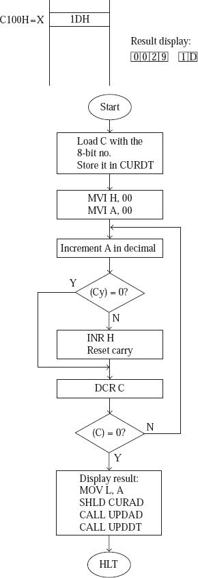
Fig. 16.8a Flowchart to convert an 8-bit binary to BCD — Method 1
16.8.1 PROGRAM TO CONVERT AN 8-BIT BINARY TO BCD–METHOD 1
;FILE NAME C:ALSBIN_BCD.ASM
  ;8085 ALP TO CONVERT A 8 BIT BINARY NUMBER TO
  ;EQUIVALENT BCD NUMBER. THE BINARY NUMBER IS AT LOCATION X.
  ;DISPLAY THE BINARY NUMBER IN THE DATA FIELD
  ;AND ITS EQUIVALENT BCD NUMBER IN THE ADDRESS FIELD.

  ;The method used in this program is as follows. Suppose we want to
  ;convert CF to equivalent BCD. We move this number to a register,
  ;say, C register. We load A with 00. Now we keep decrementing C in
  ;hexadecimal and incrementing A in decimal till C becomes 00. If
  ;there is a Carry during incrementing of A, we accumulate these
  ;carries in another register, say H. Finally, H and A will have
  ;the BCD equivalent.

  ORG C100H
X:DB 1DH

  ORG C000H
  CURDT:EQU FFF9H
  UPDDT:EQU 06D3H
  CURAD:EQU FFF7H
  UPDAD:EQU 06BCH

      LDA X
      STA CURDT
      MOV C, A ;;;Load C from location X. Store it in CURDT.

      MVI H, 00H ;Initialise H to 0. Finally H will have
                 ;MS byte of BCD result.

      MVI A, 00H ;Initialise A to 0. Finally A will have
                 ;LS byte of BCD result.

      ;The next 7 instructions decrement C in hexadecimal, and
      ;increment A in decimal till C becomes 00. During
      ;incrementing of A if there is a Cy, H is incremented.

AGAIN: ADI 01H
       DAA   ;;Increment A in decimal.
       JNC SKIP ;If Cy 5 0, jump to SKIP.

       INR H
       CMC      ;;If Cy 5 1, increment H and reset Cy.

SKIP: DCR C     ;Decrement C.
       JNZ AGAIN;If not zero jump to AGAIN.

       ;When we come out of this loop, H and A will have the
       ;MS and LS byte respectively of the BCD result.

       MOV L, A
       SHLD CURAD
       CALL UPDAD;;;Display equivalent BCD in address field.
       CALL UPDDT  ;Display Hexadecimal number in data field.
       HLT
Flowchart for the second method of solving the problem is shown in Fig. 16.8b.

Fig. 16.8b Flowchart to convert an 8-bit binary to BCD — Method 2
16.8.2 PROGRAM TO CONVERT AN 8-BIT BINARY TO BCD–METHOD 2
;FILE NAME C:ALSBINBCD2.ASM
   ;8085 ALP TO CONVERT A 8 BIT BINARY NUMBER TO
   ;EQUIVALENT BCD NUMBER. THE BINARY(HEX) NUMBER IS AT LOCATION X.
   ;DISPLAY THE BINARY(HEX) NUMBER IN THE DATA FIELD
   ;AND ITS EQUIVALENT BCD NUMBER IN THE ADDRESS FIELD.

   ;The method used is as follows. Suppose we have CF as the 8 bit
   ;hexadecimal number. It is same as C x 16 1 F. Or, in decimal it
   ;is 12 x 16 1 15 5 207. So, we first convert the LS digit to BCD.
   ;Then we multiply MS digit by 16 in decimal notation, and finally
   ;add these two BCD numbers.

       ORG C100H
X:     DB 1DH

       ORG C000H
CURDT: EQU FFF9H
UPDDT: EQU 06D3H
CURAD: EQU FFF7H
UPDAD: EQU 06BCH

       LDA X
       STA CURDT
       MOV B, A;;;Load A from location X. Store it in CURDT and B.

       ;The next 4 instructions convert the LS digit of A into
          ;its equivalent BCD value
       ANI 0FH ;Make MS 4 bits of A as 0000 (mask MS digit of A).
       ADI 00H ;Add 00 so that flags are affected based on A value.
       DAA     ;Decimal adjust.
       MOV C, A;Save result in C.

       ;The next 7 instructions save the MS digit of number in D
       MOV A, B;Load A from saved value in B.
       ANI F0H ;Mask LS digit of A.
       RRC
       RRC
       RRC
       RRC ;;;;Exchange LS and MS digits of A.
              ;Thus A will have MS digit of the number.
       MOV D,A;Save MS digit of the number in D.

       MVI H, 00H ;Initialise H with 00. Finally H will have
                  ;MS byte of result of conversion.
       MVI A, 00H ;Initialise A with 00. Finally A will have
                  ;LS byte of result of conversion.
       ;The next 7 instructions perform contents of D x 16 in
       ;decimal notation. Result will be in H and A.

AGAIN: ADI 16H
       DAA    ;Add 16 decimal to A.
       JNC SKIP ;If Cy 5 0, jump to SKIP.
INR H
       CMC   ;;If Cy 5 1, increment H and make Cy 5 0. If Cy
             ;is not reset to 0, DAA will give wrong result.

 SKIP: DCR D ;Decrement counter D.
       JNZ AGAIN ;If not zero, jump to AGAIN.

       ;When we come out of this loop, we will have in H and A
       ;MS digit of number x 16 in decimal notation.

       ;The next 5 instructions add C contents to A in decimal
       ;notation. If Cy becomes 1, then H is incremented.

       ADD C    ;Add C to A.
       DAA      ;Decimal adjust to get LS byte of BCD result.
       MOV L, A ;Save result in L.

       JNC DISP
       INR H ;;Increment H if Cy 5 1.
              ;H contains MS byte of BCD result.

       ;At this point, HL will have the equivalent BCD value.

DISP: SHLD CURAD
      CALL UPDAD;;Display BCD value in address field.
      CALL UPDDT ;Display the Hex number in data field.
      HLT
16.8.3 PROGRAM TO CONVERT AN 8-BIT BINARY TO BCD–METHOD 3
Flowchart for the third method of solving the problem is shown in Fig. 16.8c.
;FILE NAME C:ALSBINBCD3.ASM

       ;8085 ALP TO CONVERT A 8 BIT BINARY NUMBER TO
       ;EQUIVALENT BCD NUMBER. THE BINARY NUMBER IS AT LOCATION X.
       ;DISPLAY THE BINARY NUMBER IN THE DATA FIELD
       ;AND ITS EQUIVALENT BCD NUMBER IN THE ADDRESS FIELD.

       ;The method used for conversion is as follows. Suppose we want
       ;to convert CF to equivalent BCD. First of all, we find out how
       ;many 1001's are present in the number, by repeatedly subtracting
       ;64H (5100) from the number, till the number becomes less than
       ;64H. Let us say, we store this result in register H.
       ;Next, we find out how many 10's are present in the number, by
       ;repeatedly subtracting 0AH (510) from the number, till the number
       ;becomes less than 0AH. Let us say, we store this result in
       ;register L. Once we know the number of 100's, number of 10's
       ;and the units value, we have the equivalent BCD number.
       ORG C100H

X:     DB FFH

       ORG C000H
CURDT: EQU FFF9H
UPDDT: EQU 06D3H
CURAD: EQU FFF7H

Fig. 16.8c Flowchart to convert an 8-bit binary to BCD — Method 3
UPDAD: EQU 06BCH
       LDA X
       STA CURDT   ;;Load A from location X. Store in CURDT.
       MVI H, 00H  ;Initialise H with 00. H will finally have the
                   ;number of 100's in the BCD result.
       MVI L, 00H  ;Initialise L with 00. L will finally have the
                   ;number of 10's in the BCD result.
;The next 5 instructions store in H the number of 100's.
REP1:  CPI 64H          ;Compare A with 64H i.e. 100 decimal.
       JC REP2          ;If , 100, jump to REP2 to find number of 10's.

       INR H            ;If >5 100, increment H.
       SUI 64H          ;Decrement A by 100 decimal.
       JMP REP1         ;Jump to REP1.

       ;When we are out of this loop, H will have number of 100's
       ;and A contents would have become less than 100.

       ;The next 5 instructions store in L the number of 10's.

REP2:  CPI 0AH       ;Compare A with 0AH i.e. 10 decimal.
       JC EXIT       ;If <10, jump to EXIT.

       INR L         ;If >= 10, increment L.
       SUI 0AH       ;Decrement A by 10 decimal.
       JMP REP2      ;Jump to REP2.

       ;When we are out of this loop, L will have number of 10's
       ;and A contents would have become less than 10.
EXIT:   MOV B, A       ;Save in B the units value of BCD result.
        MOV A, L       ;Load A with number of 10's in BCD result.
        RLC
        RLC
        RLC
        RLC        ;;;;Move this information to MS digit of A,
                      ;with LS digit of A as 0.

        ADD B         ;This results in A having number of 10's in MS
                                    ;digit, and units value of result in LS digit.
        MOV L, A      ;Save A value in L.
                      ;Thus the total BCD result is now in HL.

        SHLD CURAD
        CALL UPDAD;;Display BCD equivalent in address field.
        CALL UPDDT ;Display Hexadecimal value in data field.
        HLT
16.9 CHECK FOR PALINDROME
Write an 8085 assembly language program to check if the 8-bit number at location X is a palindrome or not. Display the number and the result in the address field. If it is a palindrome the result should be FF, else 00.
Flowchart for the method of solving the problem is shown in Fig. 16.9.

Fig. 16.9 Flowchart to check for palindrome
16.9.1 PROGRAM TO CHECK FOR PALINDROME
;FILE NAME C:ALSPALIN.ASM
       ;8085 ALP TO CHECK IF THE 8 BIT NUMBER AT LOCATION X
       ;IS A PALINDROME OR NOT. DISPLAY THE NUMBER AND THE RESULT IN THE
       ;ADDRESS FIELD. IF IT IS A PALINDROME THE RESULT IS FF, ELSE 00.

       ORG C100H
X:     DB BDH

       ORG C000H
CURAD: EQU FFF7H
UPDAD: EQU 06BCH

       LDA X
       MOV H, A   ;;Load H from location X.
       MVI C, 08H ;Load C with 8. C is used as down counter.

AGAIN: MOV A,H
       RLC
       MOV H, A ;;;Rotate left contents H. A bit of H register
                  ;moved to Cy starting with MS bit.
       MOV A, D
       RAR
       MOV D, A ;;;Rotate right through Carry contents of D. The bit moved
                  ;out of H register enters D register through the MS bit.

       DCR C      ;Decrement C.
       JNZ AGAIN  ;If not zero, jump to AGAIN.

       ;By the time we come out of the loop, D register will have
       ;the reverse of the byte in location X. And because of 8
       ;rotations, H register will have the original number.

       MOV A, H
       CMP D   ;;Compare the number and its reverse.
       JZ PALIN ;If they are same, jump to PALIN.

       MVI L, 00H ;Load L with 00, if the byte is not a palindrome.
       JMP EXIT   ;Jump to EXIT to display result.

PALIN: MVI L,FFH ;Load L with FF, if the byte is not a palindrome.

EXIT:  SHLD CURAD
       CALL UPDAD;;Display result in the address field.
       HLT
16.10 COMPUTE THE LCM OF TWO 8-BIT NUMBERS
Write an 8085 assembly language program to compute the LCM of two 8-bit numbers stored in locations X and Y. Display the result in the address field.
Flowchart for the method of solving the problem is shown in Fig. 16.10.

Fig. 16.10 Flowchart to compute the LCM of two bytes
16.10.1 PROGRAM TO COMPUTE LCM
;FILE NAME C:ALSLCM.ASM

       ;8085 ALP TO DETERMINE THE LCM OF TWO 8 BIT NUMBERS STORED IN
       ;LOCATIONS X AND Y. DISPLAY THE RESULT IN THE ADDRESS FIELD

       ;The method used is as follows. Let us say, the two numbers are
       ;25 and 15. We divide the first number by the second number. If
       ;there is no remainder, then the first number is the LCM. But in
;this case, there is a remainder. So we try to see if the next
       ;multiple of 25, i.e. 2 x 25 5 50 is the LCM. Again, 50 does not
       ;divide exactly by 15, and so 50 is not the LCM. Next we try if
       ;3 x 25 5 75 is the LCM. 75 divides exactly by 15. Thus 75 is
       ;the LCM of 25 and 15.
       ORG C100H
X:     DB 19H

       ORG C200H
Y:     DB 0FH

       ORG C000H

CURAD: EQU FFF7H
UPDAD: EQU 06BCH

       LXI H, X
       MOV C, M
       MVI B, 00;;;Load BC with the 8 bit number at location X.

       ;The next 5 instructions load DE with the 2's complement
       ;of number at Y, i.e. negative of the number at Y.

       LDA Y
       CMA
       MOV E, A ;;;Load E with 1's complement of the number at Y.
       MVI D, FFH ;Now DE contains 1's complement of number at Y.
       INX D            ;DE contains 2's complement of the number at Y.

       LXI H, 0  ;Initialise HL with 0. Finally HL will have LCM.

NEXT:  DAD B       ;Add to HL the first number. Every time through
                   ;the loop, HL will be loaded with the next
                   ;multiple of the first number.

       SHLD CURAD;Store result in word location CURAD.

       ;The next 6 instructions perform the following. It repeatedly
       ;subtracts the second number from HL till result becomes zero or
       ;negative. If result is zero, jumps to EXIT, and if negative
       ;jumps to SKIP. Note that result is negative, if Cy 5 0.

AGAIN: DAD D    ;Subtract from HL the second number.
       JNC SKIP ;If result is negative, jump to SKIP.

       MOV A, H
       ORA L
       JZ EXIT ;;;If result in HL is 0000H, jump to EXIT.

       ;DAD instruction does not affect flags except Cy. So
       ;we have used indirect method to check for zero result.

       JMP AGAIN ;If result is positive, jump to AGAIN.

       ;The next 2 instructions result in reloading HL from CURAD
       ;and jumping to NEXT, so that HL will have the next multiple
       ;of the first number.
SKIP:  LHLD CURAD
       JMP NEXT ;;Reload HL from CURAD and jump to NEXT.

       ;At this point we have in HL and word location CURAD, the LCM.

EXIT:  CALL UPDAD ;Display LCM in the address field.
       HLT
16.11 SORT NUMBERS USING BUBBLE SORT
Write an 8085 assembly language program to sort N 1-byte binary numbers in ascending order, using bubble sort. N is stored at location X, and the numbers from location X+1.
Flowchart for the method of solving the problem is shown in Fig. 16.11.
16.11.1 PROGRAM TO PERFORM SORTING USING BUBBLE SORT
;FILE NAME C:ALSBUBSRT.ASM

       ;8085 ALP TO SORT N ONE BYTE BINARY NUMBERS IN ASCENDING
       ;ORDER USING BUBBLE SORT. N IS STORED AT LOCATION X, AND
       ;THE NUMBERS FROM LOCATION X+1.

       ;MODIFY THE SAME PROGRAM TO SORT IN DESCENDING ORDER.

       ORG C100H
X:     DB 04H,33H,22H,44H,11H

       ORG C000H

       LXI H, X
       MOV C, M   ;;Load C from memory location X.
       DCR C       ;Decrement C. C now has the number
                   ;of passes still to be performed.

OUTLOOP:
        MVI E, 01H     ;Load E with 1. E contains one more than the
                       ;number of exchanges made in a pass so far.

        MOV B, C       ;Load B from C contents. B now has the number
                       ;of comparisons still to be performed in a pass.
        INX H          ;Point HL to the first element of the array.

INLOOP:
        MOV A, M       ;Load A from memory pointed by HL.
        INX H          ;Point HL to next element of array.
        CMP M          ;Compare A (previous element) and
                       ;next element of the array.

        JC SKIP        ;If (previous element is , next element), then
                       ;jump to SKIP, without performing exchange.

        ;CHANGE ‘JC SKIP’ TO ‘JNC SKIP’ FOR SORTING IN DESCENDING ORDER
;The following 5 instructions perform exchange of previous and

Fig. 16.11 Flowchart to perform sorting using bubble sort
;next elements.

      MOV D, M      ;Save next element in D register.
      MOV M, A      ;Load in next element position the previous element.
      DCX H         ;Point HL to previous element.
      MOV M, D      ;Previous element position loaded with value in D.
      INX H         ;Point HL to next element.

      INR E         ;Increment E, as an exchange has taken place.

SKIP: DCR B         ;Decrement B, as a comparison in a pass is over.
      JNZ INLOOP    ;If non zero, jump to INLOOP to
                    ;perform next comparison.

      ;When we are out of this inner loop, it means we have
      ;completed a pass of the array. Then we check if any
      ;exchanges were made during the pass.

      DCR E          ;Decrement E
      JZ EXIT        ;If E value is zero, it means no exchanges were
                     ;made in this pass. So jump to EXIT.

      LXI H, X      ;Load HL with X. From X+1, the array begins.
      DCR C         ;Decrement C, as a pass through the array is over.
      JNZ OUTLOOP   ;If non zero, jump to OUTLOOP to
                    ;perform next pass.

EXIT: HLT           ;Halt, as the sorting is complete.
16.12 SORT NUMBERS USING SELECTION SORT
Write an 8085 assembly language program to sort N 1-byte binary numbers in ascending order, using selection sort. N is stored at location X, and the numbers from location X+1.
Flowchart for the method of solving the problem is shown in Fig. 16.12.
16.12.1 PROGRAM TO PERFORM SORTING USING SELECTION SORT
;FILE NAME C:ALSSELSORT.ASM

;8085 ALP TO SORT N ONE BYTE BINARY NUMBERS IN ASCENDING
;ORDER USING SELECTION SORT. N IS STORED AT LOCATION X, AND

     ;THE NUMBERS FROM LOCATION X+1.

     ;MODIFY THE SAME PROGRAM TO SORT IN DESCENDING ORDER
     ORG C000H
X:   EQU C100H

     ;In this program, we have not indicated data values. The user is
     ;required to provide them, using the kit in keyboard mode, or
     ;using the PC in serial mode.

            ;NOTE: It is assumed for simplicity that
            ;X is an address with last 2 digits as 00H.

Fig. 16.12 Flowchart to perform sorting using selection sort
LXI H, X
      MOV C, M    ;;Load C from location X.
      DCR C        ;Decrement C. C indicates the number of
                  ;passes still to be made.

OUTLOOP:
       MOV B, C    ;Load B from C. B indicates the number of
                   ;comparisons still to be made in a pass.
       INX H       ;Point HL to the first element of the array.
       MOV A, M    ;Load A with the first element of the array. By the
                   ;end of the pass, A will have the largest element.

INLOOP:INX H       ;Point HL to next element of array.
       CMP M       ;Compare A (previous element) and next element.
       JNC SKIP    ;If (A >= next element) jump to SKIP.

       ;CHANGE ‘JNC SKIP’ TO ‘JC SKIP’ FOR SORTING IN DESCENDING ORDER

       MOV A, M
       MOV E, L    ;;If (A      next element), load A with next element,
                    ;and E with position of next element.

SKIP:  DCR B      ;Decrement B, as a comparison is over.
       JNZ INLOOP ;If nonzero, perform one more comparison.

       ;At this point, a pass is completed. A has the largest element,
       ;and E has the position in the array of the largest element. The
       ;next 4 instructions exchange the largest element in the array
       ;with the last element of the array.

       MOV D, M ;Save in D, the last element of the array.
       MOV M, A ;Last location of array loaded with A.
       MOV L, E ;Load HL with saved position of the largest element.
       MOV M, D ;Load this memory with the saved value in D.

       LXI H, X     ;Load HL with X. From X+1, the array begins.
       DCR C        ;Decrement C, as a pass is over.
       JNZ OUTLOOP  ;If nonzero, perform one more pass.
       HLT          ;Halt, as sorting is over.
16.13 SIMULATE DECIMAL UP COUNTER
Write an 8085 assembly language program to perform as a decimal up counter (from 00 to 99). The count should be incremented every half second, and is to be displayed in the data field.
Flowchart for the method of solving the problem is shown in Fig. 16.13.

Fig. 16.13 Flowchart to simulate decimal up counter
16.13.1 PROGRAM TO SIMULATE DECIMAL UP COUNTER
;FILE NAME C:ALSUPCNTR.ASM

       ;8085 ALP TO PERFORM AS A DECIMAL UP COUNTER (FROM 00 TO 99).
       ;THE COUNT SHOULD BE INCREMENTED EVERY HALF SECOND, AND
       ;THE COUNT IS TO BE DISPLAYED IN THE DATA FIELD, AND THE
       ;OPERATION SHOULD REPEAT ENDLESSLY.

       ORG C000H

CURDT: EQU FFF9H
UPDDT: EQU 06D3H
       MVI A, 00H      ;Initialise A with 00.

REP:   STA CURDT       ;Store A value in CURDT.
       CALL UPDDT      ;Display in the data field contents of CURDT.

       CALL DELAY      ;Generate a delay of 0.5 seconds

       LDA CURDT       ;Reload A from location CURDT.
       ADI 01H
       DAA             ;;Increment A in decimal notation.
       JMP REP         ;Jump to REP.
    ;------ Subroutine to generate a delay of 0.5 second. Its
    ;------ working is explained at the end of this program.

  DELAY:LXI B, FFFFH  ;Load BC with FFFFH.
  AGAIN:DCX B         ;Decrement BC. It does not affect flags.
        MOV A, B
        ORA C         ;So, perform OR of B and C registers.
        JNZ AGAIN     ;If not zero, jump to AGAIN.
        RET           ;Return, after generating delay of 0.5 second.
Note: Replace ‘JMPREP’ with the following three instructions, if it is required to stop after counting upto 99.
CPI 00H
       JNZ REP
       HLT
16.13.2 GENERATION OF TIME DELAY
There are times when we are required to generate time delays. In this example, we want the count value to change once every half second. Later in the chapter, we simulate a real time clock, where the time display should change once every second. Such time delays can be generated by a microprocessor. The principle behind time delay generation by the microprocessor is as follows. Execution of every instruction needs some clock cycles. Thus, to generate the required time delay, a microprocessor will have to execute the required number of instructions. This is the principle of time delay generation by the microprocessor.
NOP instructions for time delay: The immediate reaction will be to use NOPinstructions to generate the required time delay. Each NOPinstruction uses four clocks for fetching, decoding, and executing. In the discussion that follows, it is assumed that 8085 is working with a crystal frequency of 6 MHz, and as such with an internal frequency of 3 MHz. Thus each clock period is one-third of a microsecond. In such a case, a NOPinstruction needs only 1.33μs for execution. Even if we use 64K NOP instructions, which is the maximum possible in memory, the time delay would only be 64K × 1.33 μs = about 86μs. Also, the program size has become too much, for too little work done. Thus, we use a series of NOP instructions only when our interest is to generate small time delays of a few microseconds.
Use of an 8-bit register as counter in a loop: A much better way to generate a larger time delay with a smaller program size, is to execute a series of instructions repetitively in a loop. An example is shown below.
MVI C, FFH    ;Uses 7 T states.
REP:DCR C        ;Uses 4 T states.
     JNZ REP     ;Uses 10 T states in the case of jump
                 ;and 7 T states in the case of no jump.
     RET         ;Uses 10 T states.
In this example, C is loaded with maximum possible value of FFH. Then, C is decremented. If result is non-zero, the decrement operation is repeated. The program is quite short, and generates delay of 1.191μs, as explained below. By the time we come out of the loop, the number of T states used up will below.
7 [(4 + 10) * FF]-3 + 10
= 14+ 14 * FF
=3584
where 3 is used to take into account only seven T states used instead of ten T states for the JNZ REP instruction when C is decremented to 00. Thus the time delay generated is 3584 * 1/3μs 1195μs.
If we need delays smaller than 1195μs, we load the count register with a proportionately small value. If we need larger delay than 1195μs, we have to use a loop inside a loop as shown in the following.
MVI B, FFH
REP2:MVI C, FFH
REP1:DCR C
      JNZ REP1
      DCR B
      JNZ REP2
      RET
The user is left to calculate the delay generated in this case. It will be about 305μs. The logic can be extended further to generate any amount of delay.
Use of a register pair as counter in a loop: Instead of using an 8-bit register, we can use a register pair as counter in a loop, to generate much larger time delays using smaller program size. This is the method used in the above program to generate a half-second delay. The calculation for the delay is shown in the following.
DELAY:LXI B,FFFFH    ;Uses 10 T states
AGAIN:DCX B        ;Uses 6 T states
      MOV A, B     ;Uses 4 T states
      ORA C        ;Uses 4 T states
      JNZ AGAIN    ;Uses 10 T states for jump case
                   ;and 7 T states for no jump case
      RET          ;Uses 10 T states
Number of T states, N = 10 + (6 + 4 + 4 + 10) * FFFFH - 3 + 10
=17 + 24 * FFFFH = 1572857
Thus, time delay = 1572857 * 1/3μs 0.52428 s.
This delay is generally taken as about a half-second delay. The user is left with the exercise to compute the count value to be loaded in the register pair for exact 0.5-s delay.
However, if we use the microprocessor to generate large time delays, the microprocessor will not be available for any other operation for the entire delay time. So it is advisable to restrict the time delay generation by the microprocessor to only a few micro- or milliseconds in practical applications. For large time delays, it is better to use dedicated timer chips like Intel 8253, which is discussed in a later chapter.
16.14 SIMULATE DECIMAL DOWN COUNTER
Write an 8085 assembly language program to perform as a decimal down counter (from 99 to 00). The count should be decremented every half second, and the count is to be displayed in the data field.
Flowchart for the method of solving the problem is shown in Fig. 16.14.
16.14.1 PROGRAM TO SIMULATE DECIMAL DOWN COUNTER
;FILE NAME C:ALSDNCNTR.ASM

       ;8085 ALP TO PERFORM AS A DECIMAL DOWN COUNTER (FROM 99 TO 00).
       ;THE COUNT SHOULD BE DECREMENTED EVERY HALF SECOND, AND
       ;THE COUNT IS TO BE DISPLAYED IN THE DATA FIELD, AND THE

       ;OPERATION SHOULD REPEAT ENDLESSLY.

       ORG C000H
CURDT:EQU FFF9H
UPDDT:EQU 06D3H

Fig. 16.14 Flowchart to simulate decimal down counter
       MVI A, 99H      ;Initialise A with 99.

REP:   STA CURDT       ;Store A value in CURDT.
       CALL UPDDT      ;Display contents of CURDT in data field.

       CALL DELAY      ;Generate delay of 0.5 second.

       LDA CURDT       ;Reload A from location CURDT.

       ADI 99H
       DAA            ;;Decrement A in decimal notation by
                      ;adding 99, which is 10's complement of 01.
       JMP REP        ;Jump to REP to display the next count.

       ;------ Subroutine to generate a delay of 0.5 second.

DELAY: LXI B,FFFFH
AGAIN: DCX B
       MOV A, B
       ORA C
       JNZ AGAIN
       RET
Note: Replace ‘JMPREP’ with the following three instructions, if it is required to stop after counting down to 00.
CPI 99H
JNZ REP
HLT
16.15 DISPLAY ALTERNATELY 00 AND FF IN THE DATA FIELD
Write an 8085 assembly language program to alternately display 00 and FF in the data field, with a delay of N seconds, where N is less than or equal to 2.
Flowchart for the method of solving the problem is shown in Fig. 16.15.

Fig.16.15 To alternately display 00 and FF in the data field
16.15.1 PROGRAM TO ALTERNATELY DISPLAY 00 AND FF IN THE DATA FIELD
;FILE NAME C:ALSDISP00FF.ASM

       ;8085 ALP TO DISPLAY 00 AND FF ALTERNATELY WITH
       ;A DELAY OF N SECONDS, WHERE N <=2.

       ORG C000H
CURDT:EQU FFF9H
UPDDT: EQU 06D3H

REPT:  MVI A,00H
       CALL DISP    ;;Display 00 in the data field for 1 second.
       MVI A,FFH
       CALL DISP    ;;Display FF in the data field for 1 second.
       JMP REPT     ;Jump to REPT, to repeat the operations.

       ;The following subroutine displays the contents of Accumulator,
       ;in the data field for about 1 second.

DISP:  STA CURDT
       CALL UPDDT
       CALL DELAY
       RET

       ;The following subroutine generates a delay of about half the
       ;value present in D register. Thus, it generates 1-second delay.

DELAY: MVI D, 02H

LOOP1: LXI B, FFFFH
LOOP2: DCX B
       MOV A, B
       ORA C
       JNZ LOOP2   ;;;;;Generate delay of 0.5 second.

       DCR D         ;Decrement D.
       JNZ LOOP1     ;If nonzero, jump to LOOP1.
       RET
16.16 SIMULATE A REAL-TIME CLOCK
Write an 8085 assembly language program to simulate a real time clock, which displays hours and minutes in the address field, and seconds in the data field, using 24-hour format. Flowchart for the method of solving the problem is shown in Fig. 16.16.
16.16.1 PROGRAM TO SIMULATE A REAL-TIME CLOCK
;FILE NAME C:ALSREAL_CLK.ASM

       ;8085 ALP TO GENERATE REAL TIME CLOCK, WHICH DISPLAYS
       ;HOURS AND MINUTES IN THE ADDRESS FIELD AND SECONDS IN THE
       ;DATA FIELD (USING 24 HOUR FORMAT).

       ORG C000H

CURDT:EQU FFF9H
UPDDT:EQU 06D3H
CURAD:EQU FFF7H
UPDAD:EQU 06BCH

BEGIN:LXI H,0000H ;Initialise HL with 0000. H and L indicate
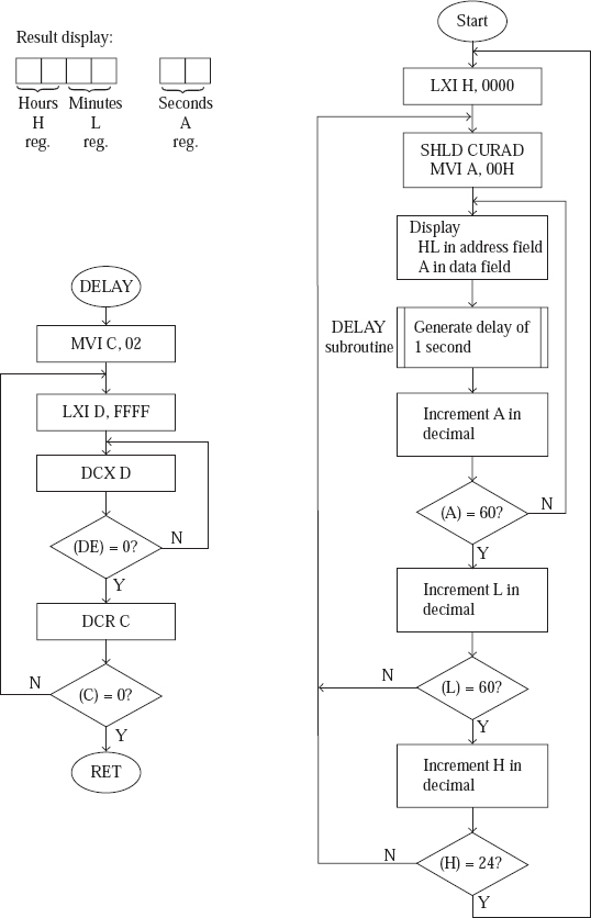
Fig.16.16 Flowchart to simulate a real-time clock
;Hours and minutes respectively.

HR_MIN:
       SHLD CURAD ;Store HL in word location CURAD.
       MVI A, 00H ;Initialise A with 00. A indicates seconds.

NXT_SEC:
       STA CURDT   ;Store A value in location CURDT.
       CALL UPDAD ;Display Hours and Minutes in address field.
CALL UPDDT ;Display Seconds in the data field.
       CALL DELAY ;Generate delay of 1 second.

       LDA CURDT  ;Reload A from CURDT.
       ADI 01H
       DAA        ;;Increment A in decimal notation.
       CPI 60H     ;Compare A and 60.
       JNZ NXT_SEC ;If A is not equal to 60, jump to NXT_SEC.

       ;When we come out of this loop, A will be 60. In such a case,
       ;it is necessary to make A as 00, and increment the Minute value,
       ;which is present in L.

       LHLD CURAD ;Reload HL from CURAD.

       MOV A, L
       ADI 01H
       DAA
       MOV L, A ;;;;Increment L in decimal notation.
       CPI 60H
       JNZ HR_MIN ;;If L value is not equal to 60, jump to HR_MIN.
                   ;A will be made 00, after jumping to HR_MIN.

       ;When we are at this point, L will be 60. In such a case, it is
       ;necessary to make L as 00, and increment the Hours value in H.

       MVI L, 00H ;Make L as 00.
       MOV A, H
       ADI 01H
       DAA
       MOV H, A     ;;;;Increment H in decimal.

       CPI 24H
       JNZ HR_MIN   ;;If H value is not equal to 24, jump to HR_MIN.
       JMP BEGIN    ;If H value is 24, jump to BEGIN.

       ;------ Subroutine DELAY to generate a time delay of 1 second

DELAY: MVI C,02H
OUTLOOP:
       LXI D, FFFFH

INLOOP:
       DCX D
       MOV A, D
       ORA E
       JNZ INLOOP

       DCR C
       JNZ OUTLOOP
       RET
Note: To test the program fully with a 1-s delay, we need 24 hours! To solve this problem, we can test the working of the seconds display, with seconds display getting updated every second. Then we change the delay such that the minutes field gets updated every second. Thus, the minutes display can be tested in just 60 more seconds. Then we change the delay such that the hours field gets updated every second. Thus, the hours display can be tested in just 24 more seconds.
To change the display in the minutes field approximately once every second, load DE pair with 0400H in this subroutine. To change the display in the hours field approximately once every second, load DE pair with 0010H in this subroutine.
- Write an 8085 assembly language program to find the largest and smallest numbers in an array of unsigned numbers. Display them in the address field.
- Write an 8085 assembly language program to convert a two-digit octal number to BCD. -Display the result in the address field.
- Write an 8085 assembly language program to convert a two-digit BCD number to octal. -Display the BCD number in the data field, and the octal number in the address field.
- Write an 8085 assembly language program to work as up counter to count in octal from 00 to 77 octal, the display in the data field changing once every second.
- Write an 8085 assembly language program to generate a delay of:
- Exactly 0.5 second;
- Exactly 1.0 second;
assuming that the internal frequency of operation is 3 MHz.
- Write an 8085 assembly language program to convert ASCII hex value to binary, using look up table approach. Display ASCII value and equivalent binary in the address field.
- Write an 8085 assembly language program to convert a two-digit hex value to two equivalent ASCII codes, using look up table approach. Display the hex value in data field and equivalent ASCII value in the address field.
- Write an 8085 assembly language program to find the LCM of two given 8-bit numbers, using a method other than that described in this chapter. Display the result in the address field.
- Write an 8085 assembly language program to check if a given byte is a palindrome or not, using a method other than that described in this text. Display the result in the address field.
- Write an 8085 assembly language program to simulate a real-time clock, which displays hours, minutes, and seconds in 12-hour format. It should display a dot at the end of the data field if the time is afternoon.