
8
Logical Group of Instructions
![]() Instructions to perform AND operation
Instructions to perform AND operation
![]() Instruction type ANA R
Instruction type ANA R
![]() Instruction type ANI d8
Instruction type ANI d8
![]() Instructions to perform OR operation
Instructions to perform OR operation
![]() Instruction type ORA R
Instruction type ORA R
![]() Instruction type ORI d8
Instruction type ORI d8
![]() Instructions to perform Exclusive OR operation
Instructions to perform Exclusive OR operation
![]() Instruction type XRA R
Instruction type XRA R
![]() Instruction type XRI d8
Instruction type XRI d8
![]() Instruction to complement accumulator
Instruction to complement accumulator
![]() Instructions to complement/set Cy flag
Instructions to complement/set Cy flag
![]() Instruction type CMC
Instruction type CMC
![]() Instruction type STC
Instruction type STC
![]() Instructions to perform compare operation
Instructions to perform compare operation
![]() Instruction type CMP R
Instruction type CMP R
![]() Instruction type CPI d8
Instruction type CPI d8
![]() Instructions to rotate accumulator
Instructions to rotate accumulator
![]() Instruction type RLC
Instruction type RLC
![]() Instruction type RAL
Instruction type RAL
![]() Instruction type RRC
Instruction type RRC
![]() Instruction type RAR
Instruction type RAR
![]() Questions
Questions
A total of 15 instruction types covering 43 instructions will be explained in this chapter. These include the various instruction types to perform AND, OR, exclusive OR, complement Accumulator, complement = set Cy flag, compare and rotate Accumulator operations.
 8.1 INSTRUCTIONS TO PERFORM ‘AND’ OPERATION
In the logical group of instructions, 8085 has instructions to perform AND, OR, Ex-OR, and NOT operations. It does not have instructions to perform NAND or NOR operations. This is because in controlling of peripherals, it is generally not required to perform NAND or NOR operations. In this section we discuss the instructions to perform AND operation.
In operations like AND, which need two operands, 8085 imposes the restriction that one of the operands must be in the Accumulator. The other operand can be one of the following.
- –Contents of an 8-bit register;
- –Contents of memory location pointed by HL pair;
- –Eight-bit immediate data.
The AND operation performs bit-wise AND of the two operands. If X is a bit of Accumulator, and Y is a bit of the other operand in the same bit position, the AND operation is performed as per the following truth table.

It can be noticed that X AND 1 = X, and X AND 0 = 0. Thus, AND operation is used for selectively resetting to 0 some bits of the Accumulator. Bits of the Accumulator that are ANDed with 0s are reset to 0, and bits of the Accumulator, which are ANDed with 1s are not changed. Thus, if it is desired to reset MS 4bits of Accumulator, AND Accumulator contents with 0FH.
The AND instruction affects the flags as follows.
- –S, P, and Z flags are updated based on the result;
- –Cy flag is reset to 0;
- –AC flag is set to 1.
8.1.1 INSTRUCTION TYPE ANA R
ANA is a mnemonic, which stands for ‘ANd Accumulator’ and ‘R’ stands for any of the following registers, or memory location M pointed by HL pair.
R = A, B, C, D, E, H, L, or M
This instruction is used to AND contents of R with Accumulator. The result of AND operation will be stored in the Accumulator. As R can have any of the eight values, there are eight opcodes for this type of instruction. It occupies only 1 byte in memory. ‘ANA E’ is an example instruction of this type. It is a 1-byte instruction. The result of execution of this instruction is shown below with an example.

Summary: ANA R (1 byte; ANA E; 8 opcodes)
8.1.2 INSTRUCTION TYPE ANI d8
ANI is a mnemonic, which stands for ‘ANd Immediate with Accumulator’ and ‘d8’ stands for any 8-bit data. This instruction is used to AND 8-bit immediate data with the Accumulator. The result of ANDing will be stored in the Accumulator. The S, P, and Z flags are affected based on the result. Cy is reset to 0, and AC is set to 1. It occupies 2 bytes in memory.
‘ANI F3H’ is an example instruction of this type. It is a 2-byte instruction. The result of execution of this instruction is shown below with an example.

Summary: ANI d8 (2 bytes; ANI F3H; 1 opcode)
8.2 INSTRUCTIONS TO PERFORM ‘OR’ OPERATION
The OR operation performs bit-wise OR of the two operands. If X is a bit of Accumulator, and Y is a bit of the other operand in the same bit position, the OR operation is performed as per the following truth table.
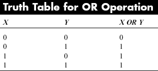
It can be noticed that X OR 1 = 1, and X OR 0 = X. Thus, OR operation is used for selectively setting some bits of the Accumulator to 1. Bits of the Accumulator, which are ORed with 1s are set to 1, and bits of the Accumulator, which are ORed with 0s are not changed. Thus, if it is desired to set MS 4bits of Accumulator, OR Accumulator contents with F0H.
The OR instruction affects the flags as follows.
- –S, P, and Z flags are updated based on the result;
- –Cy and AC flags are reset to 0.
8.2.1 INSTRUCTION TYPE ORA R
ORA is a mnemonic, which stands for ‘OR Accumulator’ and ‘R’ stands for any of the following registers, or memory location M pointed by HL pair.
R = A, B, C, D, E, H, L, or M
This instruction is used to OR contents of R with the Accumulator. The result of OR operation will be stored in the Accumulator. As R can have any of the eight values, there are eight opcodes for this type of instruction. It occupies only 1 byte in memory. ‘ORA E’ is an example instruction of this type. It is an 1-byte instruction. The result of execution of this instruction is shown below with an example.

Summary: ORA R (1 byte; ORA E; 8 opcodes)
8.2.2 INSTRUCTION TYPE ORI d8
ORI is a mnemonic that stands for ‘OR Immediate with Accumulator’ and ‘d8’ stands for any 8-bit data. This instruction is used to OR 8-bit immediate data with the Accumulator. The result of ORing will be stored in the Accumulator. The S, P, and Z flags are affected based on the result. Cy and AC are reset to 0. It occupies 2 bytes in memory. ‘ORI F3H’ is an example instruction of this type. It is a 2-byte instruction. The result of execution of this instruction is shown below with an example.
Summary: ORI d8 (2 bytes; ORI F3H; 1 opcode)
8.3 INSTRUCTIONS TO PERFORM ‘EXCLUSIVE OR’ OPERATION
The Ex-OR operation performs bit-wise Ex-OR of the two operands. If X is a bit of Accumulator, and Y is a bit of the other operand in the same bit position, the Ex-OR operation is performed as per the following truth table.
It can be noticed that X Ex-OR 1 = X*, and X Ex-OR 0 = X. Thus, Ex-OR operation is used for selectively complementing some bits of the Accumulator. Bits of the Accumulator, which are Ex-ORed with 1s are complemented, and bits of the Accumulator, which are Ex-ORed with 0s are not changed. Thus, if it is desired to complement MS 4 bits of Accumulator, Ex-OR Accumulator contents with F0H.
The Ex-OR instruction affects the flags as follows.
- –S, P, and Z flags are updated based on the result;
- –Cy and AC flags are reset to 0.
INSTRUCTION TYPE XRA R
XRA is a mnemonic that stands for ‘eXclusive OR accumulator’ and ‘R’ stands for any of the following registers, or memory location M pointed by HL pair.
R = A, B, C, D, E, H, L, or M
This instruction is used to Ex-OR contents of R with the Accumulator. The result of Ex-OR operation will be stored in the Accumulator. As R can have any of the eight values, there are eight opcodes for this type of instruction. It occupies only 1 byte in memory. ‘XRA E’ is an example instruction of this type. It is a 1-byte instruction. The result of execution of this instruction is shown below with an example.

Summary: XRA R (1 byte; XRA E; 8 opcodes)
8.3.2 INSTRUCTION TYPE XRI d8
XRI is a mnemonic that stands for ‘eXclusive OR Immediate with Accumulator’ and ‘d8’ stands for any 8-bit data. This instruction is used to Ex-OR 8-bit immediate data with the Accumulator. The result of Ex-ORing will be stored in the Accumulator. The S, P, and Z flags are affected based on the result. Cy and AC are reset to 0. It occupies 2 bytes in memory. ‘XRI F3H’ is an example instruction of this type. It is a 2-byte instruction. The result of execution of this instruction is shown below with an example.

Summary: XRI d8 (2 bytes; XRI F3H; 1 opcode)
8.4 INSTRUCTION TO COMPLEMENT ACCUMULATOR
The complement instruction in 8085 has the mnemonic CMA. It stands for ‘CoMplement the Accumulator’. It performs 1's complement operation on the contents of Accumulator, and the result is stored back in the Accumulator. Notice that only Accumulator contents can be complemented and not any other register. Flags are not affected by the execution of this instruction. It occupies only 1 byte in memory. The result of execution of this instruction is shown below with an example.
![]()
Summary: CMA (1 byte; CMA; 1 opcode)
8.5 INSTRUCTIONS TO COMPLEMENT/SET ‘Cy’ FLAG
Intel 8085 also provides instructions to complement the cy flag, and set the cy flag to the 1 state. But it does not have an instruction to reset the cy flag to 0. If it is desired to reset cy flag to 0, the method is to set it to 1 and then complement it. Notice that no other flag can be set or complemented.
8.5.1 INSTRUCTION TYPE CMC
CMC stands for ‘CoMplement the Carry flag’. It performs complement operation on the cy flag, and the result is stored back in the cy flag. The result of execution of this instruction is shown below with an example.
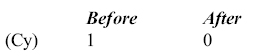
Summary: CMC (1 byte; CMC; 1 opcode)
8.5.2 INSTRUCTION TYPE STC
STC stands for ‘SeT the Carry flag’. It sets the cy flag to the 1 state, immaterial of its earlier value. The result of execution of this instruction is shown below with examples.
Example 1
![]()
![]()
Summary: STC (1 bytes; STC; 1 opcode)
8.6 INSTRUCTIONS TO PERFORM COMPARE OPERATION
A compare instruction compares two operands, and affects the status flags values depending on the result of the comparison. In this operation, 8085 imposes the restriction that one of the operands must be in the Accumulator. The other operand can be one of the following.
- –Contents of an 8-bit register;
- –Contents of memory location pointed by HL pair;
- –Eight-bit immediate data.
The compare instruction actually computes the value of the Accumulator contents minus other operand. The original values of the operands are not changed. The result is stored in a register that is not accessible to the programmer. Based on the result, all the flags are affected.
It is similar to comparing the heights of two people person1 and person2. After the comparison, the heights remain unaltered. But, we would have come to one of the following conclusions.
- Both are of same height;
- Person_1 is taller;
- Person_1 is shorter.
8.6.1 INSTRUCTION TYPE CMP R
CMP is a mnemonic that stands for ‘CoMPare Accumulator’ and ‘R’ stands for any of the following registers, or memory location M pointed by HL pair.
R = A, B, C, D, E, H, L, or M
This instruction is used to compare contents of the Accumulator with R. The result of compare operation will be stored in the Temp register. Temp is an internal register that is not accessible to the programmer. As R can have any of the eight values, there are eight opcodes for this type of instruction. It occupies only 1 byte in memory. ‘CMP E’ is an example instruction of this type. It is a 1-byte instruction. The result of execution of this instruction is shown below with examples.
Example 1


Example 3

Example 4

Example 5

Summary: CMP R (1 byte; CMP E; 8 opcodes)
8.6.2 INSTRUCTION TYPE CPI d8
CPI is a mnemonic that stands for ‘ComPare Immediate with Accumulator’ and ‘d8’ stands for any 8-bit data. This instruction is used to compare Accumulator with 8bit immediate data. The result of the comparison will be stored in an internal register not accessible to the programmer. All the flags are affected based on the result. It occupies 2 bytes in memory. ‘CPI F5H’ is an example instruction of this type. It is a 2-byte instruction. The result of execution of this instruction is shown below with an example.

Summary: CPI d8 (2 bytes; CPI F5H; 1 opcode)
8.7 INSTRUCTIONS TO ROTATE ACCUMULATOR
Intel 8085 provides instructions to rotate Accumulator contents left or right. It is to be noted here that rotate operation can be performed only on Accumulator contents. These instructions are explained as follows.
8.7.1 INSTRUCTION TYPE RLC
RLC stands for ‘Rotate Left Accumulator’. It rotates the Accumulator contents to the left by 1-bit position. Fig. 8.1 illustrates this operation.

Fig. 8.1 Rotate left without involving Cy in rotation
As can be seen, after rotate left operation, the bit that moves out from the MS bit position goes to the vacancy created in the LS bit position. Also, Cy flag gets a copy of the bit moved out from the MS bit position. Notice that Cy flag is not involved in the rotation, and it is only 8-bit rotation of accumulator contents. Only Cy flag is affected by this instruction execution.
The instruction is useful in the following ways.
- To check the value of the MS bit of Accumulator, perform rotate left, and note the cy flag value.
- To perform multiplication by 2, rotate the Accumulator to left. It works correctly for unsigned numbers, as long as the MS bit of Accumulator is a 0 before rotation. For multiplication by 2n, perform rotate left n times.
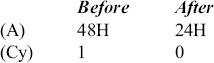
The result of execution of this instruction is shown below with examples.
Example 1

Note that accumulator value is doubled.
Example 2

Note that accumulator value is not doubled in this case because MS bit of accumulator was a 1 before rotation.
8.7.2 INSTRUCTION TYPE RAL
RAL stands for ‘Rotate Accumulator Left involving Cy flag in rotation’. It rotates the Accumulator contents to the left by 1-bit position. Fig. 8.2 illustrates this operation.

Fig. 8.2 Rotate left involving carry in rotation
As can be seen, after rotate left operation, the bit moves out from the MS bit position and goes to the Cy flag, and in the process moves out the earlier carry bit to the vacancy created in the LS bit position. Notice that Cy flag is involved in the rotation, and it is 9-bit rotation of Accumulator and Cy contents. Only Cy flag is affected by this instruction execution.
The instruction is useful in the following ways.
- To check the value of the MS bit of Accumulator, perform rotate left, and note the cy flag value.
- To perform multiplication by 2, rotate the Accumulator to the left. It works correctly for unsigned numbers, as long as the MS bit of Accumulator and Cy flag are 0 before rotation. For multiplication by 2n, perform rotate left n times.
- To introduce a new bit value to the LS bit position, put this bit value in the Cy flag and then execute this instruction.
The result of execution of this instruction is shown below with examples.
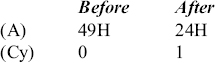
Example 1

Note that Accumulator value is doubled.
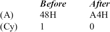
Example 2

Note that Accumulator value is not doubled in this case because MS bit of Accumulator was a 1 before rotation.
Example 3

Note that Accumulator value is not doubled in this case because Cy flag was a 1 before rotation.
8.7.3 INSTRUCTION TYPE RRC
RRC stands for ‘Rotate Right Accumulator’. It rotates the Accumulator contents to the right by 1-bit position. Fig. 8.3 illustrates this operation.
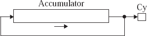
Figure. 8.3 Rotate right without involving carry in rotation
As can be seen, after rotate right operation, the bit moves out from the LS bit position and goes to the vacancy created in the MS bit position. Also, Cy flag gets a copy of the bit moved out from the LS bit position. Notice that the Cy flag is not involved in the rotation, and it is only 8-bit rotation of Accumulator contents. Only Cy flag is affected by this instruction execution.
The instruction is useful in the following ways.
- To check the value of the LS bit of Accumulator, perform rotate right, and note the cy flag value.
- To perform division by 2, rotate the Accumulator to the right. It works correctly for unsigned numbers, as long as the LS bit of Accumulator is a 0 before rotation. For division by 2n, perform rotate right n times.
The result of execution of this instruction is shown below with examples.
Example 1
Note that Accumulator value is halved.
Example 2

Note that Accumulator value is not halved in this case because LS bit of accumulator was a 1 before rotation.
8.7.4 INSTRUCTION TYPE RAR
RAR stands for ‘Rotate Accumulator Right involving Cy flag in rotation’. It rotates the Accumulator contents to the right by 1-bit position. Fig. 8.4 illustrates this operation.
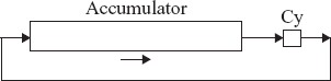
Figure. 8.4 Rotate right involving carry in rotation
As can be seen, after rotate right operation, the bit moves out from the LS bit position and goes to the Cy flag, and in the process moves out the earlier carry bit to the vacancy created in the MS bit position. Notice that Cy flag is involved in the rotation, and it is 9-bit rotation of Accumulator and Cy contents. Only Cy flag is affected by this instruction execution.
The instruction is useful in the following ways.
- To check the value of the LS bit of Accumulator, perform rotate right, and note the cy flag value.
- To perform division by 2, rotate the Accumulator to the right. It works correctly for unsigned numbers, as long as the LS bit of Accumulator and Cy flag are 0 before rotation. For division by 2n, perform rotate right n times.
- To introduce a new bit value to the MS bit position, put this bit value in the Cy flag and then execute this instruction.
The result of execution of this instruction is shown below with examples.
Example 1

Note that Accumulator value is halved.
Example 2
Note that Accumulator value is not halved in this case because LS bit of Accumulator was a 1 before rotation.
Example 3
Note that Accumulator value is not halved in this case because Cy flag was a 1 before rotation.
- Write an 8085 assembly language program, which takes the data from memory location X, and sets to 1 all the odd numbered bits of this byte, and stores the result at memory location Y.
- Write an 8085 assembly language program, which takes the data from memory location X, and resets to 0 all the even numbered bits of this byte, and stores the result at memory location Y.
- Write an 8085 assembly language program that takes the data from memory location X, and complements the 4 bits in the middle of this byte, and stores the result at memory location Y.
- Write an 8085 assembly language program, which takes the data from memory location X, and sets to 1 the MS 2 bits, complements the 4 bits in the middle of this byte, and resets to 0 the LS 2 bits, and stores the result at memory location Y.
- Write an 8085 assembly language program, which takes the data from memory location X, and multiplies this byte by 4, and stores the result at memory location Y.
- Write an 8085 assembly language program, which takes the data from memory location X, and divides this byte by 8, and stores the result at memory location Y.
- Write an 8085 assembly language program, which takes the data from memory location X, and multiplies this byte by 10, and stores the result at memory location Y.
- Assume that before the execution of any instruction we have (A) = 65H, (B) = B2H, (H) = F9H, (L) = 50H, Cy flag = 1, and content of memory location F950H is 38H. What is the value of A register and value of different flags after the execution of each of the following.
- CMP B
- CMP M
- CPI 55H
- RAL
- RRC
- CMA
- CMC
- Distinguish between the following pairs of instructions.
- RAL and RLC
- RRC and RLC
- CMA and CMC
- XRA M and ORA M
- Explain the working of CMP instruction with examples.