
9
NOP and Stack Group of Instructions
![]() Stack and the stack pointer
Stack and the stack pointer
![]() Reading from the stack
Reading from the stack
![]() Writing to the stack
Writing to the stack
![]() Instruction type POP rp
Instruction type POP rp
![]() Instruction type PUSH rp
Instruction type PUSH rp
![]() Instruction type LXI SP, d16
Instruction type LXI SP, d16
![]() Instruction type SPHL
Instruction type SPHL
![]() Instruction type XTHL
Instruction type XTHL
![]() Instruction type INX SP
Instruction type INX SP
![]() Instruction type DCX SP
Instruction type DCX SP
![]() Instruction type DAD SP
Instruction type DAD SP
![]() Instruction type NOP
Instruction type NOP
![]() Questions
Questions
A total of nine instruction types covering 15 instructions will be explained in this chapter.
The NOP and stack group of instructions are discussed in depth in this chapter. In the first half, the role of the stack pointer (SP) is explained and the various instruction types are dealt with in the remaining part of the chapter.
 9.1 STACK AND THE STACK POINTER
Stack is a LIFO (last in, first out) data structure implemented in the RAM area and is used to store addresses and data, when the microprocessor branches to a subroutine. Subroutines are discussed in the next chapter.
In the programmer‘s view of 8085, only the general purpose registers A, B, C, D, E, H, and L, and the Flags registers were discussed so far. But in the complete programmer’s view of 8085, there are two more special purpose registers, each of 16-bit width. They are the stack pointer, SP, and the program counter, PC. The role of PC will be explained in the next chapter. The complete programmer's view of 8085 is shown in Fig. 9.1.

Fig. 9.1 Programmer's view of 8085
SP is a special purpose 16-bit register. It contains a memory address. Suppose SP contents are FC78H, then the 8085 interprets it as follows.
Memory locations FC78H, FC79H, ..., FFFFH are having useful information. In other words, these locations are treated as filled locations. Memory locations FC77H, FC76H, ..., 0000H are not having any useful information. In other words, these locations are treated as empty locations.
Thus, the contents of SP specify the top most useful location in the stack. In other words, it indicates the memory location with the smallest address having useful information. This is pictorially represented in Fig. 9.2.

Fig. 9.2 Interpretation of SP contents
9.1.1 READING FROM THE STACK
Let us say SP contents are FC78H, and we want to read information from a stack location. In this case, we are not interested in reading from a location whose address is less than the memory address present in SP. This is because 8085 interprets them as useless information. For example, there is no point in reading useless information from memory location FC75H.
Right now, memory locations FC78H, FC79H, ..., FFFFH are all interpreted by 8085 to have useful information. Then, which one of these useful information to read? The 8085 reads from the top of the stack of useful information. The 8085 is designed to read always 2 bytes useful information from the top of stack. As such, in this case it reads from locations FC78H and FC79H. In 8085, this information, which is read can only be loaded into a register pair. This operation of loading a register pair by reading information from the stack top is called a POP operation.
Suppose we load register pair BC when SP contents was FC78H. Then, information from memory locations FC78H and FC79H are copied to BC pair. But after this pop operation, the contents of FC78H and FC79H are treated as useless by the 8085. This is because, a copy is there in the register pair BC anyway! Thus only FC7AH, FC7BH, ..., FFFFH are useful locations. To indicate this, the SP contents are changed to FC7AH. This is done automatically by 8085 by incrementing SP contents by 2.
9.1.2 WRITING TO THE STACK
Let us say SP contents are FC7AH, and we want to write information to a stack location. In this case, we are not interested in writing to a location whose address is equal or greater than the memory address present in SP. This is because the 8085 interprets them as having useful information, which should not be destroyed! For example, there is no point in overwriting and destroying useful information at memory location FD7AH. We should be writing into a location where there is presently useless information, and make it useful!
Right now, memory locations FC79H, FC78H, ..., 0000H are all interpreted by 8085 to have useless information. Then, which one of these useless locations to overwrite? The 8085 writes above the top of the stack of useful information. The 8085 is designed to write always into two locations of useless information just above the top of stack. As such, in this case it writes to locations FC79H and FC78H. In 8085, this information, which is written can only be coming from a register pair. This operation of storing a register pair by writing information above the stack top is called a PUSH operation.
Suppose we store register pair BC when SP contents were FC7AH, then, information from BC pair is stored in memory locations FC79H and FC78H. But after this push operation, the contents of FC79H and FC78H are treated as useful by the 8085. This is because nobody stores useless information! Thus FC78H, FC79H, ..., FFFFH are all useful locations. To indicate this, the SP contents are changed to FC78H. This is done automatically by 8085 by decrementing SP contents by 2.
9.2 INSTRUCTION TYPE POP rp
This instruction loads register pair rp by popping out 2 bytes from the top of the stack. In previous chapters, ‘rp’ stood for any of the register pairs BC, DE, or HL. But as per the programmer's view in Fig. 9.1, we can treat combination of Accumulator and flags as one more register pair. This pair is generally called PSW, which stands for ‘processor status word’. In the PSW, Accumulator is the MS byte, and Flags register is the LS byte.
Two bits are used in an opcode to specify a register pair. Thus actually four register pairs can be specified using 2-bit code for ‘rp’. In fact, even SP can be treated as a register pair. Thus in all there are five register pairs. One may think that to specify one of them, 3 bits are needed. But 8085 opcodes use only 2 bits to specify a register pair as shown below. The ‘rp’ code of 11 specifies either SP or PSW, but not both. For example, in POP rp instruction, rp can be BC, DE, HL, or PSW. There is no instruction like POP SP. Similarly, in LXI rp instruction, rp can be BC, DE, HL, or SP. There is no instruction like LXI PSW.
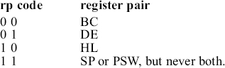
Thus, in POP rp instruction ‘rp’ stands for one of the following register pairs.
rp = BC, DE, HL, or PSW
As rp can have any of the four values, there are four opcodes for this type of instruction. It occupies only 1 byte in memory. ‘POP PSW’ is an example instruction of this type. It is an 1-byte instruction. The result of execution of this instruction is shown below with an example.

Note that POP PSW instruction is useful in loading the flags register with any desired value. Suppose it is desired to load flags register with the value 66H, the following instructions have to be executed.

Summary: POP rp (1 byte; POP PSW; 4 opcodes)
9.3 INSTRUCTION TYPE PUSH rp
This instruction stores contents of register pair rp by pushing it into two locations above the top of the stack. rp stands for one of the following register pairs.
rp = BC, DE, HL, or PSW
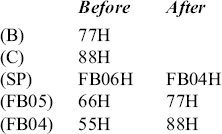
As rp can have any of the four values, there are four opcodes for this type of instruction. It occupies only 1 byte in memory. ‘PUSH B’ is an example instruction of this type. It is a 1-byte instruction. The result of execution of this instruction is shown below with an example.
Summary: PUSH rp (1 byte; PUSH B; 4 opcodes)
Suppose we execute the following instructions, with SP contents as FB08H to start with.

Then the stack contents will be as shown overleaf after the execution of the previously mentioned instructions.

The SP contents are changed to FB00H. As we start pushing, the information starts getting stacked one above the other. This justifies the name ‘stack’ for this data structure in RAM. Notice that the stack has to be implemented in RAM, as we need to perform write operation on the stack, called the PUSH operation.
In the earlier example, PSW contents were pushed above the stack top in the end. Now if we perform pop operation, this information comes out first. Thus, a stack is a LIFO (Last In First Out) data structure. Of course, it can also be equivalently termed as first in last out (FILO).
In summary, SP is a 16-bit register inside 8085. Its contents specify the topmost filled memory location in the stack. Stack is a LIFO data structure implemented in RAM. In push or pop operations the data transfer is between a register pair and the stack.
The stack grows towards the address 0000H, as push operations are performed. The SP content is decremented by two for every push operation. It shrinks towards the address FFFFH, as pop operations are performed. The SP contents are incremented by two for every pop operation.
SP is generally loaded with the highest RAM address +1. For example, if we have RAM from C000H to C7FFH, then SP is loaded with C800H at the beginning of the user program. The program is generally loaded on a kit starting from the lowest RAM address. This allows the user program to expand towards higher addresses and the stack to grow towards lower addresses, without overlapping.
9.4 INSTRUCTION TYPE LXI SP, d16
Let us say, SP contents is FC00H and it is desired to pop contents of FC06H and FC07H to BC register pair. One way of achieving this objective is by executing the following sequence of instructions.
POP B; pop contents of FC00 and FC01 to BC pair;
POP B; pop contents of FC02 and FC03 to BC pair;
POP B; pop contents of FC04 and FC05 to BC pair;
POP B; finally pop contents of FC06 and FC07 to BC pair.
However, this is a laborious process. Loading SP with FC06H, and then popping to BC pair can achieve the same very efficiently. When SP is loaded with FC06H, 8085 interprets that FC06H, FC07H, ..., FFFFH are all filled locations. Then POP B instruction execution results in popping contents of FC06H and FC07H to BC pair.
LXI SP, d16 instruction is a special case of LXI rp, d16 which was discussed in the chapter on data transfer group of instructions. Thus LXI SP instruction is used to load 16-bit immediate data to the SP. It occupies 3 bytes in memory. ‘LXI SP FC06H’ is an example instruction of this type. It is a 3-byte instruction. The result of execution of this instruction is shown in the following example.
Summary: LXI SP d16 (3 bytes; LXI SP, FC06H; 1 opcode)
9.5 INSTRUCTION TYPE SPHL
This instruction loads the stack pointer with the contents of register pair HL. It is an indirect way of loading the stack pointer, and as such, it is not quite commonly used. It occupies only 1 byte in memory, compared to LXI SP instruction, which is 3 bytes long. Because of this advantage, SPHL can be useful when SP is required to be initialized to a specific value a number of times in a program.
The result of execution of this instruction is shown below with an example.
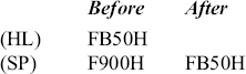
Summary: SPHL (1 byte; SPHL; 1 opcode)
9.6 INSTRUCTION TYPE XTHL
XTHL is a mnemonic that stands for ‘eXchange Top of stack with HL’. This instruction exchanges the contents of the top two locations of the stack with the contents of register pair HL. Note that it is not exchange of SP with HL.
It occupies only 1 byte in memory. The result of execution of this instruction is shown below with an example. Note that SP contents remain unchanged. It is neither decremented nor incremented.
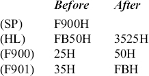
Summary: XTHL (1 byte; XTHL; 1 opcode)
9.7 INSTRUCTION TYPE INX SP
INX SP instruction is a special case of INX rp that was discussed in the chapter on arithmetic group of instructions. Thus INX SP instruction is used to increment the SP contents by 1. It occupies only 1 byte in memory. The result of execution of this is shown in the following example.
Summary: INX SP (1 byte; INX SP; 1 opcode)
9.8 INSTRUCTION TYPE DCX SP
DCX SP instruction is a special case of DCX rp that was discussed in the chapter on arithmetic group of instructions. Thus DCX SP instruction is used to decrement the SP contents by 1. It occupies only 1 byte in memory. The result of execution of this instruction is shown below with an example.
![]()
Summary: DCX SP (1 byte; DCX SP; 1 opcode)
9.9 INSTRUCTION TYPE DAD SP
DAD SP instruction is a special case of DAD rp, which was discussed in the chapter on arithmetic group of instructions. Thus DAD SP instruction is used to add SP contents to HL contents, and store the result in HL. It occupies only 1 byte in memory. The result of execution of this instruction is shown below with an example. Only carry flag is affected depending on the result.
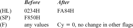
Summary: DAD SP (1 byte; DAD SP; 1 opcode)
9.10 INSTRUCTION TYPE NOP
NOP is an instruction that cannot be classified under any group discussed so far. For convenience, we discuss this instruction in this chapter.
NOP is a mnemonic that stands for ‘No OPeration’. This instruction does not do anything! Still, it is quite useful. It occupies only 1 byte in memory. It has the opcode 00H. It is useful in the following cases.
1. NOP instruction is very useful for generating small-time delays of the order of a few microseconds. Let us say, the 8085 has to send information to two peripherals with a gap of approximately 4 μs. In such a case, after sending information to the first peripheral, it has to wait for 4 μs. This is where an NOP instruction is very useful. Every instruction needs a certain time for instruction fetch and execution. These details are provided in a later chapter on 8085 architecture. NOP instruction uses up about 1.3 μs for the instruction fetch and execution. If there are three NOP instructions, then about 4 μs delay is generated. After these NOP instructions, information can be sent to the second peripheral.
2. NOP instruction is very useful when we are required to delete a few instructions in our program. Let us say we have a long program as shown in the following.

When the program is executed, let us say we do not get the desired result, because the program is wrong. Then we go about debugging the program in single step mode. Let us say, we come to the conclusion that the instruction ‘MOV D, A’ at location F804H should be removed. If we remove the instruction ‘MOV D, A’, then the program portion from memory location F805H to FD56H should be moved up by one position. This amounts to almost rewriting the whole program, as the error has occurred in the beginning of the program. Anyway, we do not have to lose heart, as NOP instruction is there to our rescue. We just have to replace ‘MOV D, A’ with NOP instruction! Then there is no need for moving up by one position the program portion from F805H to FD56H.
3. NOP instruction is very useful when we are required to insert a few instructions in our program. Let us say we have a long program as shown in the following.
When the program is executed, let us say we do not get the desired result, because the program is wrong. Then we go about debugging the program in single step mode. Let us say, we come to the conclusion that in between MOV B, A and MOV D, A there should have been MOV C, A also. If we insert the instruction ‘MOV C, A’ at F804H, then the original program portion from memory location F804H to FD56H should be moved down by one position. This amounts to almost rewriting the whole program, as the error has occurred in the beginning of the program. Anyway, we do not have to lose heart, if we have NOP instructions at several places in our program. Suppose we have a NOP instruction at F811H, then we have to move down only a small portion of the program from F804H to F810H by one location. Now the earlier NOP instruction is replaced with ADD E.
Thus, it is a good programming practice to have a few NOP instructions in the program at regular intervals, especially during program development. Alternatively, the user can make use of ‘insert’ and ‘delete’ keys provided on the kit, which help in inserting new instructions to the program, or delete existing instructions.
Summary: NOP (1 byte; NOP; 1 opcode) 1.
- Differentiate between stack pointer and stack.
- Why the stack should not be implemented in ROM?
- Explain with examples, the two basic operations performed on stack contents.
- What is PSW? Write a 8085 assembly language program to exchange contents of accumulator and flag registers.
- Write a 8085 assembly language program to exchange contents of PSW and HL.
- Distinguish between the following pairs of instructions.
- XTHL and SPHL,
- LXI SP, d16 and SPHL.
- Explain the utility of NOP instruction.