
14
Simple Assembly Language Programs
![]() Exchange 10 bytes
Exchange 10 bytes
![]() Entry of data and code
Entry of data and code
![]() Executing the program and checking result
Executing the program and checking result
![]() Add two multi-byte numbers
Add two multi-byte numbers
![]() Add two multi-byte BCD numbers
Add two multi-byte BCD numbers
![]() Block movement without overlap
Block movement without overlap
![]() Block movement with overlap
Block movement with overlap
![]() Approach methodology
Approach methodology
![]() Add N numbers, of size 8 bits
Add N numbers, of size 8 bits
![]() Monitor routines
Monitor routines
![]() Check the fourth bit of a byte
Check the fourth bit of a byte
![]() Subtract two multi-byte numbers
Subtract two multi-byte numbers
![]() Multiply two numbers of size 8 bits
Multiply two numbers of size 8 bits
![]() Trace of the programm
Trace of the programm
![]() Divide a 16-bit number by an 8-bit number
Divide a 16-bit number by an 8-bit number
![]() Questions
Questions
This chapter deals with various assembly language programs, such as programs to exchange 10 bytes, to add/subtract two multi-byte numbers, to add two multi-byte BCD numbers, to multiply two 8-bit numbers, and to divide a 16-bit number by an 8-bit number. These assembly language -programs will be manually translated using the opcode information provided in the appendix.
 14.1 EXCHANGE 10 BYTES
Write an 8085 assembly language program to exchange 10 bytes of data stored from location X with 10 bytes of data stored from location Y.
Flowchart for the program
Flowchart for solving the problem is shown in Fig. 14.1.

Fig. 14.1 Flowchart for exchange of 10 bytes.
Program to exchange 10 bytes
; FILE NAME C:ALSXCHG.ASM
 ; Suppose we want to make some changes to the source file. If a print out
;of the program informs us about the file name for the program on the disk,
;it becomes easy to search the file and make modifications to the program.

   ;8085 ALP TO INTERCHANGE 10 BYTES OF DATA STORED FROM
   ;LOCATION X WITH 10 BYTES OF DATA STORED FROM LOCATION Y

   ORG C100H
  X: DB 11H, 22H, 33H, 44H, 55H, 66H, 77H, 88H, 99H, AAH

   ORG C200H
  Y: DB 01H, 02H, 03H, 04H, 05H, 06H, 07H, 08H, 09H, 0AH

;For manual translation store 11H,22H etc starting at location C100H.
;Similarly, the following program after manual translation should be stored
;from location C000H. ORG, DB are Assembler directives and are explained in
;detail in the next chapter.
   ORG C000H

   LXI D, X ; Load DE with C100H (address X)
   LXI H, Y ; Load HL with C200H (address Y)
   MVI C, 0AH; Load C with 0AH (C used as down counter)

   ; The instructions from here to JNZ LOOP perform exchange
   ; of bytes at memory locations pointed by DE and HL

LOOP:    LDAX D     ; Load A from memory pointed by DE
         MOV B, M   ; Load B from memory pointed by HL
         MOV M, A   ; Store A in memory pointed by HL
         MOV A, B
         STAX D     ;;Store B in memory pointed by DE
;In the convention followed in this book, a single ‘;’ after an instruction ;provides comments for the instruction. If there are N number of ‘;’ after an
;instruction, it provides comments for N instructions preceding the N number
;of semicolons.
       INX D
       INX H     ;;Increment address pointers DE and HL
       DCR C     ; Decrement C
       JNZ LOOP  ; If not zero jump to LOOP
       HLT       ; Stop when all the bytes are exchanged
14.1.1 ENTRY OF DATA AND CODE
The data and code to be entered on the kit for the previous program is shown in the following.
Entry of data: In the previous program, X is symbolic memory location C100H, and data is stored from C100H as follows.
| Address | Data |
| C100 | 11H |
| C101 | 22H |
| C102 | 33H |
| C103 | 44H |
| C104 | 55H |
| C105 | 66H |
| C106 | 77H |
| C107 | 88H |
| C108 | 99H |
| C109 | AAH |
Similarly, Y is symbolic memory location C200H, and data is stored from C200H as follows.
| Address | Data |
| C200 | 01H |
| C201 | 02H |
| C202 | 03H |
| C203 | 04H |
| C204 | 05H |
| C205 | 06H |
| C206 | 07H |
| C207 | 08H |
| C208 | 09H |
| C209 | 0AH |
Entry of code: In the previous program, code is stored from C000Has follows with addresses and code in hexadecimal.
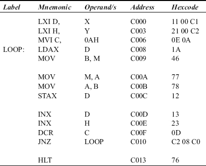
It can be noticed from this that LOOP is a symbolic memory location, which is actually memory location with address C008H. Thus, JNZ LOOP is manually translated as C2 08 C0, where C2 is code for JNZ and 08 C0 is C008H stored in memory in byte reversal form.
14.1.2 EXECUTING THE PROGRAM AND CHECKING RESULT
When the program is run by typing on the kit ‘Go C 0 0 0 Exec’, we see the display ‘E’ in the address field of the display. At this point the 8085 has halted processing because of the HLT instruction execution. To check the results after program execution, we have to first of all reset the 8085 by typing ‘Reset’ key. Then the monitor program gains control over the kit, and we can see the contents of C100 to C109, and C200 to C209.
Alternatively, we can end the program with ‘RST 1’ (code 5 CF) instruction instead of HLT instruction, when we are using ALS kit. Execution of RST 1 instruction on ALS kit results in the monitor program gaining control over the kit. So we are now in a position to see the results in memory. Thus we can avoid the step of resetting the 8085. The reader must note that with other kits he may have to terminate the program with say, RST 5, to transfer control to the monitor program. Refer to kit manual to obtain correct information.
14.2 ADD TWO MULTI-BYTE NUMBERS
Write a 8085 assembly language program to add two multi-byte numbers. The numbers are stored from locations X and Y in byte reversal form. The size in bytes of the multi-byte numbers is given in the location, SIZE. The result is to be stored in location Z, in byte reversal form, using 1 byte more than the size of multi-byte numbers.
Flowchart for the program
Flowchart for solving the problem is shown in Fig. 14.2.
Program to add two multi-byte numbers
;FILE NAME C:ALSADLRGBYT.ASM

;8085 ALP TO ADD 2 MULTI BYTE NUMBERS.
;THE NUMBERS ARE STORED FROM LOCATIONS X AND Y.
;AT X AND Y, THE LS BYTE OF MULTI BYTE NUMBER IS PRESENT.
;THE SIZE IN BYTES OF THE MULTI BYTE NUMBERS IS GIVEN IN LOCATION SIZE
;THE RESULT IS STORED FROM LOCATION Z, USING SIZE11 BYTES.

             ORG C050H
SIZE         DB 03H

             ORG C100H
X:           DB 12H, 34H, 56H

             ORG C200H
Y:           DB 56H, 78H, ACH

             ORG C000H
Z:           EQU C300H; Z is equal to C300H

;Thus wherever we come across Z, we replace it with C300H
      LXI B, X ;Load BC with C100H (address X)
      LXI H, Y ;Load HL with C200H (address Y)
      LXI D, Z ;Load DE with C300H (address Z)
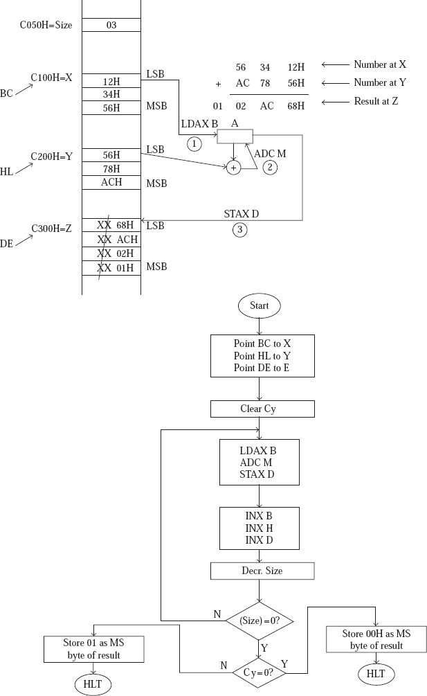
Fig. 14.2 Flowchart for adding two multi-byte numbers
STC
           CMC   ;;Reset Cy flag to 0

;The instructions from here to JNZ LOOP perform addition with carry of the
;bytes pointed by BC and HL, and stores the result at memory pointed by
;DE. BC, HL, and DE pointers are incremented, and contents of location SIZE
;is decremented.
  LOOP:    LDAX B   ;Load A from memory pointed by BC
           ADC M    ;Add to A with Cy memory contents pointed by HL
           STAX D   ;Store result in memory pointed by DE

           INX B
           INX H
           INX D    ;;;Increment the pointers BC, HL, and DE

           LDA SIZE
           DCR A
           STA SIZE ;;;Decrement contents of memory location SIZE
           JNZ LOOp ;If result of decrement is non zero jump to LOOP
;When we are out of this loop A contents is 00H.
           JNC SKIP ;Jump to SKIP if Cy 5 0
           INR A

SKIP:      STAX D ;; Store 00 or 01 in memory pointed by DE, based on Cy

           HLT     ;Alternatively terminate the program with RST 1
Notice that INX B, INX H, and INX D instructions do not affect any flags. Also note that DCR A instruction affects all flags except Cy. Thus, when we execute JNC SKIP later on in the program, the jump takes place based only on the value of the Cy flag after execution of the ADC M instruction. In fact, in view of such requirements only, the designers of 8085 have implemented INX instructions such that flags are not affected, and DCR/INR instructions such that Cy flag is not affected.
In this program, we faced the problem of shortage of registers, although seven registers are provided in 8085. So we had to make use of memory location SIZE. In Motorola 6800, with only two registers inside, we do not face any problem! This is because of the powerful indexed addressing mode provided in 6800. See chapter on 6800 microprocessor for details.
14.3 ADD TWO MULTI-BYTE BCD NUMBERS
Write an 8085 assembly language program to add two multi-byte BCD numbers. The numbers are stored in locations X and Y in byte reversal form. The size in bytes of the multi-byte numbers is given in the location, SIZE. The result is to be stored in location Z, in byte reversal form, using 1 byte more than the size of multi-byte numbers.
Flowchart for the program
Flowchart for solving the problem is shown in Fig. 14.3.
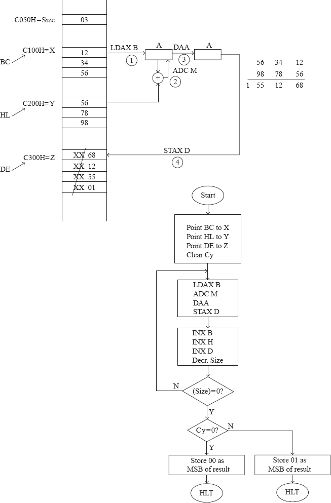
Fig. 14.3 Flowchart for adding two multi-byte BCD numbers
Program to add two multi-byte BCD numbers
;FILE NAME C:ALSADLRGBCD.ASM
;8085 ALP TO ADD 2 MULTI BYTE BCD NUMBERS.
;THE NUMBERS ARE STORED FROM LOCATIONS X AND Y.
;AT X AND Y, THE LS BYTE OF MULTI BYTE NUMBER IS PRESENT.
;THE SIZE IN BYTES OF THE MULTI BYTE NUMBERS IS GIVEN IN LOCATION SIZE
;THE RESULT IS STORED FROM LOCATION Z, USING SIZE11 BYTES.
             ORG C050H

SIZE    DB 03H
             ORG C100H

X:           DB 12H, 34H, 56H
             ORG C200H

Y:           DB 56H, 78H, 98H
             ORG C000H

Z:           EQU C300H

        LXI B, X ;Load BC with C100H (address X)
        LXI H, Y ;Load HL with C200H (address Y)
        LXI D, Z ;Load DE with C300H (address Z)

        STC
        CMC      ;;Clear Carry flag

;The instructions from here to JNZ LOOP perform decimal addition with carry             ;of a byte pointed by BC with a byte pointed by HL. The result is stored in             ;memory pointed by DE. BC, HL, and DE pointers are incremented, and contents
;of location SIZE is decremented.
  LOOP:      LDAX B  ;Load A from memory pointed by BC
             ADC M   ;Add with Cy memory contents pointed by HL
             DAA     ;Perform decimal adjustment
             STAX D  ;Store result in memory pointed by DE

             INX B
             INX H
             INX D   ;;;Increment the pointers BC, HL, and DE by 1

             LDA SIZE
             DCR A
             STA SIZE ;;;Decrement contents of location SIZE
             JNZ LOOP ;If result of decrement is nonzero jump to LOOP
;When we are out of this loop, contents of A will be 00H
             JNC SKIP
             INR A

SKIP:        STAX D ;;;Store 00 or 01 in memory pointed by DE based on Cy

             HLT     ;Alternatively terminate with RST 1
14.4 BLOCK MOVEMENT WITHOUT OVERLAP
Write an 8085 assembly language program to perform block movement. The blocks are assumed to be non-overlapping. The block starting at location X is to be moved to the block starting at Y. The block size is provided in the location, SIZE.
Flowchart for the program
Flowchart for solving the problem is shown in Fig. 14.4.
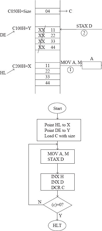
Fig. 14.4 Performing block movement without overlap
Program to perform block movement without overlap
;FILE NAME C:ALSBLKMOV.ASM
;8085 ALP TO PERFORM BLOCK MOVEMENT OF A BLOCK STARTING
;FROM LOCATION X, TO THE BLOCK STARTING FROM LOCATION Y.
;SIZE OF THE BLOCK PROVIDED IN LOCATION SIZE.

   ;IT WORKS ONLY WHEN
       ;a. THERE IS NO OVERLAP OF BLOCKS
       ;b. THERE IS OVERLAP WITH ADDRESS X LARGER THAN ADDRESS Y

             ORG C050H
SIZE:        DB 04H

             ORG C200H
X:           DB 11H, 22H, 33H, 44H

             ORG C000H
Y:           EQU C100H

             LDA SIZE
             MOV C, A ;Load C with contents of location SIZE

             LXI H, X ;Load HL with C200H (address of X)
             LXI D, Y ;Load DE with C100H (address of Y)
;The instructions from here to JNZ LOOP perform movement of the byte pointed
;by HL to memory pointed by DE. HL and DE pointers are incremented. Counter C
;is decremented.
   LOOP:      MOV A, M
              STAX D   ;;Move the byte pointed by HL to memory pointed by DE

              INX H
              INX D
              DCR C    ;;;Increment the pointers HL and DE. Decrement C.
              JNZ LOOP   ;Jump to LOOP if result after decrement is nonzero

              HLT        ;Alternatively terminate with RST 1
14.5 BLOCK MOVEMENT WITH OVERLAP
Write an 8085 assembly language program to perform block movement. The block starting at location X is to be moved to the block starting at Y. The block size is provided in the location, SIZE. The program should work irrespective of overlap of blocks or not.
14.5.1 APPROACH METHODOLOGY
In this program we have used C register as a down counter to store source block on the stack. We have used B register as a down counter to pop out the source block on the stack to the destination block. The program works even if there is overlap of blocks.
We load B and C registers with the size of the block. Then load HL and DE with the starting address of source block and destination block, respectively.
Then the byte pointed by HL is moved to A. It is then pushed above the stack top. Even flags register is pushed on the stack top because of the execution of PUSH PSW. But we do not care about it. Incrementing the pointers HL and DE, and decrementing the counter C is done. If C contents are not yet zero, we repeat the operations indicated in this paragraph.
Thus when we come out of the loop, the source block is stored on the stack. Of course, the stack size would have become twice the block size, because of pushing flags register also every time. The DE register will now be pointing to the next location after the last location in the destination block.
Now decrement pointer DE. Pop the stack top to A and flags. Store A value in memory pointed by DE. Just ignore the flags value popped out. Now decrement the counter B. If B contents are not yet zero, we repeat the operations indicated in this paragraph.
Halt when we come out of this loop, as the block movement is over.
Flowchart for the program
Flowchart and the method for solving the problem is shown in Fig. 14.5.
Program to perform block movement even with overlap
;FILE NAME C:ALSBLKMOV2.ASM
;8085 ALP TO PERFORM BLOCK MOVEMENT OF A BLOCK STARTING
;FROM LOCATION X, TO THE BLOCK STARTING FROM LOCATION Y.

;PROGRAM WORKS WHETHER THERE IS OVERLAP OR NOT OF THE BLOCKS.

            ORG C050H
SIZE:       DB  04H

            ORG C100H
X:          DB 11H, 22H, 33H, 44H

            ORG C102H
Y:          DB 33H, 44H, 55H, 66H

            ORG C000H
            LDA SIZE
            MOV B, A
            MOV C, A ;;;Load B and C registers with block size

            LXI H, X ;Load HL with C100H (address X)
            LXI D, Y ;Load DE with C102H (address Y)

      ;For the block size of 4, there will be overlap of blocks

;The instructions from here to JNZ LOOP1 perform pushing the byte point                 ;ed by

;HL to the stack, and then incrementing the pointers HL and DE, and
;decrementing the counter C.
   LOOP1:   MOV A,M
            PUSH PSW ;;Push the byte pointed by HL on to the stack
                      ;Flags is also pushed on stack, but we don't care

            INX H
            INX D    ;;Increment the pointers HL and DE
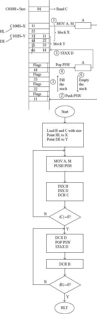
Fig. 14.5 Performing block movement even with overlap
DCR C       ;Decrement C
            JNZ LOOP1   ;Jump to LOOP1 if C is not decremented to 00H
   :When are out of this loop, DE will be pointing to the next location
  ;after end of destination block
;The instructions from here to JNZ LOOP2 perform decrementing the pointer DE
;and then popping a byte from the stack and storing in memory pointed by DE.
;Finally decrements the counter B.
   LOOP2:     DCX D      ;Decrement the pointer DE
              POP PSW
              STAX D     ;;Pop the byte from stack top to memory pointed by DE
              DCR B      ;Decrement B
              JNZ LOOP2  ;Jump to LOOP2 if B is not decremented to 00H
              HLT
14.6 ADD N NUMBERS OF SIZE 8 BITS
Write an 8085 assembly language program to perform addition of N 1-byte numbers. N value is provided in location X. From location X+1, the N numbers are stored. Store the result in location Y and Y+1. Also display the result in the address field.
Flowchart for the program
Flowchart for solving the problem is shown in Fig. 14.6.
Program to add N bytes
;FILE NAME C:ALSADDNBYT.ASM
;8085 ALP TO ADD N ONE BYTE NUMBERS. N IS STORED AT LOCATION X.
;FROM X11, THE NUMBERS ARE STORED. RESULT STORED IN LOCATIONS Y AND Y+1.
;ALSO DISPLAY THE RESULT IN THE ADDRESS FIELD.
           ORG C100H
X:         DB 03H, ECH, DDH, 0EH

           ORG C000H
Y:         EQU C200H
CURAD:     EQU FFF7H ;Applicable only if ALS kit is being used
UPDAD:     EQU 06BCH ;Applicable only if ALS kit is being used

           MVI B, 00H ;Initialise B with 00H.
           LXI H, X
           MOV C, M ;;Load C with number of bytes to be added
           DCR C    ;Decrement C. C now indicates the number of additions
                    ;to be performed
           INX H
           MOV A,M  ;;Load A with the first byte
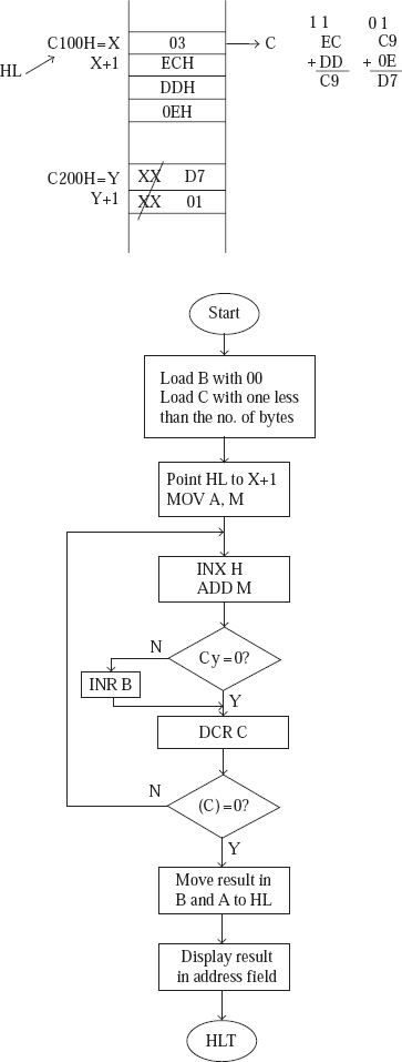
Fig. 14.6 Addition of N 1-byte numbers
;The instructions from here to JNZ AGAIN performs the following. It adds the
;next byte to A. B will be incremented by 1 if there is Carry. Decrements the
;counter C, and if nonzero repeats the operations.
  AGAIN:      INX H
              ADD M           ;;Add to A the next byte

              JNC NOINRB
              INR B           ;;B is incremented by 1 if there is Cy

  NOINRB:     DCR C           ;Decrement C
              JNZ AGAIN       ;If not zero jump to AGAIN

;When we come out of the loop, B will have MS byte of sum and A will have LS
;byte of sum

              MOV H, B
              MOV L, A  ;;Load HL with the sum in B and A registers
              SHLD Y    ;Store the sum in word location Y
              SHLD CURAD
              CALL UPDAD ;;Display the result in address field
              HLT         ;Make sure to terminate with HLT instead of RST 1
In the previous program, suppose we terminate the program with RST 1 instead of HLT. Then the program displays the result in the address field, and the next moment returns control to monitor program, which displays the sign on message. Thus, the user fails to see the result in the address field. If the program is terminated with HLT, the processor halts after the program displays the result in the address field. Thus, the result is displayed till the processor is reset.
14.6.1 MONITOR ROUTINES
Any 8085 microprocessor kit generally provides a number of utility routines, which can be called by the user. These routines form part of the monitor program in the EPROM/ROM of the kit. These -routines simplify program development. As a general rule, the user should save all the registers of interest before calling a monitor routine. The registers should be restored with original values after returning from the monitor routine.
UPDAD routine: In this program, we have used the monitor routine UPDAD, which is used to update the address field on the kit. The routine displays the contents of the word at symbolic location CURAD.
On the ALS kit UPDAD routine is at address 06BCH, and CURAD is word location FFF7H. Thus, if we have 78H in location FFF7H and 56H at location FFF8H, execution of ‘CALL UPDAD’ instruction results in display of ‘5678’ in the address field. CALL UPDAD is coded as CD BC 06.
In addition, if B register content is 00H, there will not be any dot at the end of the address field. If B contents are 01H, a dot will be displayed at the end of the address field.
The contents of the registers A, B, C, D, E, H, L, and flags are all altered on executing CALL UPDAD.
The other common routines like UPDDT, RDKBD are described later.
14.7 CHECK THE FOURTH BIT OF A BYTE
Write an 8085 assembly language program to check whether the fourth bit of a byte at location X is a 0 or a 1. If 0, store 00 at location Y. Else, store FF at Y. Display the number and the result in the address field.
Flowchart for the program
Flowchart for solving the problem is shown in Fig. 14.7.
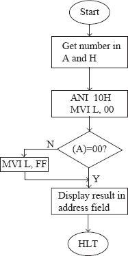
Fig. 14.7 To check the fourth bit of a given byte
Program to check the fourth bit of a given byte
;FILE NAME C:ALSCHEKBIT.ASM
  ;8085 ALP TO CHECK WHETHER THE 4TH BIT OF A BYTE STORED AT
  ;LOCATION X IS 0 OR 1. IF 0, STORE 00 AT LOCATION Y. ELSE, STORE
  ;FF AT Y. DISPLAY THE NUMBER AND THE RESULT IN THE ADDRESS FIELD.
            ORG C100H
X:          DB 35H

            ORG C000H
CURAD:      EQU FFF7H
UPDAD:      EQU 06BCH

            LDA X
            MOV H, A   ;;Load A and H from contents of location X.
            MVI L, 00H ;Load L with 00.
            ANI 10H    ;Reset all bits to 0, except 4th bit.
            JZ OUTZERO ;If result is 00H, jump to OUTZERO.

            MVI L,FFH  ;If result is non zero, load L with FF.
;Thus at this point, L will have 00 or FF depending on bit 4.
OUTZERO:     SHLD CURAD
             CALL UPDAD ;;Display the byte, and 00 or FF, in address field.
             HLT
14.8 SUBTRACT TWO MULTI-BYTE NUMBERS
Write an 8085 assembly language program to perform subtraction of two multi-byte numbers. The number of bytes in these multi-byte numbers is stored in the location, SIZE. The numbers are stored in locations starting from X and Y. The number starting at X is subtracted from the number starting at Y. Result is stored in locations starting from Z.
Flowchart for the program
Flowchart for solving the problem is shown in Fig. 14.8.
Program to subtract two multi-byte numbers
;FILE NAME C:ALSSBLRGBIN.ASM

;8085 ALP TO SUBTRACT TWO MULTI BYTE BINARY NUMBERS. THE NUMBER OF BYTES IN
;THESE MULTI BYTE NUMBERS IS STORED AT LOCATION SIZE. THE NUMBERS ARE STORED
;IN LOCATIONS STARTING FROM X AND Y. THE NUMBER STARTING AT X IS SUBTRACTED
;FROM THE NUMBER STARTING AT Y. RESULT IS STORED IN LOCATIONS STARTING FROM
;Z.

;IF THE NUMBER STARTING AT LOCATION X IS THE LARGER ONE, THE RESULT WILL BE
;IN 2'S COMPLEMENT FORM.

               RG C000H
    SIZE:      EQU C100H
    X:         EQU C200H
    Y:         EQU C300H
    Z:         EQU C400H

               LXI D,Y ;Load DE with C300H (address Y)
               LXI H,X ;Load HL with C200H (address X)
               LXI B,Z ;Load BC with C400H (address Z)

               STC
               CMC     ;;Clear Carry flag
    REP:    LDAX D ;Load A from memory pointed by DE

                SBB M  ;Subtract with borrow memory contents pointed by HL
                STAX B ;Store result in memory pointed by BC

                INX H
                INX D
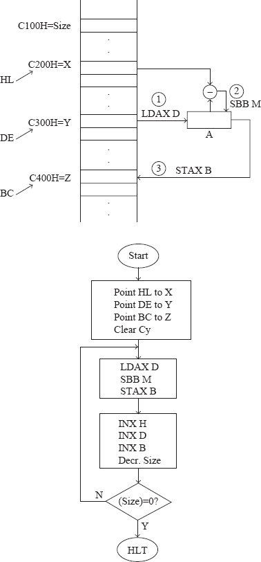
Fig. 14.8 Subtraction of two multi-byte numbers
INX B ;;;Increment the pointers HL, DE, and BC

                LDA SIZE
                DCR A
                STA SIZE

                JNZ REP ;If not zero jump to REP

                HLT
14.9 MULTIPLY TWO NUMBERS OF SIZE 8 BITS
Write an 8085 assembly language program to multiply two 8-bit numbers stored at locations X and Y. Store the 16-bit result in locations Z and Z+1. Also display the result in the address field.
Flowchart for the program
Flowchart for solving the problem is shown in Fig. 14.9.

Fig. 14.9 Multiplication of two 8-bit numbers
Program to multiply two 8-bit numbers
;FILE NAME C:ALSMULT.ASM

;8085 ALP TO MULTIPLY 2 ONE BYTE BINARY NUMBERS STORED AT LOCATIONS X AnD
;Y. DISPLAY THE 16 BIT RESULT IN THE ADDRESS FIELD.

;IT USES REPEATED ADDITION, AND AS SUCH IS NOT AN EFFICIENT METHOD.

            ORG C100H
  X:        DB 05H

            ORG C200H
  Y:        DB 04H
            ORG C000H
  Z:        EQU C300H
  CURAD:    EQU FFF7H
  UPDAD:    EQU 06BCH

            LXI H, X
            MOV E,M
            MVI D,00H  ;;;Load DE with the byte at location X

            LXI H,Y
            MOV A,M    ;;Load A with the number at location Y

            LXI H,0000H;Initialise HL with 0000H

            CPI 00H
            JZ EXIT    ;;If A value is 00H jump to EXIT to display 0000

 AGAIN:     DAD D      ;Add HL and DE contents
            DCR A      ;Decrement A
            JNZ AGAIN  ;If result of decrement is not zero jump to AGAIN
     ;When we are out of this loop, the product will be in HL
 EXIT:      SHLD Z
            SHLD CURAD       ;;HL contents stored in word locations Z and CURAD
            CALL UPDAD       ;Display result in the address field
            HLT              ;Make sure to terminate with HLT instead of RST 1
14.9.1 TRACE OF THE PROGRAM
In a program, knowing the actual values in affected registers and/or memory locations at the end of the execution of every instruction for a given set of sample data is called ‘tracing the program’. Many times, it is easier to understand the working of the program by the trace for the program than by its flowchart or algorithm.
What follows is the trace for multiplication of two 8-bit numbers. The numbers are taken to be 05H and 04H.
Suppose several instructions are executed in a loop, then we indicate the contents of the affected register or memory location for each pass through the loop on a single line separated by ‘|’ character.
For example, in the portion of the trace shown below we go through the loop four times. The values of HL and A at the end of each pass are shown separated by ‘|’. In the third line of the trace portion, J and NJ stand for ‘jump’ and ‘no jump’, respectively.
AGAIN:           DAD D            ;HL = 0005H| 000AH| 000FH| 0014H
                 DCR A            ;A  =   03H| 02H  | 01H  | 00H
                 JNZ AGAIN                ;J |    J |   J  |   NJ
This convention results in easy tracing of the program as shown below.
;FILE NAME C:ALSMULT.ASM
;8085 ALP TO MULTIPLY 2 ONE BYTE BINARY NUMBERS STORED AT LOCATIONS X
;AND Y. DISPLAY THE 16 BIT RESULT IN THE ADDRESS FIELD.

;IT USES REPEATED ADDITION, AND AS SUCH IS NOT AN EFFICIENT METHOD.

          ORG C100H
X:        DB 05H

          ORG C200H
Y:        DB 04H

          ORG C000H
Z:        EQU C300H
CURAD:    EQU FFF7H
UPDAD:    EQU 06BCH

          LXI H, X      ; HL = C100H
          MOV E, M      ; E  = 05H
          MVI D, 00H    ; DE = 0005H

          LXI H, Y      ; HL = C200H
          MOV A, M      ; A  = 04H

          LXI H, 0000H  ; HL 5 0000H

          CPI 00H       ; 04H vs 00H
          JZ EXIT       ; NJ

AGAIN:           DAD D        ;HL 5 0005H  |  000AH | 000FH | 0014H
                 DCR A        ;A  5 03H    |  02H   | 01H   | 00H
                 JNZ AGAIN    ;      J    |    J   |   J   |  NJ
;When we are out of this loop, the product will be in HL

EXIT:   SHLD Z     ;(C300H) 5 14H and (C301H) 5 00H
        SHLD CURAD ;(FFF7H) 5 14H and (FFF8H) 5 00H
        CALL UPDAD ;Display 0014 in the address field
        HLT        ;Make sure to terminate with HLT instead of RST 1
14.10 DIVIDE A 16-BIT NUMBER BY AN 8-BIT NUMBER
Write an 8085 assembly language program to divide a 16-bit number by an 8-bit number. The 16-bit number is at locations X and X+1. The 8-bit number is at location Y. Display quotient in the address field and remainder in the data field.
Flowchart for the program
Flowchart for solving the problem is shown in Fig. 14.10.
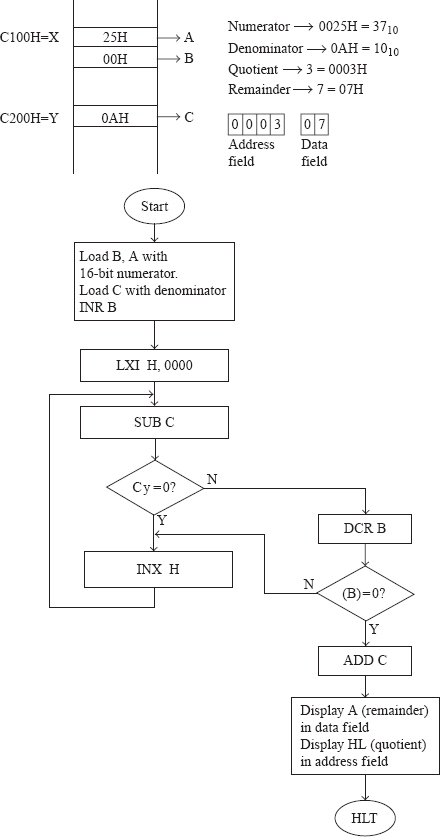
Fig. 14.10 Division of a 16-bit number by an 8-bit number
Program to divide a 16-bit number by an 8-bit number
;FILE NAME C:ALSDIV1.ASM
   ;8085 ALP TO DIVIDE A 16 BIT BINARY NUMBER STORED AT X AND X11 BY AN 8
   ;BIT BINARY NUMBER STORED AT Y. DISPLAY QUOTIENT IN THE ADDRESS FIELD
   ;AND THE REMAINDER IN THE DATA FIELD.

;USES INEFFICIENT REPEATED SUBTRACT ALGORITHM
            ORG C100H
  X:        DW 0025H

            ORG C200H
  Y:        DB 0AH

            ORG C000H
UPDAD:      EQU 06BCH
UPDDT:      EQU 06D3H
CURAD:      EQU FFF7H
CURDT:      EQU FFF9H
    LXI H, X
    MOV A, M       ;;Load A with LS byte of the numerator.
    INX H
    MOV B, M
    INR B      ;;;Load B with one more than MS byte of numerator.

    LXI H,Y
    MOV C, M ;;Load C with the denominator.

    LXI H,0;Initialize HL with 0. HL will finally have the quotient.

AGAIN:

    SUB C             ;Subtract C contents from LS byte of numerator.
    JNC INC_QUO       ;If Cy 5 0, jump to INC_QUO.
    DCR B             ;If Cy 5 1, decrement MS byte of numerator.
    JZ EXIT           ;If zero, jump to EXIT. At this point, if we add
                      ;C contents to A, we get correct remainder in A.

INC_QUO:
    INX H
    JMP AGAIN   ;;Increment quotient and jump to AGAIN.

EXIT:
    ADD C       ;Now, A contains the remainder.
    STA CURDT   ;Store remainder in CURDT.

    SHLD CURAD
    CALL UPDAD  ;;Display quotient in address field.
    CALL UPDDT  ;Display remainder in data field.
    HLT
UPDDT routine: In this program, we have used the monitor routine UPDDT, which is used to update the data field on the kit. The routine displays the contents of the byte at symbolic location CURDT.
On the ALS kit UPDDT routine is at address 06D3H, and CURDT is byte location FFF9H. Thus, if we have 78H in location FFF97H, execution of ‘CALL UPDDT’ instruction results in display of ‘78’ in the data field. CALL UPDDT is coded as CD D3 06.
In addition, if B register content is 00H, there will not be any dot at the end of the data field. If B content is 01H, a dot will be displayed at the end of the data field.
The contents of the registers A, B, C, D, E, H, L, and flags are all altered on executing CALL UPDDT.
The other common routine, RDKBD, is described in a later chapter.
- Modify the program to exchange 10 bytes such that it exchanges 4 bytes, and provide trace for the program.
- Write an 8085 assembly language program to find the largest and smallest numbers in a set of N byte-sized numbers. Display them in the address field.
- Provide trace for the previous program when N = 4.
- Write an 8085 assembly language program to find the number of 1s and 0s in a given byte. Display the number of 1s and 0s in the address field.
- Write an 8085 assembly language program to check if a given set of N bytes are unsorted, sorted in ascending order, or sorted in descending order. Store in location RES the value 00, 01, or 02 accordingly.
- Write an 8085 assembly language program to find if a triangle can be formed given the length of three sides. If triangle can be formed, store 01 in location RES, else store 00.
- Write an 8085 assembly language program to find the length of a rectangle, given the breadth and the perimeter. Strore the result in location LEN.