
7
Arithmetic Group of Instructions
![]() Instructions to perform addition
Instructions to perform addition
![]() Instruction type ADD R
Instruction type ADD R
![]() Flags register
Flags register
![]() Instruction type ADI d8
Instruction type ADI d8
![]() Instruction type INR R
Instruction type INR R
![]() Instruction type ADC R
Instruction type ADC R
![]() Instruction type ACI d8
Instruction type ACI d8
![]() Instructions to perform subtraction
Instructions to perform subtraction
![]() Instruction type SUB R
Instruction type SUB R
![]() Instruction type SUI d8
Instruction type SUI d8
![]() Instruction type DCR R
Instruction type DCR R
![]() Instruction type SBB R
Instruction type SBB R
![]() Instruction type SBI d8
Instruction type SBI d8
![]() Instruction type INX rp
Instruction type INX rp
![]() Instruction type DCX rp
Instruction type DCX rp
![]() Instruction type DAD rp
Instruction type DAD rp
![]() Decimal addition in 8085
Decimal addition in 8085
![]() BCD numbers
BCD numbers
![]() DAA instruction
DAA instruction
![]() Questions
Questions
A total of 14 instruction types covering 62 instructions will be explained in this chapter. The various instruction types to perform addition and subtraction operations are dealt with in detail in this chapter. Furthermore, the instruction types INX rp, DCX rp, and DAD rp are also discussed briefly in the latter portion of the chapter.
 7.1 INSTRUCTIONS TO PERFORM ADDITION
Intel 8085 is a primitive microprocessor. In its arithmetic group of instructions, it has only add and subtract instructions. It does not have instructions to multiply or divide numbers. In this section we discuss the instructions to perform addition.
In the addition of two numbers, 8085 imposes the restriction that one of the operands must be in the Accumulator. The other operand can be one of the following.
- —Contents of an 8-bit register,
- —Contents of memory location pointed by HL pair,
- —Eight-bit immediate data.
7.1.1 Instruction Type ADD R
ADD is a mnemonic that stands for ‘Add contents of R to accumulator’. In this case, ‘R’ stands for any of the following registers or memory location M pointed by HL pair.
R = A, B, C, D, E, H, L, or M
This instruction is used to add contents of R and accumulator. The result of the addition will be stored in the accumulator.
As R can have any of the eight values, there are eight opcodes for this type of instruction. It occupies only 1byte in memory.
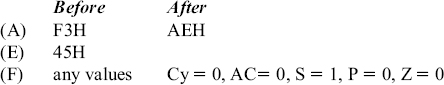
‘ADD E’ is an example instruction of this type. It is a 1-byte instruction. The result of execution of this instruction is shown below with an example.

Summary: ADD R (1 byte; ADD E; 8 opcodes)
7.1.2 FLAGS REGISTER
In the previous example, the result of addition of 45H and F3H turns out to be 38H, which is less than the original value of 45H present in the accumulator! Obviously, the user will not be happy with such state of affairs. The correct answer is 38H with carry of 1. This carry information is stored in a special 8-bit register called the flags register, F for short. A flag can be in the hoisted state, or it is not hoisted at all! Thus a flag can be represented by 1 bit of information. Thus the flags register can have a total of eight flags. But only five flags are implemented in 8085. They are:
- Carry flag (‘Cy’),
- Auxiliary carry flag (AC),
- Sign flag (S),
- Parity flag (P), and
- Zero flag (Z).
Their positions in the flags register is shown in Fig. 7.1. The positions marked ‘x’ are don't care bits in the flags register. The user is not required to memorize the positions of these flags in the flags register.

Thus the programmer's view of 8085 contains the flags register also, as shown in Fig. 7.2.

Fig. 7.2 Programmer's view of 8085 (incomplete) These individual flags are either hoisted (set to 1),
These individual flags are either hoisted (set to 1), or not hoisted (reset to 0) depending on the result of execution of an arithmetic or logical instruction. But in a few arithmetic and logical instructions, some or none of these flags are affected.
However, in any data transfer instruction, none of the flags are affected. Hence the topic of flags register was not discussed at all while explaining data transfer instructions in the previous chapter.
Carry flag (Cy): Notice that in the addition of any two 8-bit numbers, the carry generated can be either 0 or 1. Thus to store the carry information 1-bit storage is enough. The Cy flag is stored in the LS bit position in the flags register. Instructions that use the Cy flag are widely used in the user programs.
Example 1: In the addition of 45H and F3H, the result is 38H with Cy flag = 1, as shown below.

Example 2: In the addition of 85H and 1EH, the result is A3H with Cy = 0, as shown below.

Auxiliary carry flag (Ac): In the addition of any two 8-bit (2-hex digit) numbers, a carry may be generated when we add the LS hex digits of the two numbers. Such a carry is called intermediate carry, half carry, or auxiliary carry (AC). Intel prefers to call it AC. In Ex. 1, AC is not generated. In Ex. 2, AC is generated.
As this is only an intermediate carry, we are not interested in storing this information. But 8085 still stores this AC information in bit position 4 of the flags register. The result of execution of DAA instruction, to be described later, is affected by the status of this flag. However, 8085 instruction set does not provide any instruction, which explicitly uses the AC flag.
Sign flag (S): The S flag is set to 1, if the result of an arithmetic operation is negative, indicated by MS bit of 8-bit result being 1. It is reset to 0 if the result is positive, indicated by MS bit of 8-bit result being 0.
Thus, the value of S flag is essentially the value of the MS bit of the 8-bit result. In Ex. 1, as the 8-bit result is 38H = 0 011 1000, the sign flag is reset to 0. Note that we are not considering here the 9-bit result including the carry, to decide the S flag value. In Ex. 2, as the 8-bit result is A3H = 1 010 0011, the sign flag is set to 1.
If we are working with unsigned numbers, we simply ignore the S flag. For example, if we are treating 85H and 1EH as unsigned numbers, their sum will be the unsigned number A3H. In this case, S flag becomes 1, but we do not care for the value of the S flag.
Instructions that use the S flag are quite often used in the user programs.
Parity flag (P): The P flag is set to 1, if the 8-bit result of an arithmetic operation has an even number of 1's in it. If there are odd number of 1's in the 8-bit result, the P flag is reset to 0.
In Ex. 1, as the 8-bit result 38H = 0011 1000 has three numbers of 1's (an odd number), the parity flag is reset to 0. In Ex. 2, as the 8-bit result A3H = 1010 0011 has four numbers of 1's (an even number), the parity flag is set to 1.
As the user does not really care for the number of 1's present in the result after an arithmetic operation, this flag is not of much use practically.
Zero flag (Z): The Z flag is set to 1, if the 8-bit result of an arithmetic operation is 00H. If the 8-bit result is not equal to 00H, the Z flag is reset to 0. Thus the Z flag is hoisted to indicate that the result is 0.
In Ex. 1, as the 8-bit result is 38H and is non-zero, the Z flag is reset to 0. Also in Ex. 2, as the 8-bit result is A3H, the Z flag is reset to 0. Instructions that use the Z flag are widely used in the user programs.
7.1.3 INSTRUCTION TYPE ADI d8
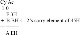
ADI is a mnemonic, which stands for ‘ADd Immediate to Accumulator’ and ‘d8’ stands for any 8-bit data. This instruction is used to add 8-bit immediate data to the Accumulator. The result of addition will be stored in the accumulator. It occupies 2-bytes in memory. The flags are affected based on the result.
‘ADI F3H’ is an example instruction of this type. It is a 2-byte instruction. The result of execution of this instruction is shown below with an example.

Summary: ADI d8 (2 bytes; ADI F3H; 1 opcode)
7.1.4 INSTRUCTION TYPE INR R
INR is a mnemonic that stands for ‘INcRement’ and ‘R’ stands for any of the following registers or memory location M pointed by HL pair.
R = A, B, C, D, E, H, L, or M
This instruction is used to add 1 to the contents of R. The result of increment will be stored in R. All flags, except Cy flag, are affected depending on the result. Many times a register content is used as a counter. If Cy flag were to be affected during increment of a counter, it causes problems in many cases, as will be seen in program examples later. So by design, Cy flag is not affected by execution of this instruction.
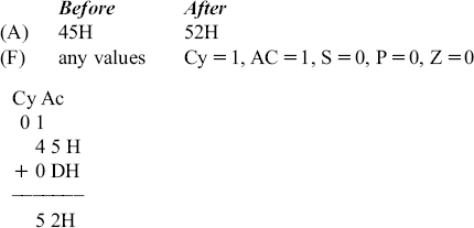
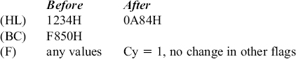
As R can have any of the eight values, there are eight opcodes for this type of instruction. It occupies only 1 byte in memory. ‘INR M’ is an example instruction of this type. It is a 1-byte instruction. The result of execution of this instruction is shown below with an example.

If contents of F850H were FFH, it becomes 00H after execution of INR M.
Summary: INR R (1 byte; INR M; 8 opcodes)
7.1.5 INSTRUCTION TYPE ADC R
There are times when a user is required to add two numbers each of which is several bytes in size. For example, let us say it is needed to add the following two 16-bit numbers.

In this example, the addition of 56H and F2H results in a sum of 48H with a carry of 1. Next, we have to add 34H and A2H along with this carry value of 1. To facilitate such an operation, 8085 provides instructions to add two numbers along with carry value.
ADC is a mnemonic that stands for ‘ADd with Carry’ and ‘R’ stands for any of the following registers, or memory location M pointed by HL pair.
R = A, B, C, D, E, H, L, or M
This instruction is used to add contents of R and Accumulator along with the carry value. The result of the addition will be stored in the Accumulator. As R can have any of the eight values, there are eight opcodes for this type of instruction. It occupies only 1 byte in memory. ‘ADC E’ is an example instruction of this type. It is a 1-byte instruction. The result of execution of this instruction is shown below with an example.

Summary: ADC R (1 byte; ADC E; 8 opcodes)
7.1.6 INSTRUCTION TYPE ACI d8
ACI is a mnemonic that stands for ‘Add with Carry Immediate to accumulator’ and ‘d8’ stands for any 8-bit data. This instruction is used to add 8-bit immediate data to the accumulator along with the carry value. The result of the addition will be stored in the accumulator. The flags are affected based on the result. It occupies 2bytes in memory.
‘ACI F3H’ is an example instruction of this type. It is a 2-byte instruction. The result of execution of this instruction is shown below with an example.

Summary: ACI d8 (2 bytes; ACI F3H; 1 opcode)
7.2 INSTRUCTIONS TO PERFORM SUBTRACTION
In this section we discuss the instructions to perform subtraction. In the subtraction of two numbers, 8085 imposes the restriction that Accumulator will have one operand from which the other operand specified by one of the following will be subtracted.
- —Contents of an 8-bit register;
- —Contents of memory location pointed by HL pair;
- —Eight-bit immediate data.
7.2.1 INSTRUCTION TYPE SUB R
SUB is a mnemonic that stands for ‘SUBtract contents of R from Accumulator’. ‘R’ stands for any of the following registers, or memory location M pointed by HL pair.
R = A, B, C, D, E, H, L, or M
This instruction is used to subtract contents of R from Accumulator. The result of the subtraction will be stored in the Accumulator. As R can have any of the eight values, there are eight opcodes for this type of instruction. It occupies only 1 byte in memory. ‘SUB E’ is an example instruction of this type. It is a 1-byte instruction. The result of execution of this instruction is shown below with examples.
Example 1:
Internally, 8085 performs this subtraction by adding the 2's complement of 45H to F3H, as shown below.
The carry generated in this addition is complemented and stored as the Cy flag value. Thus the Cy flag value after the subtraction will be 0. Note that even though it is a subtract operation, Intel prefers to use the terms carry and auxiliary carry in place of borrow and auxiliary borrow.
Example 2

Internally, 8085 performs this subtraction by adding the 2's complement of 20H to 30H, as shown in the following.

The carry generated in this addition is complemented and stored as the Cy flag value. Thus the Cy flag value after the subtraction will be 0.
Summary: SUB R (1 byte; SUB E; 8 opcodes)
7.2.2 INSTRUCTION TYPE SUI d8
SUI is a mnemonic that stands for ‘SUbtract Immediate from Accumulator’ and ‘d8’ stands for any 8-bit data. This instruction is used to subtract 8-bit immediate data from the Accumulator. The result of the subtraction will be stored in the Accumulator. The flags are affected based on the result. It occupies 2 bytes in memory. ‘SUI F3H’ is an example instruction of this type. It is a 2-byte instruction. The result of execution of this instruction is shown below with an example.
Summary: SUI d8 (2 bytes; SUI F3H; 1 opcode)
7.2.3 INSTRUCTION Type DCR R
DCR is a mnemonic, which stands for ‘DeCRement’ and ‘R’ stands for any of the following registers, or memory location M pointed by HL pair.
R = A, B, C, D, E, H, L, or M
This instruction is used to subtract 1 from the contents of R. The result of the increment will be stored in R. All flags, except Cy flag, are affected depending on the result. Many times a register content is used as a down counter. If Cy flag were to be affected during decrement of a counter, it causes problems in many cases, as will be seen in program examples later. So by design, Cy flag is not affected by the execution of this instruction.
As R can have any of the eight values, there are eight opcodes for this type of instruction. It occupies only 1 byte in memory. ‘DCR M’ is an example instruction of this type. It is a 1-byte instruction. The result of execution of this instruction is shown in the following with an example.
Internally, 8085 performs this decrement operation by adding the 2's complement of 01H to 45H. If contents of F850H were 00H, it becomes FFH after execution of DCR M.
Summary: DCR R (1 byte; DCR M; 8 opcodes)
7.2.4 INSTRUCTION TYPE SBB R
There are times when a user is required to subtract two numbers each of which is several bytes in size. For example, let us say it is needed to perform the following subtraction.

In this example, the subtraction of 56H and F2H results in 64H with a borrow of 1. Next, we have to subtract 34H and 12H along with this borrow value of 1. To facilitate such an operation, 8085 provides instructions to subtract two numbers along with the borrow value.
SBB is a mnemonic that stands for ‘SuBtract with Borrow’ and ‘R’ stands for any of the following registers, or memory location M pointed by HL pair.
R = A, B, C, D, E, H, L, or M
This instruction is used to subtract contents of R from accumulator, along with the carry value. The result of the subtraction will be stored in the Accumulator. As R can have any of the eight values, there are eight opcodes for this type of instruction. It occupies only 1 byte in memory. ‘SBB E’ is an example instruction of this type. It is a 1-byte instruction. The result of execution of this instruction is shown below with an example.

Summary: SBB R (1 byte; SBB E; 8 opcodes)
7.2.5 INSTRUCTION TYPE SBI d8
SBI is a mnemonic that stands for ‘Subtract with Borrow Immediate from Accumulator’ and ‘d8’ stands for any 8-bit data. This instruction is used to subtract 8-bit immediate data from the Accumulator along with the carry value. The result of subtraction will be stored in the Accumulator. The flags are affected based on the result. It occupies 2 bytes in memory.
‘SBI F3H’ is an example instruction of this type. It is a 2-byte instruction. The result of execution of this instruction is shown below with an example.

Summary: SBI d8 (2 bytes; SBI F3H; 1 opcode)
7.3 INSTRUCTION TYPE INX rp
INX is a mnemonic that stands for ‘INcrement eXtended register’ and ‘rp’ stands for any of the following register pairs.
rp = BC, DE, or HL
This instruction is used to add 1 to the contents of rp. The result of the increment will be stored in rp. Note that flags are not at all affected by the execution of this instruction. A register pair is generally used to store a memory address. If flags were to be affected during increment of a memory address, it causes problems in many cases, as will be seen in program examples later. So by design, flags are not affected by execution of this instruction.
As rp can have any of the three values, there are three opcodes for this type of instruction. It occupies only 1 byte in memory. ‘INX B’ is an example instruction of this type. It is a 1-byte instruction. The result of execution of this instruction is shown below with an example.
![]()
It may appear that INX B is functionally same as INR C in this example. But, if content of BC was F8FFH, it becomes F900H after execution of INX B. If content of BC was F8FFH, it becomes F800H after execution of INR C. Thus, basically, INX instruction increments a 16-bit quantity, whereas INR increments a 8-bit quantity.
Summary: INX rp (1 byte; INX B; 3 opcodes)
7.4 INSTRUCTION TYPE DCX rp
DCX is a mnemonic, which stands for ‘DeCrement eXtended register’ and ‘rp’ stands for any of the following register pairs.
rp = BC, DE, or HL
This instruction is used to subtract 1 from the contents of rp. The result of the decrement will be stored in rp. Note that flags are not at all affected by the execution of this instruction. A register pair is generally used to store a memory address. If flags were to be affected during decrement of a memory address, it causes problems in many cases, as will be seen in program examples later. So by design, flags are not affected by execution of this instruction.
As rp can have any of the three values, there are three opcodes for this type of instruction. It occupies only 1 byte in memory. ‘DCX B’ is an example instruction of this type. It is a 1-byte instruction. The result of execution of this instruction is shown below with an example.
![]()
It may appear that DCX B is functionally same as DCR C in this example. But, if content of BC was F900H, it becomes F8FFH after execution of DCX B. If content of BC was F900H, it becomes F9FFH after execution of DCR C. Thus, basically, DCX instruction decrements a 16-bit quantity, whereas DCR decrements a 8-bit quantity.
Summary: DCX rp (1 byte; DCX B; 3 opcodes)
7.5 INSTRUCTION TYPE DAD rp
Intel 8085 is basically an 8-bit microprocessor. But the designers have provided instructions to perform 16-bit additions also. As the internal architecture is only 8 bits, this instruction easily takes double the time needed to add two 8-bit numbers.
DAD is a mnemonic, which stands for ‘Double ADd’ and ‘rp’ stands for any of the following register pairs.
rp = BC, DE, or HL
This instruction is used to add contents of rp to HL. The result of the addition will be stored in HL. Thus in this instruction, HL is used as a 16-bit accumulator. Only Cy flag is affected depending on the result.
If other flags were to be affected during execution of this instruction, it causes problems in many cases, as will be seen in program examples later. So by design, flags other than Cy, are not affected by execution of this instruction.
As rp can have any of the three values, there are three opcodes for this type of instruction. It occupies only 1 byte in memory. ‘DAD B’ is an example instruction of this type. It is a 1-byte instruction. The result of execution of this instruction is shown below with an example.
Summary: DAD rp (1 byte; DAD B; 3 opcodes)
7.6 DECIMAL ADDITION IN 8085
In a digital computer everything is represented using 0s and 1s only. For example, an instruction will have a code using only 0s and 1s. Data is also represented using 0s and 1s. Data can be of different types like unsigned numbers, signed numbers, floating point numbers, binary coded decimal (BCD) numbers, etc. Thus, a series of 0s and 1s will acquire a value based on the interpretation.
7.6.1 BCD NUMBERS
Many a time, we are required to represent decimal numbers in a computer, and perform arithmetic on these numbers. For example, we may be required to total the marks a student has obtained in five different subjects, where obviously, the marks are awarded in decimal notation.
For this purpose BCD code is extensively used. In BCD notation, 4bits are used to code a digit, and so two digits of information is stored in a byte. For example, decimal 39 is represented in BCD as 0011 1001. Codes 1010, 1011, 1100, 1101, 1110, and 1111 are illegal in BCD notation. Similarly decimal 1,024 is represented in BCD as 0001 0000 0010 0100. Same decimal 1,024 is represented in binary as 0000 0100 0000 0000. As stated earlier, the value of a series of 0s and 1s depends on the interpretation.
7.6.2 DAA INSTRUCTION
Suppose we want to add the two decimal numbers 38 and 45. They will be represented in BCD as 0011 1000 and 0100 0101. The addition results in 0111 1101. If we interpret this result as a BCD number, the answer is incorrect as well as illegal. This is because, 1101 is an illegal BCD number. This is where the DAA instruction proves its usefulness. All that is required to be done is to add the BCD numbers and store the result in A, and then execute the DAA instruction.
The working of DAA instruction depends on the contents of the AL register, Cy, and AC flags. In effect, it adds 00H, 06H, 60H, or 66H to accumulator so as to get the correct BCD answer in the Accumulator.
If the LS hex digit in A is <= 9 and AC flag is 0, the LS hex digit value will not be altered.
If the LS hex digit is > 9, or if AC flag is set to 1, it adds 6 to the LS hex digit of A. It increments
the MS hex digit if this addition resulted in a carry to the MS digit position. In this process,
the Cy flag will be set to 1 if the MS hex digit was incremented from F to 0.
Now, if the MS hex digit is <= 9 and Cy flag is 0, the MS hex digit will not be altered, and Cy
flag is reset to 0.
If the MS hex digit is > 9, or if Cy flag is set to 1, it adds 6 to the MS hex digit of A and sets Cy
flag to 1.
Note that DAA instruction cannot be used for decimal subtraction. Intel 8085 does not provide an instruction for decimal subtraction. So a series of instructions are to be executed to perform decimal subtraction.
A number of examples are provided here to explain decimal addition using DAA instruction.
Example 1: Let us say, we add 45 BCD and 38 BCD, and store the result 7DH in A. In this case, Cy flag = 0 and AC flag = 0. But as D is an invalid BCD code, the DAA instruction adds 06H to A. Thus, we get 83H in A, which will now be interpreted as 83 BCD, the correct sum of 45 and 38.
Example 2: Let us say, we add 63 BCD and 88 BCD, and store the result EBH in A. In this case, Cy flag = 0 and AC flag = 0. But as both E and B are invalid BCD codes, the DAA instruction adds 66H to A. Thus, we get 51H in A, and Cy flag will be set to 1. This will now be interpreted as 51 BCD with Cy flag = 1, the correct sum of 63 and 88.
Example 3: Let us say, we add 53 BCD and 36 BCD, and store the result 89H in A. In this case, Cy flag = 0 and AC flag = 0. Since both 8 and 9 are valid BCD codes, the DAA instruction does not add anything to A. In other words, it is same as adding 00 to AL. The result in A will now be interpreted as 89 BCD, the correct sum of 53 and 36.
Example 4: Let us say, we add 99 BCD and 88 BCD, and store the result 21H in A. In this case, Cy flag = 1 and AC flag = 1. So, although both 2 and 1 are valid BCD codes, the DAA instruction adds 66H to A. Thus, we get 87H in A, and Cy flag will be set to 1. The result in A will now be interpreted as 87 BCD with Cy flag = 1, the correct sum of 99 and 88.
Example 5: Let us say, we add 63 BCD and 42 BCD, and store the result A5H in A. In this case, Cy flag = 0 and AC flag = 0. But as A is an invalid BCD code, the DAA instruction adds 60H to AL. Thus we get 05H in A, with Cy flag51, which will now be interpreted as 05 BCD with Cy flag = 1, the correct sum of 63 and 42.
- Describe the flags available in 8085.
- Assume that before the execution of any instruction we have (A) = 65H, (B) = B2H, (H) = F9H, (L) = 50H, Cy flag = 1, and content of memory location F950H is 38H. What is the value of A register and the value of different flags after the execution of each of the following?
- ADD L
- ADC B
- SUI 56H
- SBB M and
- SUB H
- Distinguish between the following pairs of instructions.
- ADD H and ADC H
- ADI 53H and ACI 53H
- ADC M and ADC H
- ADD M and DAD H
- SUB M and SUB L
- INX B and INR C
- Write a 8085 assembly language program to perform addition of BC and HL, and store in HL without using DAD instruction.
- Explain the working of DAA instruction with examples.
- Write a 8085 assembly language program to perform decimal addition without using DAA instruction.
- Write a 8085 assembly language program to perform decimal subtraction.