Day 27. Basic Switch Configuration
CCENT 100-101 ICND1 Exam Topics
![]() Configure and verify initial switch configuration, including remote access management.
Configure and verify initial switch configuration, including remote access management.
![]() Configure SVI interfaces.
Configure SVI interfaces.
![]() Verify network status and switch operation using basic utilities such as ping, telnet, and ssh.
Verify network status and switch operation using basic utilities such as ping, telnet, and ssh.
Key Topics
Today, we review the commands necessary to perform a basic initial configuration of a switch, including changing the default management VLAN and configuring SSH remote access. We will also review verification techniques such as using ping, traceroute, and show commands.
Basic Switch Configuration Commands
Table 27-1 reviews basic switch configuration commands.
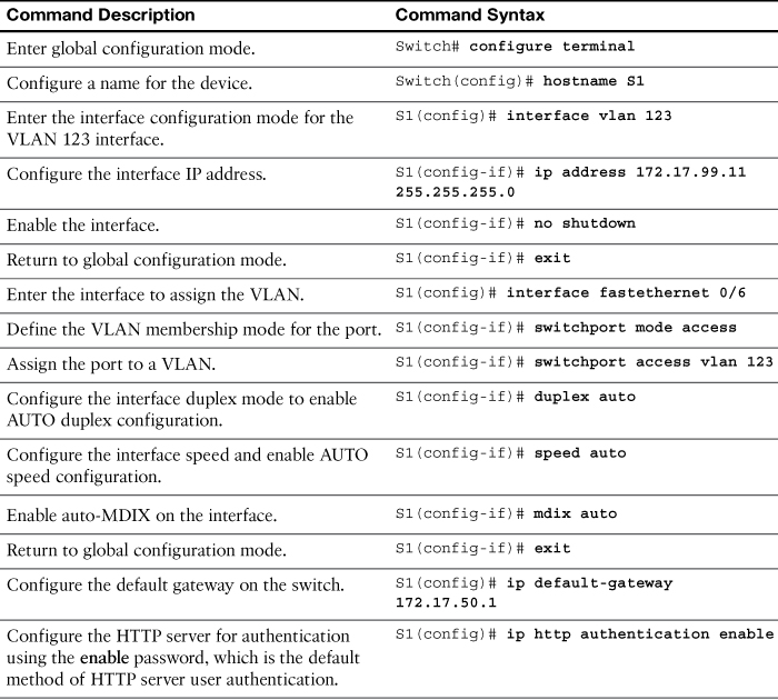


In reference to the commands in Table 27-1, keep in mind the following:
![]() The default VLAN for all ports is VLAN 1. Because it is a best practice to use a VLAN other than the default VLAN 1 as the management VLAN, the command in the table uses VLAN 123.
The default VLAN for all ports is VLAN 1. Because it is a best practice to use a VLAN other than the default VLAN 1 as the management VLAN, the command in the table uses VLAN 123.
![]() By default, the native VLAN assigned to 802.1Q trunks is also VLAN 1. It is a security best practice to define a dummy VLAN as the native VLAN—a VLAN that is distinct from all other VLANs. We discuss trunking configuration on Day 25, “VLAN and Trunking Configuration.”
By default, the native VLAN assigned to 802.1Q trunks is also VLAN 1. It is a security best practice to define a dummy VLAN as the native VLAN—a VLAN that is distinct from all other VLANs. We discuss trunking configuration on Day 25, “VLAN and Trunking Configuration.”
![]() Although the enable password command is shown in the table for completeness, this command is superseded by the enable secret command. If both are entered, IOS ignores the enable password command.
Although the enable password command is shown in the table for completeness, this command is superseded by the enable secret command. If both are entered, IOS ignores the enable password command.
![]() Although the configuration for Telnet is shown, configuring SSH is a best practice. SSH configuration is reviewed in the next section.
Although the configuration for Telnet is shown, configuring SSH is a best practice. SSH configuration is reviewed in the next section.
![]() To configure multiple ports with the same command, use the interface range command. For example, to configure ports 6–10 as access ports belonging to VLAN 10, you would enter the following:
To configure multiple ports with the same command, use the interface range command. For example, to configure ports 6–10 as access ports belonging to VLAN 10, you would enter the following:
Switch(config)# interface range FastEthernet 0/6 – 10
Switch(config-if-range)# switchport mode access
Switch(config-if-range)# switchport access vlan 10
Half-Duplex, Full-Duplex, and Port Speed
Half-duplex communication is unidirectional data flow in which a device can either send or receive on an Ethernet LAN, but not both at the same time. Today’s LAN networking devices and end device network interface cards (NIC) operate at full duplex as long as the device is connected to another full-duplex–capable device. Full-duplex communication increases effective bandwidth by allowing both ends of a connection to transmit and receive data simultaneously; this is known as bidirectional. This microsegmented LAN is collision free. Gigabit Ethernet and 10Gbps NICs require full-duplex connections to operate. Port speed is simply the bandwidth rating of the port. The most common speeds today are 100Mbps, 1Gbps, and 10Gbps.
Although the default duplex and speed setting for Cisco Catalyst 2960 and 3560 switches is auto, the speed and duplex commands can be manually configured.
Note
Setting the duplex mode and speed of switch ports can cause issues if one of the ends is mismatched or set to autonegotiation. Also, all fiber-optic ports, such as 100BASE-FX ports, operate only at one preset speed and are always full duplex.
Automatic Medium-Dependent Interface Crossover (auto-MDIX)
Until recently, switch-to-switch or switch-to-router connections required using different Ethernet cables (crossover or straight-through). Using the automatic medium-dependent interface crossover (auto-MDIX) feature on an interface eliminates this problem. When auto-MDIX is enabled, the interface automatically detects the required cable connection type (straight-through or crossover) and configures the connection appropriately. The auto-MDIX feature is enabled by default on Catalyst 2960 and Catalyst 3560 switches but is not available on the older Catalyst 2950 and Catalyst 3550 switches. The Gigabit Ethernet standard requires auto-MDIX, so any 1000Mbps port will have this capability. When using auto-MDIX on an interface, the interface speed and duplex must be set to auto so that the feature operates correctly.
Configuring SSH Access
Secure Shell (SSH) is recommended as the protocol to use for remote device management. Configuring SSH (port 22) is a security best practice because Telnet (port 23) uses insecure plain-text transmission of both the login and the data across the connection. Example 27-1 displays an SSH configuration.
Example 27-1 Configuring SSH Remote Access on a Switch
S1# show ip ssh
SSH Disabled - version 1.99
%Please create RSA keys to enable SSH (of at least 768 bits size) to enable SSH v2.
Authentication timeout: 120 secs; Authentication retries: 3
S1# conf t
S1(config)# ip domain-name cisco.com
S1(config)# crypto key generate rsa
The name for the keys will be: S1.cisco.com
Choose the size of the key modulus in the range of 360 to 4096 for your
General Purpose Keys. Choosing a key modulus greater than 512 may take
a few minutes.
How many bits in the modulus [512]:1024
% Generating 1024 bit RSA keys, keys will be non-exportable...
[OK] (elapsed time was 4 seconds)
*Mar 1 02:20:18.529: %SSH-5-ENABLED: SSH 1.99 has been enabled
S1(config)# line vty 0 15
S1(config-line)# login local
S1(config-line)# transport input ssh
S1(config-line)# user admin password ccna
!The following commands are optional SSH configurations.
S1(config)# ip ssh version 2
S1(config)# ip ssh authentication-retries 5
S1(config)# ip ssh time-out 60
S1(config)# end
S1# show ip ssh
SSH Enabled - version 2.0
Authentication timeout: 60 secs; Authentication retries: 5
S1#
The following description details the steps shown in Example 27-1:
Step 1. Verify that the switch supports SSH using the show ip ssh command. If the command is not recognized, you know that SSH is not supported.
Step 2. Configure a DNS domain name with the ip domain-name domain-name global configuration command.
Step 3. Configure the switch using the crypto key generate rsa command to generate an RSA key pair and automatically enable SSH. When generating RSA keys, you are prompted to enter a modulus length. Cisco recommends a minimum modulus size of 1024 bits, as shown in Example 27-1.
Note
To remove the RSA key pair, use the crypto key zeroize rsa command. This will disable the SSH service.
Step 4. Change the vty lines to use usernames, with either locally configured usernames or an authentication, authorization, and accounting (AAA) server. In Example 27-1, the login local vty subcommand defines the use of local usernames, replacing the login vty subcommand.
Step 5. Configure the switch to accept only SSH connections with the transport input ssh vty subcommand. (The default is transport input telnet.)
Step 6. Add one or more username username password password global configuration commands to configure username/password pairs.
Step 7. If desired, you can modify the default SSH configuration to change the SSH version to 2.0, the number of authentication tries, and the timeout, as shown in Example 27-1.
Step 8. Verify your SSH parameters using the show ip ssh command.
Verifying Network Connectivity
Using and interpreting the output of various testing tools are often the first steps in isolating the cause of a network connectivity issue. The ping command can be used to systematically test connectivity in the following manner:
![]() Can an end device ping itself?
Can an end device ping itself?
![]() Can an end device ping its default gateway?
Can an end device ping its default gateway?
![]() Can an end device ping the destination?
Can an end device ping the destination?
By using the ping command in this ordered sequence, you can isolate problems faster. If local connectivity is not an issue—in other words, the end device can successfully ping its default gateway—using the traceroute utility can help isolate at what point in the path from source to destination that the traffic stops.
As a first step in the testing sequence, verify the operation of the TCP/IP stack on the local host by pinging the loopback address, 127.0.0.1, as demonstrated in Example 27-2.
Example 27-2 Testing the TCP/IP Stack on a Windows PC
C:> ping 127.0.0.1
Pinging 127.0.0.1 with 32 bytes of data:
Reply from 127.0.0.1: bytes=32 time<1ms TTL=64
Reply from 127.0.0.1: bytes=32 time<1ms TTL=64
Reply from 127.0.0.1: bytes=32 time<1ms TTL=64
Reply from 127.0.0.1: bytes=32 time<1ms TTL=64
Ping statistics for 127.0.0.1:
Packets: Sent = 4, Received = 4, Lost = 0 (0% loss),
Approximate round trip times in milli-seconds:
Minimum = 0ms, Maximum = 0ms, Average = 0ms
Because this test should succeed regardless of whether the host is connected to the network, a failure indicates a software or hardware problem on the host itself. Either the network interface is not operating properly or possibly support for the TCP/IP stack has been inadvertently removed from the operating system.
Next, verify connectivity to the default gateway. Determine the default gateway address using ipconfig and then attempt to ping it, as demonstrated in Example 27-3.
Example 27-3 Testing Connectivity to the Default Gateway on a Windows PC
C:> ipconfig
Windows IP Configuration
Ethernet adapter Local Area Connection:
Connection-specific DNS Suffix . : cisco.com
IP Address. . . . . . . . . . . . : 192.168.1.25
Subnet Mask . . . . . . . . . . . : 255.255.255.0
Default Gateway . . . . . . . . . : 192.168.1.1
C:> ping 192.168.1.1
Pinging 192.168.1.1 with 32 bytes of data:
Reply from 192.168.1.1: bytes=32 time=162ms TTL=255
Reply from 192.168.1.1: bytes=32 time=69ms TTL=255
Reply from 192.168.1.1: bytes=32 time=82ms TTL=255
Reply from 192.168.1.1: bytes=32 time=72ms TTL=255
Ping statistics for 192.168.1.1:
Packets: Sent = 4, Received = 4, Lost = 0 (0% loss),
Approximate round trip times in milli-seconds:
Minimum = 69ms, Maximum = 162ms, Average = 96ms
Failure here can indicate several problems, each of which will need to be checked in a systematic sequence. One possible order might be the following:
1. Is the cabling from the PC to the switch correct? Are link lights lit?
2. Is the configuration on the PC correct according to the logical map of the network?
3. Are the affected interfaces on the switch the cause of the problem? Is there a duplex, speed, or auto-MDIX mismatch? Are there VLAN misconfigurations?
4. Is the cabling from the switch to the router correct? Are link lights lit?
5. Is the configuration on the router interface correct according to the logical map of the network? Is the interface active?
Finally, verify connectivity to the destination by pinging it. Assume that we are trying to reach a server at 192.168.3.100. Example 27-4 shows a successful ping test to the destination.
Example 27-4 Testing Connectivity to the Destination on a Windows PC
PC> ping 192.168.3.100
Pinging 192.168.3.100 with 32 bytes of data:
Reply from 192.168.3.100: bytes=32 time=200ms TTL=126
Reply from 192.168.3.100: bytes=32 time=185ms TTL=126
Reply from 192.168.3.100: bytes=32 time=186ms TTL=126
Reply from 192.168.3.100: bytes=32 time=200ms TTL=126
Ping statistics for 192.168.3.100:
Packets: Sent = 4, Received = 4, Lost = 0 (0% loss),
Approximate round trip times in milli-seconds:
Minimum = 185ms, Maximum = 200ms, Average = 192ms
Failure here would indicate a failure in the path beyond the default gateway interface because we already successfully tested connectivity to the default gateway. From a Windows PC, the best tool to use to find the break in the path is the tracert command, as demonstrated in Example 27-5.
Note
Both Mac OS X and Linux use the traceroute command.
Example 27-5 Tracing the Route from a Windows PC
C:> tracert 192.168.3.100
Tracing route to 192.168.3.100 over a maximum of 30 hops:
1 97 ms 75 ms 72 ms 192.168.1.1
2 104 ms 119 ms 117 ms 192.168.2.2
3 * * * Request timed out.
4 * * * Request timed out.
5 * * * Request timed out.
6 ^C
C:>
Note
The reason for failure at hops 3, 4, and 5 in Example 27-5 could be that these routers are configured to not send ICMP messages back to the source.
The last successful hop on the way to the destination was 192.168.2.2. If you have administrator rights to 192.168.2.2, you could continue your research by remotely accessing the command line on 192.168.2.2 and investigating why traffic will not go any further. Also, other devices between 192.168.2.2 and 192.168.3.100 could be the source of the problem. The point is, you want to use your ping and tracert tests as well as your network documentation to proceed in a logical sequence from source to destination.
Regardless of how simple or complex your network is, using ping and tracert from the source to the destination is a simple yet powerful way to systematically verify end-to-end connectivity as well as to locate breaks in a path from one source to one destination.
Study Resources
For today’s exam topics, refer to the following resources for more study.
