
Day 9. NAT
CCENT 100-101 ICND1 Exam Topics
![]() Identify the basic operation of NAT.
Identify the basic operation of NAT.
![]() Configure and verify NAT for given network requirements.
Configure and verify NAT for given network requirements.
Key Topics
To cope with the depletion of IPv4 addresses, several short-term solutions were developed. One short-term solution is to use private addresses and Network Address Translation (NAT). NAT enables inside network hosts to borrow a legitimate Internet IPv4 address while accessing Internet resources. When the requested traffic returns, the legitimate IPv4 address is repurposed and available for the next Internet request by an inside host. Using NAT, network administrators need only one or a few IPv4 addresses for the router to provide to the hosts, instead of one unique IPv4 address for every client joining the network. Although IPv6 ultimately solves the problem NAT was created to address—IPv4 address space depletion—it is still in wide use in current network implementation strategies. Today, we review the concepts, configuration, and troubleshooting of NAT.
Network Time Protocol (NTP) is used enterprise-wide to synchronize the clocks of all networking devices. This is important so that syslog messages are stamped with the correct time, thus facilitating accurate problem isolation and troubleshooting as well as guarding against malicious attacks aimed at manipulating the clocks and syslog messages. Today, we review NTP concepts, configuration, and verification tasks.
NAT Concepts
NAT, defined in RFC 3022, has many uses. But its key use is to conserve IPv4 addresses by allowing networks to use private IPv4 addresses. NAT translates nonroutable, private, internal addresses into routable, public addresses. NAT also has the benefit of hiding internal IPv4 addresses from outside networks.
A NAT-enabled device typically operates at the border of a stub network. Figure 9-1 shows the master topology used during today’s review. R2 is the border router and will be the device used for today’s example configurations.
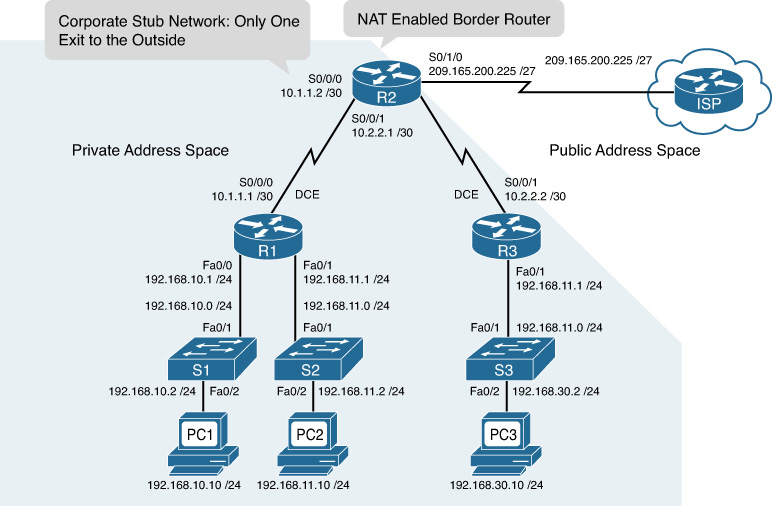
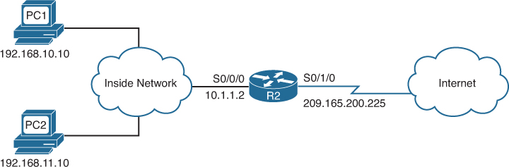
In NAT terminology, the inside network is the set of networks that are subject to translation (every network in the shaded region in Figure 9-1). The outside network refers to all other addresses. Figure 9-2 shows how to refer to the addresses when configuring NAT:
![]() Inside local address: Most likely a private address. In the figure, the IPv4 address 192.168.10.10 assigned to PC1 is an inside local address.
Inside local address: Most likely a private address. In the figure, the IPv4 address 192.168.10.10 assigned to PC1 is an inside local address.
![]() Inside global address: A valid public address that the inside host is given when it exits the NAT router. When traffic from PC1 is destined for the web server at 209.165.201.1, R2 must translate the inside local address to an inside global address, which is 209.165.200.226 in this case.
Inside global address: A valid public address that the inside host is given when it exits the NAT router. When traffic from PC1 is destined for the web server at 209.165.201.1, R2 must translate the inside local address to an inside global address, which is 209.165.200.226 in this case.
![]() Outside global address: A reachable IPv4 address assigned to a host on the Internet. For example, the web server can be reached at IPv4 address 209.165.201.1.
Outside global address: A reachable IPv4 address assigned to a host on the Internet. For example, the web server can be reached at IPv4 address 209.165.201.1.
![]() Outside local address: The local IPv4 address assigned to a host on the outside network. In most situations, this address is identical to the outside global address of that outside device. (Outside local addresses are beyond CCENT and CCNA scope.)
Outside local address: The local IPv4 address assigned to a host on the outside network. In most situations, this address is identical to the outside global address of that outside device. (Outside local addresses are beyond CCENT and CCNA scope.)

A NAT Example
Referring to Figure 9-1, the following steps illustrate the NAT process when PC1 sends traffic to the Internet:
1. PC1 sends a packet destined for the Internet to R1, the default gateway.
2. R1 forwards the packet to R2, as directed by its routing table.
3. R2 refers to its routing table and identifies the next hop as the ISP router. It then checks to see whether the packet matches the criteria specified for translation. R2 has an ACL that identifies the inside network as a valid host for translation. Therefore, it translates an inside local IPv4 address to an inside global IPv4 address, which in this case is 209.165.200.226. It stores this mapping of the local to global address in the NAT table.
4. R2 modifies the packet with the new source IPv4 address (the inside global address) and sends it to the ISP router.
5. The packet eventually reaches its destination, which then sends its reply to the inside global address 209.165.200.226.
6. When replies from the destination arrive back at R2, it consults the NAT table to match the inside global address to the correct inside local address. R2 then modifies the packet, inserting the inside local address (192.168.10.10) as the destination address and sending it to R1.
7. R1 receives the packet and forwards it to PC1.
![]() Dynamic NAT: Uses a pool of public addresses and assigns them on a first-come, first-served basis or reuses an existing public address configured on an interface. When a host with a private IPv4 address requests access to the Internet, dynamic NAT chooses an IPv4 address from the pool that is not already in use by another host. Instead of using a pool, dynamic NAT can be configured to overload an existing public address configured on an interface.
Dynamic NAT: Uses a pool of public addresses and assigns them on a first-come, first-served basis or reuses an existing public address configured on an interface. When a host with a private IPv4 address requests access to the Internet, dynamic NAT chooses an IPv4 address from the pool that is not already in use by another host. Instead of using a pool, dynamic NAT can be configured to overload an existing public address configured on an interface.
![]() Static NAT: Uses a one-to-one mapping of local and global addresses, and these mappings remain constant. Static NAT is particularly useful for web servers or hosts that must have a consistent address that is accessible from the Internet.
Static NAT: Uses a one-to-one mapping of local and global addresses, and these mappings remain constant. Static NAT is particularly useful for web servers or hosts that must have a consistent address that is accessible from the Internet.
NAT Overload
NAT overloading (also called Port Address Translation [PAT]) maps multiple private IPv4 addresses to a single public IPv4 address or a few addresses. To do this, each private address is also tracked by a port number. When a response comes back from the outside, source port numbers determine to which client the NAT router translates the packets.
Figure 9-3 and the following steps illustrate the NAT overload process.

1. PC1 and PC2 send packets destined for the Internet.
2. When the packets arrive at R2, NAT overload changes the source address to the inside global IPv4 address and keeps a record of the assigned source port numbers (1555 and 1331, in this example) to identify the client from which the packets originated.
3. R2 updates its NAT table. Notice the assigned ports. R2 then routes the packets to the Internet.
4. When the web server replies, R2 uses the destination source port to translate the packet to the correct client.
NAT overload attempts to preserve the original source port. However, if this source port is already used, NAT overload assigns the first available port number starting from the beginning of the appropriate port group 0–511, 512–1023, or 1024–65535.
NAT Benefits
The benefits of using NAT include the following:
![]() NAT conserves registered IPv4 address space because, with NAT overload, internal hosts can share a single public IPv4 address for all external communications.
NAT conserves registered IPv4 address space because, with NAT overload, internal hosts can share a single public IPv4 address for all external communications.
![]() NAT increases the flexibility of connections to the public network. Multiple pools, backup pools, and load-balancing pools can be implemented to ensure reliable public network connections.
NAT increases the flexibility of connections to the public network. Multiple pools, backup pools, and load-balancing pools can be implemented to ensure reliable public network connections.
![]() NAT allows the existing scheme to remain while supporting a new public addressing scheme. This means that an organization could change ISPs and not need to change any of its inside clients.
NAT allows the existing scheme to remain while supporting a new public addressing scheme. This means that an organization could change ISPs and not need to change any of its inside clients.
![]() NAT provides a layer of network security because private networks do not advertise their inside local addresses outside the organization. However, the phrase “NAT firewall” is misleading. NAT does not replace firewalls.
NAT provides a layer of network security because private networks do not advertise their inside local addresses outside the organization. However, the phrase “NAT firewall” is misleading. NAT does not replace firewalls.
NAT Limitations
The limitations of using NAT include the following:
![]() Performance is degraded: NAT increases switching delays because translating each IPv4 address within the packet headers takes time.
Performance is degraded: NAT increases switching delays because translating each IPv4 address within the packet headers takes time.
![]() End-to-end functionality is degraded: Many Internet protocols and applications depend on end-to-end functionality, with unmodified packets forwarded from the source to the destination.
End-to-end functionality is degraded: Many Internet protocols and applications depend on end-to-end functionality, with unmodified packets forwarded from the source to the destination.
![]() End-to-end IP traceability is lost: It becomes much more difficult to trace packets that undergo numerous packet address changes over multiple NAT hops, making troubleshooting challenging.
End-to-end IP traceability is lost: It becomes much more difficult to trace packets that undergo numerous packet address changes over multiple NAT hops, making troubleshooting challenging.
![]() Tunneling is more complicated: Using NAT also complicates tunneling protocols, such as IPsec, because NAT modifies values in the headers that interfere with the integrity checks done by IPsec and other tunneling protocols.
Tunneling is more complicated: Using NAT also complicates tunneling protocols, such as IPsec, because NAT modifies values in the headers that interfere with the integrity checks done by IPsec and other tunneling protocols.
![]() Services can be disrupted: Services that require the initiation of TCP connections from the outside network, or stateless protocols such as those using UDP, can be disrupted.
Services can be disrupted: Services that require the initiation of TCP connections from the outside network, or stateless protocols such as those using UDP, can be disrupted.
Configuring Static NAT
Static NAT is a one-to-one mapping between an inside address and an outside address. Static NAT allows connections initiated by external devices to access inside devices. For example, you might want to map an inside global address to a specific inside local address that is assigned to your inside web server. The steps and syntax to configure static NAT are as follows:
Step 1. Configure the static translation of an inside local address to an inside global address:
Router(config)# ip nat inside source static local-ip global-ip
Step 2. Specify the inside interface:
Router(config)# interface type number
Router(config-if)# ip nat inside
Step 3. Specify the outside interface:
Router(config)# interface type number
Router(config-if)# ip nat outside
Figure 9-4 shows a sample static NAT topology.

Example 9-1 shows the static NAT configuration.
Example 9-1 Static NAT Configuration
R2(config)# ip nat inside source static 192.168.10.254 209.165.200.254
R2(config)# interface serial0/0/0
R2(config-if)# ip nat inside
R2(config-if)# interface serial 0/1/0
R2(config-if)# ip nat outside
This configuration statically maps the inside private IPv4 address of 192.168.10.254 to the outside public IPv4 address of 209.165.200.254. This allows outside hosts to access the internal web server using the public IPv4 address 209.165.200.254.
Configuring Dynamic NAT
Dynamic NAT maps private IPv4 addresses to public addresses drawn from a NAT pool. The steps and syntax to configure dynamic NAT are as follows:
Step 1. Define a pool of global addresses to be allocated:
Router(config)# ip nat pool name start-ip end-ip {netmask netmask |
prefix-length prefix-length}
Step 2. Define a standard access list permitting those addresses that are to be translated:
Router(config)# access-list access-list-number source source-wildcard
Step 3. Bind the pool of addresses to the access list:
Router(config)# ip nat inside source list access-list-number pool name
Step 4. Specify the inside interface:
Router(config)# interface type number
Router(config-if)# ip nat inside
Step 5. Specify the outside interface:
Router(config)# interface type number
Router(config-if)# ip nat outside
Figure 9-5 shows a sample dynamic NAT topology.
Example 9-2 shows the dynamic NAT configuration.
Example 9-2 Dynamic NAT Configuration
R2(config)# ip nat pool NAT-POOL1 209.165.200.226 209.165.200.240 netmask
255.255.255.224
R2(config)# access-list 1 permit 192.168.0.0 0.0.255.255
R2(config)# ip nat inside source list 1 pool NAT-POOL1
R2(config)# interface serial 0/0/0
R2(config-if)# ip nat inside
R2(config-if)# interface serial s0/1/0
R2(config-if)# ip nat outside
Configuring NAT Overload
Commonly with home networks and small- to medium-sized businesses, the ISP assigns only one registered IPv4 address to your router. Therefore, it is necessary to overload that one IPv4 address so that multiple inside clients can use it simultaneously.
The configuration is similar to dynamic NAT, except that instead of a pool of addresses, the interface keyword is used to identify the outside IPv4 address. The overload keyword enables PAT so that source port numbers are tracked during translation.
Example 9-3 shows how R2 in Figure 9-5 would be configured to overload its registered IPv4 address on the serial interface.
Example 9-3 Configuring NAT to Overload an Interface Address
R2(config)# access-list 1 permit 192.168.0.0 0.0.255.255
R2(config)# ip nat inside source list 1 interface serial 0/1/0 overload
R2(config)# interface serial 0/0/0
R2(config-if)# ip nat inside
R2(config-if)# interface serial s0/1/0
R2(config-if)# ip nat outside
You can also overload a NAT pool of addresses, which might be necessary in organizations that potentially have many clients simultaneously needing translations. In our previous Example 9-2, NAT is configured with a pool of 15 addresses (209.165.200.226–209.165.200.240). If, at any given moment, R2 is translating all 15 addresses, packets for the 16th client will be queued for processing and possibly time out. To avoid this problem, add the keyword overload to the command that binds the access list to the NAT pool as follows:
R2(config)# ip nat inside source list 1 pool NAT-POOL1 overload
Interestingly, IOS will use the first IPv4 address in the pool until it runs out of available port numbers. Then it will move to the next IPv4 address in the pool.
Verifying NAT
Assume that both the static and dynamic NAT topologies shown in Figures 9-4 and 9-5 are configured on R2 with the inside server statically translated to 209.165.200.254 and the NAT-POOL1 configured with the overload keyword. Further, assume that two inside clients have connected to an outside host. You can use the show ip nat translations command to verify the current translations in the R2 NAT table, as shown in Example 9-4.
Example 9-4 Verifying NAT Operations with show ip nat translations
R2# show ip nat translations
Pro Inside global Inside local Outside local Outside global
--- 209.165.200.254 192.168.10.254 --- ---
tcp 209.165.200.226:47392 192.168.10.10:47392 209.165.201.30:80 209.165.201.30:80
tcp 209.165.200.226:50243 192.168.11.10:50243 209.165.201.30:80 209.165.201.30:80
The static entry is always in the table. Currently, there are two dynamic entries. Notice that both inside clients received the same inside global address, but the source port numbers are different (47392 for PC1 and 50243 for PC2).
The show ip nat statistics command, shown in Example 9-5, displays information about the total number of active translations, NAT configuration parameters, how many addresses are in the pool, and how many have been allocated.
Example 9-5 Verifying NAT Operations with show ip nat statistics
R2# show ip nat statistics
Total translations: 3 (1 static, 2 dynamic, 2 extended)
Outside Interfaces: Serial0/1/0
Inside Interfaces: FastEthernet0/0 , Serial0/0/0 , Serial0/0/1
Hits: 29 Misses: 7
Expired translations: 5
Dynamic mappings:
-- Inside Source
access-list 1 pool NAT-POOL1 refCount 2
pool NAT-POOL1: netmask 255.255.255.224
start 209.165.200.226 end 209.165.200.240
type generic, total addresses 3 , allocated 1 (7%), misses 0
Alternatively, use the show run command and look for NAT, access command list, interface, or pool-related commands with the required values. Examine the output from these commands carefully to discover any errors.
It is sometimes useful to clear the dynamic entries sooner than the default. This is especially true when testing the NAT configuration. To clear dynamic entries before the timeout has expired, use the clear ip nat translation * privileged EXEC command.
Troubleshooting NAT
When you have IP connectivity problems in a NAT environment, it is often difficult to determine the cause of the problem. The first step in solving your problem is to rule out NAT as the cause. Follow these steps to verify that NAT is operating as expected:
Step 1. Based on the configuration, clearly define what NAT is supposed to achieve. This might reveal a problem with the configuration.
Step 2. Verify that correct translations exist in the translation table using the show ip nat translations command.
Step 3. Use the clear and debug commands to verify that NAT is operating as expected. Check to see whether dynamic entries are re-created after they are cleared.
Step 4. Review in detail what is happening to the packet, and verify that routers have the correct routing information to forward the packet.
Use the debug ip nat command to verify the operation of the NAT feature by displaying information about every packet that the router translates, as shown in Example 9-6.
Example 9-6 Troubleshooting NAT with debug ip nat
R2# debug ip nat
IP NAT debugging is on
R2#
NAT: s=192.168.10.10->209.165.200.226, d=209.165.201.30[8]
NAT*: s=209.165.201.30, d=209.165.200.226->192.168.10.10[8]
NAT: s=192.168.10.10->209.165.200.226, d=209.165.201.30[8]
NAT: s=192.168.10.10->209.165.200.226, d=209.165.201.30[8]
NAT*: s=209.165.201.30, d=209.165.200.226->192.168.10.10[8]
NAT*: s=209.165.201.30, d=209.165.200.226->192.168.10.10[8]
NAT: s=192.168.10.10->209.165.200.226, d=209.165.201.30[8]
NAT: s=192.168.10.10->209.165.200.226, d=209.165.201.30[8]
NAT*: s=209.165.201.30, d=209.165.200.226->192.168.10.10[8]
NAT*: s=209.165.201.30, d=209.165.200.226->192.168.10.10[8]
NAT: s=192.168.10.10->209.165.200.226, d=209.165.201.30[8]
R2#
You can see that inside host 192.168.10.10 initiated traffic to outside host 209.165.201.30 and has been translated into address 209.165.200.226.
When decoding the debug output, note what the following symbols and values indicate:
![]() *: The asterisk next to NAT indicates that the translation is occurring in the fast-switched path. The first packet in a conversation is always process-switched, which is slower. The remaining packets go through the fast-switched path if a cache entry exists.
*: The asterisk next to NAT indicates that the translation is occurring in the fast-switched path. The first packet in a conversation is always process-switched, which is slower. The remaining packets go through the fast-switched path if a cache entry exists.
![]() s=: Refers to the source IPv4 address.
s=: Refers to the source IPv4 address.
![]() a.b.c.d->w.x.y.z: Indicates that source address a.b.c.d is translated into w.x.y.z.
a.b.c.d->w.x.y.z: Indicates that source address a.b.c.d is translated into w.x.y.z.
![]() d=: Refers to the destination IPv4 address.
d=: Refers to the destination IPv4 address.
![]() [xxxx]: The value in brackets is the IP identification number. This information can be useful for debugging because it enables correlation with other packet traces from protocol analyzers.
[xxxx]: The value in brackets is the IP identification number. This information can be useful for debugging because it enables correlation with other packet traces from protocol analyzers.
NAT for IPv6
We finish our NAT review with a quick look at NAT for IPv6. IPv6 was developed with the intention of making NAT for IPv4 unnecessary. However, IPv6 does include its own IPv6 private address space and NAT, which are implemented differently than they are for IPv4.
IPv6 Private Address Space
IPv6 unique local addresses (ULA) are similar to RFC 1918 private addresses in IPv4, but there are significant differences as well. The intent of unique local addresses is to provide IPv6 address space for communications within a local site. It is not meant to provide additional IPv6 address space, nor is it meant to provide a level of security.
As shown in Figure 9-6, unique local addresses have the prefix FC00::/7, which results in a first hextet range of FC00–FDFF.

ULAs are also known as local IPv6 addresses (not to be confused with IPv6 link-local addresses). Unlike private IPv4 addresses, it has not been the intention of the Internet Engineering Task Force (IETF) to use a form of NAT to translate between unique local addresses and IPv6 global unicast addresses. The implementation and potential uses for IPv6 unique local addresses are still being examined by the Internet community.
Purpose of NAT for IPv6
NAT for IPv6 is used in a much different context than NAT for IPv4. The varieties of NAT for IPv6 are used to transparently provide access between IPv6-only and IPv4-only networks, as shown in Figure 9-7. It is not used as a form of private IPv6–to–global IPv6 translation.

Over the years, there have been several types of NAT for IPv6 including NAT-PT (Network Address Translation – Protocol Translation). NAT-PT has been deprecated by the IETF in favor of its replacement, NAT64 (the 64 stands for IPv6 to IPv4 translation). NAT64 is beyond the CCENT and CCNA scope. However, be prepared to answer questions about the major differences between NAT for IPv4 and NAT for IPv6.
Note
If you would like a detailed explanation of NAT64, see Chapter 11 in Rick Graziani’s Cisco Press book, IPv6 Fundamentals.
Study Resources
For today’s exam topics, refer to the following resources for more study.
