Day 20. Basic Routing Concepts
CCENT 100-101 ICND1 Exam Topics
![]() Describe basic routing concepts.
Describe basic routing concepts.
![]() Differentiate methods of routing and routing protocols.
Differentiate methods of routing and routing protocols.
Key Topics
Today we review basic routing concepts, including exactly how a packet is processed by intermediary devices (routers) on its way from source to destination. We then review the basic routing methods, including connected, static, and dynamic routes. Tomorrow’s review will dive deeper into dynamic routing.
Packet Forwarding
Packet forwarding by routers is accomplished through path determination and switching functions. The path determination function is the process of how the router determines which path to use when forwarding a packet. To determine the best path, the router searches its routing table for a network address that matches the packet’s destination IP address.
One of three path determinations results from this search:
![]() Directly connected network: If the destination IP address of the packet belongs to a device on a network that is directly connected to one of the router’s interfaces, that packet is forwarded directly to that device. This means that the destination IP address of the packet is a host address on the same network as this router’s interface.
Directly connected network: If the destination IP address of the packet belongs to a device on a network that is directly connected to one of the router’s interfaces, that packet is forwarded directly to that device. This means that the destination IP address of the packet is a host address on the same network as this router’s interface.
![]() Remote network: If the destination IP address of the packet belongs to a remote network, the packet is forwarded to another router. Remote networks can be reached only by forwarding packets to another router.
Remote network: If the destination IP address of the packet belongs to a remote network, the packet is forwarded to another router. Remote networks can be reached only by forwarding packets to another router.
![]() No route determined: If the destination IP address of the packet does not belong to either a connected or remote network and the router does not have a default route, the packet is discarded. The router sends an Internet Control Message Protocol (ICMP) Unreachable message to the source IP address of the packet.
No route determined: If the destination IP address of the packet does not belong to either a connected or remote network and the router does not have a default route, the packet is discarded. The router sends an Internet Control Message Protocol (ICMP) Unreachable message to the source IP address of the packet.
In the first two results, the router completes the process by switching the packet out the correct interface. It does this by reencapsulating the IP packet into the appropriate Layer 2 data-link frame format for the exit interface. The type of Layer 2 encapsulation is determined by the type of interface. For example, if the exit interface is Fast Ethernet, the packet is encapsulated in an Ethernet frame. If the exit interface is a serial interface configured for PPP, the IP packet is encapsulated in a PPP frame.
Path Determination and Switching Function Example
Most of the study resources have detailed examples with excellent graphics that explain the path determination and switching functions performed by routers as a packet travels from source to destination.
Although we do not have an abundance of room here to repeat those graphics, we can textually review an example using one graphic, shown in Figure 20-1.

For brevity, only the last two octets of the MAC address are shown in the figure:
1. PC1 has a packet to be sent to PC2.
Using the AND operation on the destination’s IP address and PC1’s subnet mask, PC1 has determined that the IP source and IP destination addresses are on different networks. Therefore, PC1 checks its Address Resolution Protocol (ARP) table for the IP address of the default gateway and its associated MAC address. It then encapsulates the packet in an Ethernet header and forwards it to R1.
2. Router R1 receives the Ethernet frame.
Router R1 examines the destination MAC address, which matches the MAC address of the receiving interface, FastEthernet 0/0. R1 will therefore copy the frame into its buffer.
R1 decapsulates the Ethernet frame and reads the destination IP address. Because it does not match any of R1’s directly connected networks, the router consults its routing table to route this packet.
R1 searches the routing table for a network address and subnet mask that would include this packet’s destination IP address as a host address on that network. The entry with the longest match (longest prefix) is selected. R1 then encapsulates the packet in the appropriate frame format for the exit interface and switches the frame to the interface (FastEthernet 0/1 in our example). The interface then forwards it to the next hop.
3. Packet arrives at Router R2.
R2 performs the same functions as R1, except this time, the exit interface is a serial interface—not Ethernet. Therefore, R2 encapsulates the packet in the appropriate frame format used by the serial interface and sends it to R3. For our example, assume that the interface is using High-Level Data Link Control (HDLC), which uses the data-link address 0x8F. Remember, there are no MAC addresses on serial interfaces.
R3 decapsulates the data-link HDLC frame. The search of the routing table results in a network that is one of R3’s directly connected networks. Because the exit interface is a directly connected Ethernet network, R3 needs to resolve the destination IP address of the packet with a destination MAC address.
R3 searches for the packet’s destination IP address of 192.168.4.10 in its ARP cache. If the entry is not in the ARP cache, R3 sends an ARP request out its FastEthernet 0/0 interface.
PC2 sends back an ARP reply with its MAC address. R3 updates its ARP cache with an entry for 192.168.4.10 and the MAC address returned in the ARP reply.
The IP packet is encapsulated into a new data-link Ethernet frame and sent out R3’s FastEthernet 0/0 interface.
5. Ethernet frame with encapsulated IP packet arrives at PC2.
PC2 examines the destination MAC address, which matches the MAC address of the receiving interface—that is, its own Ethernet NIC. PC2 will therefore copy the rest of the frame. PC2 sees that the Ethernet Type field is 0x800, which means that the Ethernet frame contains an IP packet in the data portion of the frame. PC2 decapsulates the Ethernet frame and passes the IP packet to its operating system’s IP process.
Routing Methods
A router can learn routes from three basic sources:
![]() Directly connected routes: Automatically entered in the routing table when an interface is activated with an IP address
Directly connected routes: Automatically entered in the routing table when an interface is activated with an IP address
![]() Static routes: Manually configured by the network administrator and are entered in the routing table if the exit interface for the static route is active
Static routes: Manually configured by the network administrator and are entered in the routing table if the exit interface for the static route is active
![]() Dynamic routes: Learned by the routers through sharing routes with other routers that use the same routing protocol
Dynamic routes: Learned by the routers through sharing routes with other routers that use the same routing protocol
In many cases, the complexity of the network topology, the number of networks, and the need for the network to automatically adjust to changes require the use of a dynamic routing protocol. Dynamic routing certainly has several advantages over static routing; however, static routing is still used in networks today. In fact, networks typically use a combination of both static and dynamic routing.
Table 20-1 compares dynamic and static routing features. From this comparison, you can list the advantages of each routing method. The advantages of one method are the disadvantages of the other.

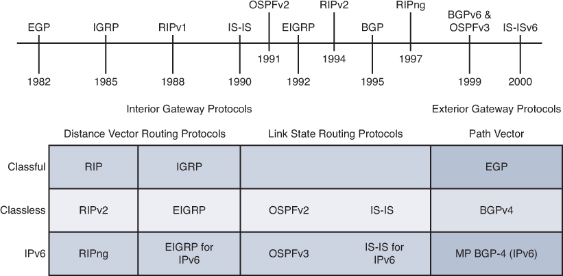
Classifying Dynamic Routing Protocols
Figure 20-2 shows a timeline of IP routing protocols along with a chart that will help you memorize the various ways to classify routing protocols.
Configuration of single-area Open Shortest Path First version 2 (OSPFv2) and single-area OSPFv3 are included in the CCENT exam topics. Configuration of Enhanced Interior Gateway Routing Protocol (EIGRP) for IPv4, EIGRP for IPv6, multiarea OSPFv2, and multiarea OPSFv3 are part of the CCNA exam topics.
Routing protocols can be classified into different groups according to their characteristics:
![]() IGP or EGP
IGP or EGP
![]() Distance vector or link-state
Distance vector or link-state
![]() Classful or classless
Classful or classless
IGP and EGP
An autonomous system (AS) is a collection of routers under a common administration that presents a common, clearly defined routing policy to the Internet. Typical examples are a large company’s internal network and an ISP’s network. Most company networks are not autonomous systems, only a network within their own ISP’s autonomous system. Because the Internet is based on the autonomous system concept, two types of routing protocols are required:
![]() Interior gateway protocols (IGP): Used for intra-AS routing—that is, routing inside an AS
Interior gateway protocols (IGP): Used for intra-AS routing—that is, routing inside an AS
![]() Exterior gateway protocols (EGP): Used for inter-AS routing—that is, routing between autonomous systems
Exterior gateway protocols (EGP): Used for inter-AS routing—that is, routing between autonomous systems
Distance Vector Routing Protocols
Distance vector means that routes are advertised as vectors of distance and direction. Distance is defined in terms of a metric such as hop count, and direction is the next-hop router or exit interface. Distance vector protocols typically use the Bellman-Ford algorithm for the best-path route determination.
Some distance vector protocols periodically send complete routing tables to all connected neighbors. In large networks, these routing updates can become enormous, causing significant traffic on the links.
Although the Bellman-Ford algorithm eventually accumulates enough knowledge to maintain a database of reachable networks, the algorithm does not allow a router to know the exact topology of an internetwork. The router knows only the routing information received from its neighbors.
Distance vector protocols use routers as signposts along the path to the final destination. The only information a router knows about a remote network is the distance or metric to reach that network and which path or interface to use to get there. Distance vector routing protocols do not have an actual map of the network topology.
Distance vector protocols work best in situations where
![]() The network is simple and flat and does not require a hierarchical design.
The network is simple and flat and does not require a hierarchical design.
![]() The administrators do not have enough knowledge to configure and troubleshoot link-state protocols.
The administrators do not have enough knowledge to configure and troubleshoot link-state protocols.
![]() Specific types of networks, such as hub-and-spoke networks, are being implemented.
Specific types of networks, such as hub-and-spoke networks, are being implemented.
![]() Worst-case convergence times in a network are not a concern.
Worst-case convergence times in a network are not a concern.
Link-State Routing Protocols
In contrast to distance vector routing protocol operation, a router configured with a link-state routing protocol can create a “complete view,” or topology, of the network by gathering information from all the other routers. Think of a link-state routing protocol as having a complete map of the network topology. The signposts along the way from source to destination are not necessary because all link-state routers are using an identical “map” of the network. A link-state router uses the link-state information to create a topology map and to select the best path to all destination networks in the topology.
With some distance vector routing protocols, routers send periodic updates of their routing information to their neighbors. Link-state routing protocols do not use periodic updates. After the network has converged, a link-state update is sent only when there is a change in the topology.
Link-state protocols work best in situations where
![]() The network design is hierarchical, usually occurring in large networks.
The network design is hierarchical, usually occurring in large networks.
![]() The administrators have a good knowledge of the implemented link-state routing protocol.
The administrators have a good knowledge of the implemented link-state routing protocol.
![]() Fast convergence of the network is crucial.
Fast convergence of the network is crucial.
Classful Routing Protocols
Classful routing protocols do not send subnet mask information in routing updates. The first routing protocols, such as Routing Information Protocol (RIP), were classful. This was at a time when network addresses were allocated based on classes: Class A, B, or C. A routing protocol did not need to include the subnet mask in the routing update because the network mask could be determined based on the first octet of the network address.
Classful routing protocols can still be used in some of today’s networks, but because they do not include the subnet mask, they cannot be used in all situations. Classful routing protocols cannot be used when a network is subnetted using more than one subnet mask. In other words, classful routing protocols do not support variable-length subnet masking (VLSM).
Other limitations exist to classful routing protocols, including their inability to support discontiguous networks and supernets. Classful routing protocols include Routing Information Protocol version 1 (RIPv1) and Interior Gateway Routing Protocol (IGRP). Neither RIP nor IGRP are included in CCENT or CCNA exam topics.
Classless Routing Protocols
Classless routing protocols include the subnet mask with the network address in routing updates. Today’s networks are no longer allocated based on classes, and the subnet mask cannot be determined by the value of the first octet. Classless routing protocols are required in most networks today because of their support for VLSM and discontiguous networks and supernets. Classless routing protocols are Routing Information Protocol version 2 (RIPv2), Enhanced IGRP (EIGRP), Open Shortest Path First (OSPF), Intermediate System–to–Intermediate System (IS-IS), and Border Gateway Protocol (BGP).
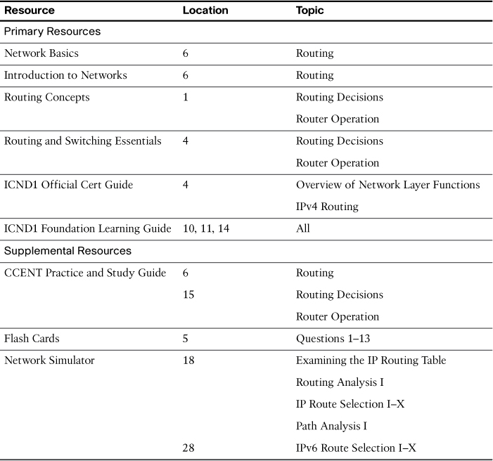
Study Resources
For today’s exam topics, refer to the following resources for more study.