
Day 16. Static and Default Route Configuration
CCENT 100-101 ICND1 Exam Topics
![]() Configure and verify routing configuration for a static or default route given specific routing requirements.
Configure and verify routing configuration for a static or default route given specific routing requirements.
Key Topics
Today we focus on static and default routing for IPv4 and IPv6. Static routes are a common part of an enterprise’s routing policy. Static routes can be used to force traffic to use a specific path or to establish a default route out of the enterprise. Static routes are hard-coded into the routing table by the network administrator. Thus, a network administrator must monitor and maintain static routes to ensure connectivity.
Static and Default Routing Overview
When a router configured with a dynamic routing protocol can learn routes from other routers without any additional input from the network administrator, why would you use static routing? Situations vary and there can be other reasons unique to a particular implementation, but in general:
![]() Use static routes:
Use static routes:
![]() In a small network that requires only simple routing
In a small network that requires only simple routing
![]() In a hub-and-spoke network topology
In a hub-and-spoke network topology
![]() When you want to create a quick ad hoc route
When you want to create a quick ad hoc route
![]() As a backup when there is failure on the primary route
As a backup when there is failure on the primary route
![]() Do not use static routes:
Do not use static routes:
![]() In a large network
In a large network
![]() When the network is expected to scale
When the network is expected to scale
Static routes are commonly used when you are routing from a larger network to a stub network (a network that is accessed by a single link). Static routes can also be useful for specifying a default route or “gateway of last resort.” For example, in Figure 16-1, R2 is attached to a stub network.
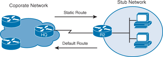
In Figure 16-1, there is no other route out of the stub network except to send packets to HQ. So it makes sense to configure R2 with a default route pointing out the interface attached to HQ. Similarly, there is only one way for HQ to route packets destined for the stub network attached to R2. So it makes sense to configure HQ with a static route pointing out the interface attached to R2. Yes, you could configure both routers with a dynamic routing protocol. But it can introduce a level of complexity that might not be necessary in a stub network situation.
IPv4 Static Route Configuration
To configure a static route, use the ip route command with the following relevant syntax:
Router(config)# ip route network-address subnet-mask {ip-address | exit-interface}}
[administrative-distance]
The explanation for each parameter is as follows:
![]() network-address: The destination network address of the remote network to be added to the routing table.
network-address: The destination network address of the remote network to be added to the routing table.
![]() subnet-mask: The subnet mask of the remote network to be added to the routing table. The subnet mask can be modified to summarize a group of networks.
subnet-mask: The subnet mask of the remote network to be added to the routing table. The subnet mask can be modified to summarize a group of networks.
One or both of the following parameters are used:
![]() ip-address: Commonly referred to as the next-hop router’s IP address
ip-address: Commonly referred to as the next-hop router’s IP address
![]() exit-interface: Outgoing interface that would be used in forwarding packets to the destination network
exit-interface: Outgoing interface that would be used in forwarding packets to the destination network
Also shown is the administrative-distance optional parameter. This is used when configuring a floating static route, as we will see later in today’s review.
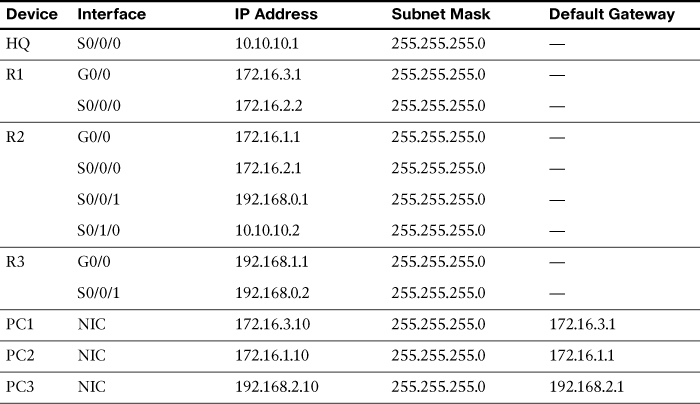
Figure 16-2 shows the topology we will use today to review static and default routing.

Table 16-1 shows the IPv4 addressing scheme we will use with the topology shown in Figure 16-2.
Assume that R1 is configured and knows about its own directly connected networks. Example 16-1 shows the routing table for R1 before any static routing is configured.
Example 16-1 R1 Routing Table Before Static Routes Are Configured
R1# show ip route
<output omitted>
Gateway of last resort is not set
172.16.0.0/16 is variably subnetted, 4 subnets, 2 masks
C 172.16.2.0/24 is directly connected, Serial0/0/0
L 172.16.2.2/32 is directly connected, Serial0/0/0
C 172.16.3.0/24 is directly connected, GigabitEthernet0/0
L 172.16.3.1/32 is directly connected, GigabitEthernet0/0
R1#
The remote networks that R1 does not know about are as follows:
![]() 172.16.1.0/24: The LAN on R2
172.16.1.0/24: The LAN on R2
![]() 192.168.0.0/24: The serial network between R2 and R3
192.168.0.0/24: The serial network between R2 and R3
![]() 192.168.1.0/24: The LAN on R3
192.168.1.0/24: The LAN on R3
![]() 10.10.10.0/24: The serial network between R2 and HQ
10.10.10.0/24: The serial network between R2 and HQ
![]() 0.0.0.0/0: All other networks accessible through HQ
0.0.0.0/0: All other networks accessible through HQ
IPv4 Static Routes Using the “Next-Hop” Parameter
Using the “next-hop” parameter, R1 can be configured with three static routes—one for each of the networks R1 does not yet know about. Example 16-2 shows the command syntax.
Example 16-2 Static Route Configuration with “Next-Hop” Parameter
R1(config)# ip route 172.16.1.0 255.255.255.0 172.16.2.1
R1(config)# ip route 192.168.0.0 255.255.255.0 172.16.2.1
R1(config)# ip route 192.168.1.0 255.255.255.0 172.16.2.1
R1(config)# ip route 10.10.10.0 255.255.255.0 172.16.2.1
The interface that routes to the next hop must be “up” and “up” before the static routes can be entered in the routing table. Example 16-3 verifies that the static routes are now in the routing table.
Example 16-3 R1 Routing Table After Static Routes Are Configured
R1# show ip route
<output omitted>
Gateway of last resort is not set
10.0.0.0/24 is subnetted, 1 subnets
S 10.10.10.0/24 [1/0] via 172.16.2.1
172.16.0.0/16 is variably subnetted, 5 subnets, 2 masks
S 172.16.1.0/24 [1/0] via 172.16.2.1
C 172.16.2.0/24 is directly connected, Serial0/0/0
L 172.16.2.2/32 is directly connected, Serial0/0/0
C 172.16.3.0/24 is directly connected, GigabitEthernet0/0
L 172.16.3.1/32 is directly connected, GigabitEthernet0/0
S 192.168.0.0/24 [1/0] via 172.16.2.1
S 192.168.1.0/24 [1/0] via 172.16.2.1
R1#
With using the next-hop parameter, the router must have a route in the table to the network that the next-hop address belongs to. Highlighted in Example 16-3, we see that R1 does indeed have a route to the 172.16.2.0/24 network, which includes the next-hop address 172.16.2.1. However, configuring a next-hop address requires the router to perform a recursive lookup to find the exit interface before it can send the packet out the Serial 0/0/0 interface.
IPv4 Static Routes Using the Exit Interface Parameter
To avoid a recursive lookup and have a router immediately send packets to the exit interface, configure the static route using the exit-interface parameter instead of the next-hop (ip-address) parameter.
For example, on R2, we can configure static routes to the R1 and R3 LANs by specifying the exit interface:
R2(config)# ip route 172.16.3.0 255.255.255.0 serial 0/0/0
R2(config)# ip route 192.168.1.0 255.255.255.0 serial 0/0/1
Any previous static routes to this network using a next-hop IP address should be removed. R2 now has two static routes in its routing table, as shown in Example 16-4, that it can use immediately to route to the 172.16.3.0/24 and 192.168.1.0/24 networks without having to do a recursive route lookup.
Example 16-4 R2 Routing Table After Static Route Is Configured
R2# show ip route
<output omitted>
Gateway of last resort is not set
10.0.0.0/8 is variably subnetted, 2 subnets, 2 masks
C 10.10.10.0/24 is directly connected, Serial0/1/0
L 10.10.10.2/32 is directly connected, Serial0/1/0
172.16.0.0/16 is variably subnetted, 5 subnets, 2 masks
C 172.16.1.0/24 is directly connected, GigabitEthernet0/0
L 172.16.1.1/32 is directly connected, GigabitEthernet0/0
C 172.16.2.0/24 is directly connected, Serial0/0/0
L 172.16.2.1/32 is directly connected, Serial0/0/0
S 172.16.3.0/24 is directly connected, Serial0/0/0
192.168.0.0/24 is variably subnetted, 2 subnets, 2 masks
C 192.168.0.0/24 is directly connected, Serial0/0/1
L 192.168.0.1/32 is directly connected, Serial0/0/1
S 192.168.1.0/24 is directly connected, Serial0/0/1
R2#
Note
Although the highlighted output in Example 16-4 shows that the routes are “directly connected,” technically that is not true. However, as far as R2 is concerned, the exit interface is the way to get to the destination, much like truly directly connected routes. Another benefit to using the exit interface configuration as opposed to the next-hop address configuration is that the static route does not depend upon the IP address stability of the next hop. Most of the time, using the exit interface configuration is the best practice. And so we will use the exit interface configuration for all static and default routes as we continue with today’s and the remaining days’ reviews.
IPv4 Default Route Configuration
A default route is a special kind of static route used to represent all routes with zero or no bits matching. In other words, when there are no routes that have a more specific match in the routing table, the default route will be a match.
The destination IP address of a packet can match multiple routes in the routing table. For example, consider having the following two static routes in the routing table:
172.16.0.0/24 is subnetted, 3 subnets
S 172.16.1.0 is directly connected, Serial0/0/0
S 172.16.0.0/16 is directly connected, Serial0/0/1
A packet destined for 172.16.1.10, the packet’s destination IP address, matches both routes. However, the 172.16.1.0 route is the more specific route because the destination matches the first 24 bits, whereas the destination matches only the first 16 bits of the 172.16.0.0 route. Therefore, the router will use the route with the most specific match.
A default route is a route that will match all packets. Commonly called a quad-zero route, a default route uses 0.0.0.0 (thus, the term quad-zero) for both the network-address and subnet-mask parameter, as shown in this syntax:
Router(config)# ip route 0.0.0.0 0.0.0.0 {ip-address | exit-interface}
Referring to the topology shown in Figure 16-2, assume that HQ has a connection to the Internet. From the perspective of R2, all default traffic can be sent to HQ for routing outside the domain known to R2.
The following command configures R2 with a default route pointing to HQ:
R2(config)# ip route 0.0.0.0 0.0.0.0 serial 0/1/0
R2 now has a “gateway of last resort” listed in the routing table—a candidate default route indicated by the asterisk (*) next to the S code, as shown in Example 16-5.
Example 16-5 R2 Routing Table After Default Route Is Configured
R2# show ip route
<some codes omitted>
* - candidate default, U - per-user static route, o - ODR
P - periodic downloaded static route
Gateway of last resort is 0.0.0.0 to network 0.0.0.0
10.0.0.0/8 is variably subnetted, 2 subnets, 2 masks
C 10.10.10.0/24 is directly connected, Serial0/1/0
L 10.10.10.2/32 is directly connected, Serial0/1/0
172.16.0.0/16 is variably subnetted, 5 subnets, 2 masks
C 172.16.1.0/24 is directly connected, GigabitEthernet0/0
L 172.16.1.1/32 is directly connected, GigabitEthernet0/0
C 172.16.2.0/24 is directly connected, Serial0/0/0
L 172.16.2.1/32 is directly connected, Serial0/0/0
S 172.16.3.0/24 is directly connected, Serial0/0/0
192.168.0.0/24 is variably subnetted, 2 subnets, 2 masks
C 192.168.0.0/24 is directly connected, Serial0/0/1
L 192.168.0.1/32 is directly connected, Serial0/0/1
S 192.168.1.0/24 is directly connected, Serial0/0/1
S* 0.0.0.0/0 is directly connected, Serial0/1/0
R2#
From R1 and R3’s perspective, R2 is the default route. The following commands configure R1 and R3 with a default route pointing to R2:
R1(config)# ip route 0.0.0.0 0.0.0.0 serial 0/0/0
!
R3(config)# ip route 0.0.0.0 0.0.0.0 serial 0/0/1
Again, we can verify that the default route is now in the routing table for R1, as shown in Example 16-6.
Example 16-6 R1 and R3 Routing Tables After Default Route Is Configured
!R1!!!!!!!!!!!
R1# show ip route
<some codes omitted>
* - candidate default, U - per-user static route, o - ODR
P - periodic downloaded static route
Gateway of last resort is 0.0.0.0 to network 0.0.0.0
172.16.0.0/16 is variably subnetted, 4 subnets, 2 masks
C 172.16.2.0/24 is directly connected, Serial0/0/0
L 172.16.2.2/32 is directly connected, Serial0/0/0
C 172.16.3.0/24 is directly connected, GigabitEthernet0/0
L 172.16.3.1/32 is directly connected, GigabitEthernet0/0
S* 0.0.0.0/0 is directly connected, Serial0/0/0
R1#
!
!R3!!!!!!!!!!!!
R3# show ip route
<some codes omitted>
* - candidate default, U - per-user static route, o - ODR
P - periodic downloaded static route
Gateway of last resort is 0.0.0.0 to network 0.0.0.0
192.168.0.0/24 is variably subnetted, 2 subnets, 2 masks
C 192.168.0.0/24 is directly connected, Serial0/0/1
L 192.168.0.2/32 is directly connected, Serial0/0/1
192.168.1.0/24 is variably subnetted, 2 subnets, 2 masks
C 192.168.1.0/24 is directly connected, GigabitEthernet0/0
L 192.168.1.1/32 is directly connected, GigabitEthernet0/0
S* 0.0.0.0/0 is directly connected, Serial0/0/1
R3#
After evaluating the complete routing tables for R1, R2, and R3 shown in Examples 16-5 and 16-6, you can see that R1 and R3 only need one route out—a default route. R2 acts as a hub router to the R1 and R3 spokes. Therefore, it needs two static routes pointing to the R1 and R3 LANs. R2 also has a route out to HQ for any destinations it does not know about. But what about HQ? Currently, HQ does not have routes back to any of the networks accessible through R2. So any traffic from PC1, PC2, and PC3 is currently confined to the R1, R2, and R3 networks. None of these PCs can ping the HQ interface address 10.10.10.1. In the traceroute output shown in Example 16-7, failure occurs after R2 responds. This is because HQ receives the ICMP requests from PC1 but does not have a route back to the 172.16.3.0/24 network. Therefore, HQ is dropping the packets.
Example 16-7 traceroute from PC1 to HQ Fails
C:> tracert 10.10.10.1
Tracing route to 10.10.10.1 over a maximum of 30 hops:
1 0 ms 0 ms 1 ms 172.16.3.1
2 0 ms 0 ms 1 ms 172.16.2.1
3 * * * Request timed out.
4 ^C
C:>
Let’s configure HQ with static routes to complete the static route configuration for the topology shown in Figure 16-2.
IPv4 Summary Static Route Configuration
Before configuring five separate static routes for each of the networks shown in Figure 16-2, notice that the 172.16 networks can be summarized into one route and that the 192.168 networks can be summarized into one route. We reviewed summary routes on Day 23, “IPv4 Subnetting and VLSM,” so we will not detail the process here. Example 16-8 shows the five routes in binary with the bits in common highlighted.
Example 16-8 Summary Route Calculation for HQ Static Routes
Summary calculation for the 172.16 networks:
10101100.00010000.00000001.00000000
10101100.00010000.00000010.00000000
10101100.00010000.00000011.00000000
Summary calculation for the 192.168 networks:
11000000.10101000.00000000.00000000
11000000.10101000.00000001.00000000
So, the summary route for the 172.16 networks is 172.16.0.0/22 because the three network addresses have 22 bits in common. Although not part of the current addressing scheme, this summary static route would also include the route 172.16.0.0/24. The summary route for the 192.168 networks is 192.168.0.0/23 because the two network addresses have 23 bits in common.
You can now configure HQ with two summary static routes instead of five individual static routes:
HQ(config)# ip route 172.16.0.0 255.255.252.0 serial 0/0/0
HQ(config)# ip route 192.168.0.0 255.255.254.0 Serial0/0/0
Now PC1 can successfully trace a route to the HQ interface, as shown in Example 16-9.
Example 16-9 traceroute from PC1 to HQ Succeeds
C:> tracert 10.10.10.1
Tracing route to 10.10.10.1 over a maximum of 30 hops:
1 1 ms 0 ms 0 ms 172.16.3.1
2 0 ms 1 ms 2 ms 172.16.2.1
3 1 ms 2 ms 1 ms 10.10.10.1
Trace complete.
C:>
The trace is successful because HQ now has a route back to PC1’s network, as shown in Example 16-10.
Example 16-10 HQ Routing Table with IPv4 Summary Static Routes
HQ# show ip route
<output omitted>
Gateway of last resort is not set
10.0.0.0/8 is variably subnetted, 2 subnets, 2 masks
C 10.10.10.0/24 is directly connected, Serial0/0/0
L 10.10.10.1/32 is directly connected, Serial0/0/0
172.16.0.0/22 is subnetted, 1 subnets
S 172.16.0.0/22 is directly connected, Serial0/0/0
S 192.168.0.0/23 is directly connected, Serial0/0/
HQ#
IPv6 Static Routing
Static routing with IPv6 is very similar to IPv4. We will use the same topology but change the addressing to IPv6, as shown in Figure 16-3.
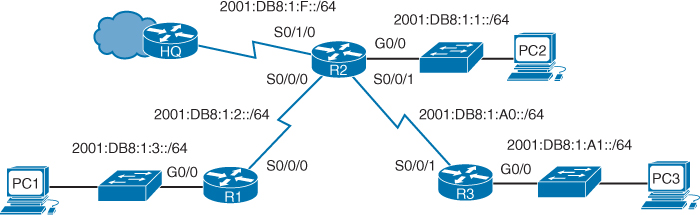
Table 16-2 shows the IPv6 addressing scheme we will use with the topology shown in Figure 16-3.
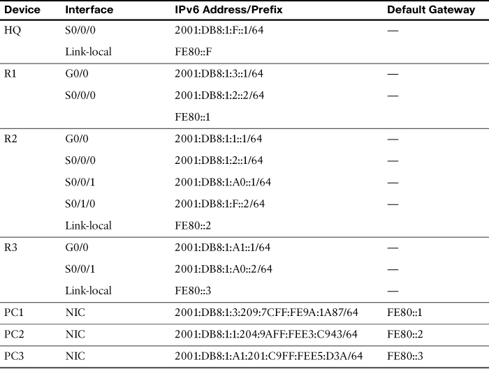
Note
The IPv6 addressing for the PCs is set to autoconfiguration. Pinging from PC to PC would not really be much fun. However, the IPv6 addresses are not manually set so that you can practice your knowledge of how EUI-64 works. Can you figure out what the MAC address is for each PC? If not, review Day 21, “Implementing IPv6 Addressing.” (Hint: FFFE and flip the bit.) Then, if you are following along using a simulator, you might want to consider manually configuring the PCs with easier IPv6 addresses—2001:DB8:1:3::A/64 on PC1, for example. This will greatly improve your pinging experience.
Router(config)# ipv6 route ipv6-prefix/prefix-length {ipv6-address | exit-interface}
[administrative-distance]
Therefore, the following commands would configure R2 with static routes to the R1 and R3 LANs:
R2(config)# ipv6 route 2001:DB8:1:3::/64 Serial0/0/0
R2(config)# ipv6 route 2001:DB8:1:A1::/64 Serial0/0/1
As highlighted in the output from the show ipv6 route command shown in Example 16-11, R2 now has routes in the routing table to the R1 and R3 LANs.
Example 16-11 R2 IPv6 Routing Table After Static Routes Are Configured
R2# show ipv6 route
IPv6 Routing Table - 11 entries
<code output omitted>
C 2001:DB8:1:1::/64 [0/0]
via ::, GigabitEthernet0/0
L 2001:DB8:1:1::1/128 [0/0]
via ::, GigabitEthernet0/0
C 2001:DB8:1:2::/64 [0/0]
via ::, Serial0/0/0
L 2001:DB8:1:2::1/128 [0/0]
via ::, Serial0/0/0
S 2001:DB8:1:3::/64 [1/0]
via ::, Serial0/0/0
C 2001:DB8:1:F::/64 [0/0]
via ::, Serial0/1/0
L 2001:DB8:1:F::2/128 [0/0]
via ::, Serial0/1/0
C 2001:DB8:1:A0::/64 [0/0]
via ::, Serial0/0/1
L 2001:DB8:1:A0::1/128 [0/0]
via ::, Serial0/0/1
S 2001:DB8:1:A1::/64 [1/0]
via ::, Serial0/0/1
L FF00::/8 [0/0]
via ::, Null0
Router(config)# ipv6 route ::/0 {ipv6-address | exit-interface}
Just like the quad-zero in IPv4, the double colon (::) means all 0s or any address and the /0 means any prefix length.
Continuing with our example in Figure 16-3, we would configure R1, R2, and R3 with the following default routes:
R1(config)# ipv6 route ::/0 serial 0/0/0
R2(config)# ipv6 route ::/0 serial 0/1/0
R3(config)# ipv6 route ::/0 serial 0/0/1
The highlights in Example 16-12 show the default routes for R1, R2, and R3.
Example 16-12 Default Routes in the Routing Tables for R1, R2, and R3
!R1!!!!!!!!!!!
R1# show ipv6 route
IPv6 Routing Table - 6 entries
<code output omitted>
S ::/0 [1/0]
via ::, Serial0/0/0
<output for connected and local routes omitted>
!R2!!!!!!!!!!!
R2# show ipv6 route
IPv6 Routing Table - 12 entries
<code output omitted>
S ::/0 [1/0]
via ::, Serial0/1/0
S 2001:DB8:1:3::/64 [1/0]
via ::, Serial0/0/0
S 2001:DB8:1:A1::/64 [1/0]
via ::, Serial0/0/1
<output for connected and local routes omitted>
!R3!!!!!!!!!!!
R3# show ipv6 route
IPv6 Routing Table - 6 entries
<code output omitted>
S ::/0 [1/0]
via ::, Serial0/0/1
<output for connected and local routes omitted>
IPv6 Summary Static Route Configuration
Similar to the IPv4 static routing scenario, HQ can be configured with two summary static routes to the R1, R2, and R3 LANs. Example 16-13 shows the first four hextet (64 bits) of the five routes in binary with the bits in common highlighted.
Example 16-13 Summary Route Calculation for HQ Static Routes
Summary calculation for the first four hextets of 2001:DB8:1:1::/64,
2001:DB8:1:2::/64, and 2001:DB8:1:3::/64 networks:
0010000000000001:0000110110111000:0000000000000001: 0000000000000001:<4 all-0s
hextets>
0010000000000001:0000110110111000:0000000000000001: 0000000000000010:<4 all-0s
hextets>
0010000000000001:0000110110111000:0000000000000001: 0000000000000011:<4 all-0s
hextets>
Summary calculation for the first four hextets of 2001:DB8:1:A0::/64 and
2001:DB8:1:A1::/64 networks:
0010000000000001:0000110110111000:0000000000000001: 000000001010 0000:<4 all-0s
hextets>
0010000000000001:0000110110111000:0000000000000001: 000000001010 0001:<4 all-0s
hextets>
So, the first summary route is 2001:DB8:1::/62 because the three network addresses have 62 bits in common. Although not part of the current addressing scheme, this summary static route would also include the network 2001:DB8:1::/64. The second summary route is 2001:DB8:1:A0::/63 because the two network addresses have 63 bits in common.
You can now configure HQ with the following two summary static routes:
HQ(config)# ipv6 route 2001:DB8:1::/62 Serial0/0/0
HQ(config)# ipv6 route 2001:DB8:1:A0::/63 Serial0/0/0
Now HQ has two summary routes, as shown in the highlighted entries in Example 16-14.
Example 16-14 HQ Routing Table with IPv6 Summary Static Routes
HQ# show ipv6 route
IPv6 Routing Table - 5 entries
<output omitted>
S 2001:DB8:1::/62 [1/0]
via ::, Serial0/0/0
C 2001:DB8:1:F::/64 [0/0]
via ::, Serial0/0/0
L 2001:DB8:1:F::1/128 [0/0]
via ::, Serial0/0/0
S 2001:DB8:1:A0::/63 [1/0]
via ::, Serial0/0/0
L FF00::/8 [0/0]
via ::, Null0
HQ#
Study Resources
For today’s exam topics, refer to the following resources for more study.
