Day 2. Troubleshoot Layer 1 Issues
CCENT 100-101 ICND1 Exam Topics
![]() Troubleshoot and resolve Layer 1 problems.
Troubleshoot and resolve Layer 1 problems.
Key Topics
We finish the troubleshooting section with Layer 1. The physical layer is often the reason a network issue exists—power outages, disconnected cables, power cycled devices, hardware failures, and so on. So let’s look at some of the troubleshooting tools available to you, in addition to actually walking over to the wiring closet or network device and “physically” checking Layer 1.
Media Issues
Besides failing hardware, other common physical layer issue occurs with media. The following are a few examples:
![]() New equipment is installed that introduces new electromagnetic interference (EMI) sources into the environment.
New equipment is installed that introduces new electromagnetic interference (EMI) sources into the environment.
![]() Cable runs too close to powerful motors, like an elevator.
Cable runs too close to powerful motors, like an elevator.
![]() Poor cable management puts a strain on some RJ-45 connectors, causing one or more wires to break.
Poor cable management puts a strain on some RJ-45 connectors, causing one or more wires to break.
![]() New applications change traffic patterns.
New applications change traffic patterns.
![]() When new equipment is connected to a switch, the connection operates in a half-duplex mode or a duplex mismatch occurs, which could lead to an excessive number of collisions.
When new equipment is connected to a switch, the connection operates in a half-duplex mode or a duplex mismatch occurs, which could lead to an excessive number of collisions.
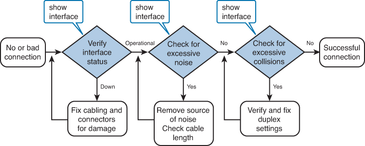
Figure 2-1 shows an excellent troubleshooting flowchart that you can use to aid in troubleshooting switch media issues.
Let’s look at the output from the show interface and show interface status commands.
Interface Status and the Switch Configuration
Because today we are focusing on switch troubleshooting, let’s look at the show commands that are helpful in troubleshooting your basic configuration.
Interface Status Codes
In general, interfaces are either “up” or “down.” However, when an interface is down and you don’t know why, the code in the show interfaces command provides more information to help you determine the reason. Table 2-1 lists the code combinations and some possible causes for the status indicated.

Duplex and Speed Mismatches
One of the more common problems is issues with speed and/or duplex mismatches. On switches and routers, the speed {10 | 100 | 1000} interface subcommand and the duplex {half | full} interface subcommand set these values. Note that configuring both speed and duplex on a switch interface disables the IEEE-standard autonegotiation process on that interface.
The show interface status and show interface commands list both the speed and duplex settings on an interface, as shown in Example 2-1.
Example 2-1 Commands to Verify Speed and Duplex Settings
S1# show interface status
Port Name Status Vlan Duplex Speed Type
Fa0/1 connected trunk full 100 10/100BaseTX
Fa0/2 connected 1 half 100 10/100BaseTX
Fa0/3 connected 1 a-full a-100 10/100BaseTX
Fa0/4 disabled 1 auto auto 10/100BaseTX
Fa0/5 disabled 1 auto auto 10/100BaseTX
Fa0/6 notconnect 1 auto auto 10/100BaseTX
!Remaining output omitted
S1# show interface fa0/3
FastEthernet0/1 is up, line protocol is up (connected)
Hardware is Fast Ethernet, address is 001b.5302.4e81 (bia 001b.5302.4e81)
MTU 1500 bytes, BW 100000 Kbit, DLY 100 usec,
reliability 255/255, txload 1/255, rxload 1/255
Encapsulation ARPA, loopback not set
Keepalive set (10 sec)
Full-duplex, 100Mb/s, media type is 10/100BaseTX
input flow-control is off, output flow-control is unsupported
ARP type: ARPA, ARP Timeout 04:00:00
Last input never, output 00:00:00, output hang never
Last clearing of "show interface" counters never
Input queue: 0/75/0/0 (size/max/drops/flushes); Total output drops: 0
Queueing strategy: fifo
Output queue: 0/40 (size/max)
5 minute input rate 1000 bits/sec, 1 packets/sec
5 minute output rate 0 bits/sec, 0 packets/sec
2745 packets input, 330885 bytes, 0 no buffer
Received 1386 broadcasts (0 multicast)
0 runts, 0 giants, 0 throttles
0 input errors, 0 CRC, 0 frame, 0 overrun, 0 ignored
0 watchdog, 425 multicast, 0 pause input
0 input packets with dribble condition detected
56989 packets output, 4125809 bytes, 0 underruns
0 output errors, 0 collisions, 1 interface resets
0 babbles, 0 late collision, 0 deferred
0 lost carrier, 0 no carrier, 0 PAUSE output
0 output buffer failures, 0 output buffers swapped out
Notice that both commands will show the duplex and speed settings of the interface. However, the show interface status command is preferred for troubleshooting duplex or speed mismatches because it shows exactly how the switch determined the duplex and speed of the interface. In the duplex column, a-full means that the switch autonegotiated full duplex. The setting full or half means that the switch was configured at that duplex setting. Autonegotiation has been disabled. In the speed column, a-100 means that the switch autonegotiated 100Mbps as the speed. The setting 10 or 100 means that the switch was configured at that speed setting.
Finding a duplex mismatch can be much more difficult than finding a speed mismatch because, if the duplex settings do not match on the ends of an Ethernet segment, the switch interface will still be in a connect (up/up) state. In this case, the interface works, but the network might work poorly, with hosts experiencing poor performance and intermittent communication problems. To identify duplex mismatch problems, check the duplex setting on each end of the link and watch for incrementing collision and late collision counters.
Common Layer 1 Problems On “Up” Interfaces
When a switch interface is “up,” it does not necessarily mean that the interface is operating in an optimal state. For this reason, IOS will track certain counters to help identify problems that can occur even though the interface is in a connect state. These counters are highlighted in the output in Example 2-1. Table 2-2 summarizes three general types of Layer 1 interface problems that can occur while an interface is in the up, connected state.

CDP as a Troubleshooting Tool
CDP discovers basic information about directly connected Cisco routers and switches by sending CDP messages. Example 2-2 shows the output from a switch that is directly connected to a Cisco router.
Example 2-2 Output from the show cdp Commands
S1# show cdp ?
entry Information for specific neighbor entry
interface CDP interface status and configuration
neighbors CDP neighbor entries
traffic CDP statistics
| Output modifiers
<cr>
S1# show cdp neighbors
Capability Codes: R - Router, T - Trans Bridge, B - Source Route Bridge
S - Switch, H - Host, I - IGMP, r - Repeater, P - Phone
Device ID Local Intrfce Holdtme Capability Platform Port ID
R1 Fas 0/3 124 R S I 1841 Fas 0/0
S1# show cdp neighbors detail
-------------------------
Device ID: R1
Entry address(es):
IP address: 192.168.1.1
Platform: Cisco 1841, Capabilities: Router Switch IGMP
Interface: FastEthernet0/3, Port ID (outgoing port): FastEthernet0/0
Holdtime : 175 sec
Version :
Cisco IOS Software, 1841 Software (C1841-ADVIPSERVICESK9-M), Version 12.4(10b), RELEASE SO
FTWARE (fc3)
Technical Support: http://www.cisco.com/techsupport
Copyright (c) 1986-2007 by Cisco Systems, Inc.
Compiled Fri 19-Jan-07 15:15 by prod_rel_team
advertisement version: 2
VTP Management Domain: ''
Duplex: full
Management address(es):
S1# show cdp
Global CDP information:
Sending CDP packets every 60 seconds
Sending a holdtime value of 180 seconds
Sending CDPv2 advertisements is enabled
S1# show cdp interface
FastEthernet0/1 is up, line protocol is up
Encapsulation ARPA
Sending CDP packets every 60 seconds
Holdtime is 180 seconds
FastEthernet0/2 is down, line protocol is down
Encapsulation ARPA
Sending CDP packets every 60 seconds
Holdtime is 180 seconds
!
!Output is same for interface Fa0/3 through Gi0/1
!
GigabitEthernet0/2 is down, line protocol is down
Encapsulation ARPA
Sending CDP packets every 60 seconds
Holdtime is 180 seconds
S1#
The show cdp neighbors detail output displays CDP messages that contain the following useful information:
![]() Device ID: Typically the hostname
Device ID: Typically the hostname
![]() Entry address(es): Network and data-link addresses
Entry address(es): Network and data-link addresses
![]() Platform: The model and OS level running in the device
Platform: The model and OS level running in the device
![]() Capabilities: Information on what type of device it is (for example, a router or a switch)
Capabilities: Information on what type of device it is (for example, a router or a switch)
![]() Interface: The interface on the router or switch issuing the show cdp command with which the neighbor was discovered
Interface: The interface on the router or switch issuing the show cdp command with which the neighbor was discovered
![]() Port ID: Text that identifies the port used by the neighboring device to send CDP messages to the local device
Port ID: Text that identifies the port used by the neighboring device to send CDP messages to the local device
Also notice in the show cdp interface command that every interface on the switch is sending CDP messages every 60 seconds. CDP is enabled by default and thus creates a security issue because CDP messages can be intercepted and network information discovered. CDP can easily be disabled both globally for the entire device (no cdp run) or individually by interface (no cdp enable).