Day 14. Single-Area OSPFv3
CCENT 100-101 ICND1 Exam Topics
![]() Configure and verify OSPF (single-area).
Configure and verify OSPF (single-area).
Key Topics
Today we review the differences between OSPFv2 and OSPFv3. Then we review the commands necessary to configure and verify an OSPFv3 implementation. The review content for the day is light. So this is a good day to practice configuring OSPFv2 and OSPFv3, possibly dual-stacking them on the same topology so that you can easily compare the two.
OSPFv2 Versus OSPFv3
In 1999, OSPFv3 for IPv6 was published in RFC 2740. In 2008, OSPFv3 was updated in RFC 5340 as OSPF for IPv6. However, it’s still referred to as OSPFv3.
OSPFv3 has the same functionality as OSPFv2 but uses IPv6 as the network layer transport, communicating with OSPFv3 peers and advertising IPv6 routes. OSPFv3 also uses the shortest path first (SPF) algorithm as the computation engine to determine the best paths throughout the routing domain.
As with all IPv6 routing protocols, OSPFv3 has separate processes from its IPv4 counterpart. OSPFv2 and OSPFv3 each have separate adjacency tables, OSPF topology tables, and IP routing tables.
Similarities Between OSPFv2 and OSPFv3
OSPFv3 operates very much like OSPFv2. Table 14-1 summarizes the operational features that OSPFv2 and OSPFv3 share in common.

Differences Between OSPFv2 and OSPFv3
The major differences between OSPFv2 and OSPFv3 are listed in Table 14-2.

Single-Area OSPFv3 Configuration
OSPFv3 configuration requires the same basic steps as OSPFv2: pick and configure a process ID, and enable the process on each interface, while assigning the correct OSPF area to each interface. However, the way in which these steps are implemented is quite different.
Figure 14-1 shows the topology we will use to review the OSPFv3 configuration steps.
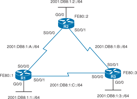
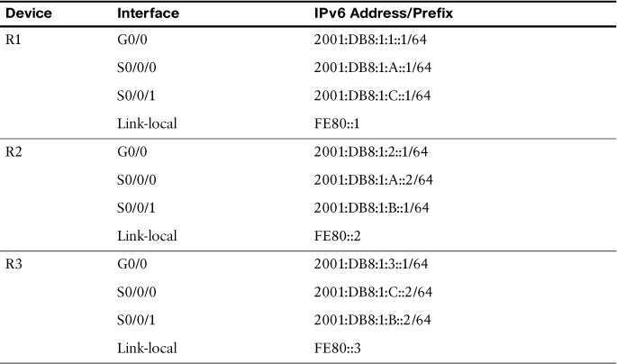
To ease our configuration and verification steps, we will use the simplified IPv6 addressing scheme shown in Table 14-3.
1. If the router-id command is configured, use the manually configured IPv4 router ID.
2. If the router ID is not configured, use the highest configured loopback interface IPv4 address.
3. If no loopback IPv4 address is configured, use the highest configured interface IPv4 address. The interface can be either in the up/up state or the up/down state.
Also like OSPFv2, you configure the router ID with the router-id command in router configuration mode. However, notice that both OSPFv2 and OSPFv3 use an IPv4 address for the router ID. This means that, before a router can start an OSPFv3 routing process, there must be an IPv4 address configured—either an interface or a router ID. If not, the router will return the following syslog message when you attempt to enable the OSPFv3 routing process with the ipv6 router ospf command:
R1(config)# ipv6 router ospf 10
*Jun 3 13:06:06.579: %OSPFv3-4-NORTRID: Process OSPFv3-10-IPv6 could not pick a
router-id, please configure manually
So the next step on R1 is to configure the router ID. It can be any IPv4 address. For simplicity, we will use 1.1.1.1:
R1(config-rtr)# router-id 1.1.1.1
To make sure that costs are accurately calculated for the Gigabit interfaces, we will change the reference bandwidth to 1,000,000,000 bps or 1000 Mbps, with the auto-cost reference-bandwidth command:
R1(config-rtr)# auto-cost reference-bandwidth 1000
% OSPFv3-10-IPv6: Reference bandwidth is changed.
Please ensure reference bandwidth is consistent across all routers.
A syslog message reminds us to do this on every router. Like OSPFv2, we can stop sending updates out the GigabitEthernet 0/0 interface with the passive-interface command:
R1(config-rtr)# passive-interface g0/0
That’s it for router configuration commands. Next, we simply enable OSPFv3 on each of the active interfaces as shown in Example 14-1.
Example 14-1 Enable OSPFv3 on Interfaces
R1(config-rtr)# exit
R1(config)# interface GigabitEthernet 0/0
R1(config-if)# ipv6 ospf 10 area 0
R1(config-if)# interface Serial0/0/0
R1(config-if)# ipv6 ospf 10 area 0
R1(config-if)# interface Serial0/0/1
R1(config-if)# ipv6 ospf 10 area 0
Configure R2 and R3 with similar commands (we can use 2.2.2.2 and 3.3.3.3 for R2 and R3, respectively), and OSPFv3 is fully operational.
Verifying OSPFv3
Wendell Odom, in his book Cisco CCENT/CCNA ICND1 100-101 Official Cert Guide, uses a table (repeated as Table 14-4 here) to summarize the verification commands for both OSPFv2 and OSPFv3. Notice that every OSPFv2 command shown is also available for OSPFv3—just substitute ipv6 for ip.
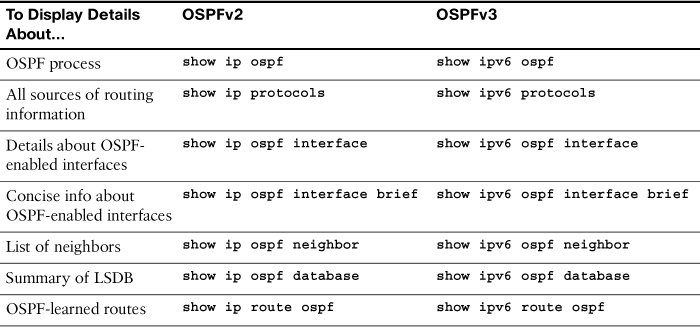
Examples 14-2–14-8 show the output from R1 for the OSPFv3 verification commands shown in Table 14-4.
Example 14-2 Verify the OSPF Process
R1# show ipv6 ospf
Routing Process "ospfv3 10" with ID 1.1.1.1
Event-log enabled, Maximum number of events: 1000, Mode: cyclic
Router is not originating router-LSAs with maximum metric
Initial SPF schedule delay 5000 msecs
Minimum hold time between two consecutive SPFs 10000 msecs
Maximum wait time between two consecutive SPFs 10000 msecs
Minimum LSA interval 5 secs
Minimum LSA arrival 1000 msecs
LSA group pacing timer 240 secs
Interface flood pacing timer 33 msecs
Retransmission pacing timer 66 msecs
Number of external LSA 0. Checksum Sum 0x000000
Number of areas in this router is 1. 1 normal 0 stub 0 nssa
Graceful restart helper support enabled
Reference bandwidth unit is 1000 mbps
RFC1583 compatibility enabled
Area BACKBONE(0)
Number of interfaces in this area is 3
SPF algorithm executed 4 times
Number of LSA 11. Checksum Sum 0x05AD44
Number of DCbitless LSA 0
Number of indication LSA 0
Number of DoNotAge LSA 0
Flood list length 0
R1#
Example 14-3 Verify Sources of Routing Information
R1# show ipv6 protocols
IPv6 Routing Protocol is "connected"
IPv6 Routing Protocol is "ND"
IPv6 Routing Protocol is "ospf 10"
Router ID 1.1.1.1
Number of areas: 1 normal, 0 stub, 0 nssa
Interfaces (Area 0):
Serial0/0/1
Serial0/0/0
GigabitEthernet0/0
Redistribution:
None
R1#
Example 14-4 Verify Details of an OSPF-Enabled Interface
R1# show ipv6 ospf interface serial 0/0/0
Serial0/0/0 is up, line protocol is up
Link Local Address FE80::1, Interface ID 6
Area 0, Process ID 10, Instance ID 0, Router ID 1.1.1.1
Network Type POINT_TO_POINT, Cost: 647
Transmit Delay is 1 sec, State POINT_TO_POINT
Timer intervals configured, Hello 10, Dead 40, Wait 40, Retransmit 5
Hello due in 00:00:07
Graceful restart helper support enabled
Index 1/2/2, flood queue length 0
Next 0x0(0)/0x0(0)/0x0(0)
Last flood scan length is 3, maximum is 3
Last flood scan time is 0 msec, maximum is 0 msec
Neighbor Count is 1, Adjacent neighbor count is 1
Adjacent with neighbor 2.2.2.2
Suppress hello for 0 neighbor(s)
R1#
Example 14-5 Verify OSPF Interface Status
R1# show ipv6 ospf interface brief
Interface PID Area Intf ID Cost State Nbrs F/C
Se0/0/1 10 0 7 647 P2P 1/1
Se0/0/0 10 0 6 647 P2P 1/1
Gi0/0 10 0 3 100 DR 0/0
R1#
Example 14-6 Verify OSPF Neighbor Table
R1# show ipv6 ospf neighbor
OSPFv3 Router with ID (1.1.1.1) (Process ID 10)
Neighbor ID Pri State Dead Time Interface ID Interface
3.3.3.3 0 FULL/ - 00:00:31 6 Serial0/0/1
2.2.2.2 0 FULL/ - 00:00:38 6 Serial0/0/0
R1#
Example 14-7 Verify the OSPF Link-State Database
R1# show ipv6 ospf database
OSPFv3 Router with ID (1.1.1.1) (Process ID 10)
Router Link States (Area 0)
ADV Router Age Seq# Fragment ID Link count Bits
1.1.1.1 1042 0x80000004 0 2 None
2.2.2.2 1264 0x80000002 0 2 None
3.3.3.3 1260 0x80000002 0 2 None
Link (Type-8) Link States (Area 0)
ADV Router Age Seq# Link ID Interface
1.1.1.1 1042 0x80000002 7 Se0/0/1
3.3.3.3 1265 0x80000001 6 Se0/0/1
1.1.1.1 1042 0x80000002 6 Se0/0/0
2.2.2.2 1313 0x80000001 6 Se0/0/0
1.1.1.1 1042 0x80000002 3 Gi0/0
Intra Area Prefix Link States (Area 0)
ADV Router Age Seq# Link ID Ref-lstype Ref-LSID
1.1.1.1 1042 0x80000003 0 0x2001 0
2.2.2.2 1308 0x80000002 0 0x2001 0
3.3.3.3 1260 0x80000002 0 0x2001 0
R1#
Example 14-8 Verify OSPF Routes in the Routing Table
R1# show ipv6 route ospf
IPv6 Routing Table - default - 10 entries
<output omitted>
O 2001:DB8:1:2::/64 [110/747]
via FE80::2, Serial0/0/0
O 2001:DB8:1:3::/64 [110/747]
via FE80::3, Serial0/0/1
O 2001:DB8:1:B::/64 [110/1294]
via FE80::2, Serial0/0/0
via FE80::3, Serial0/0/1
R1#
Study Resources
For today’s exam topics, refer to the following resources for more study.
