Day 28. Switching Concepts and Operation
CCENT 100-101 ICND1 Exam Topics
![]() Identify basic switching concepts and the operation of Cisco switches.
Identify basic switching concepts and the operation of Cisco switches.
Key Topics
Today we review the concepts behind switching, including the history of the development of switching, how switching actually works, as well as the variety of switch features. We also review how to access Cisco devices, the basic IOS commands to navigate the command-line interface (CLI), and the details of how configuration files are managed.
Evolution to Switching
Today’s LANs almost exclusively use switches to interconnect end devices; however, this was not always the case. Initially, devices were connected to a physical bus—a long run of coaxial backbone cabling. With the introduction of 10BASE-T and UTP cabling, the hub gained popularity as a cheaper, easier way to connect devices. But even 10BASE-T with hubs had the following limitations:
![]() A frame being sent from one device can collide with a frame sent by another device attached to that LAN segment. Devices were in the same collision domain sharing the bandwidth.
A frame being sent from one device can collide with a frame sent by another device attached to that LAN segment. Devices were in the same collision domain sharing the bandwidth.
![]() Broadcasts sent by one device were heard by, and processed by, all other devices on the LAN. Devices were in the same broadcast domain. Similar to hubs, switches forward broadcast frames out all ports except for the incoming port. Switch ports can be configured on various VLANs, which will segment them into broadcast domains.
Broadcasts sent by one device were heard by, and processed by, all other devices on the LAN. Devices were in the same broadcast domain. Similar to hubs, switches forward broadcast frames out all ports except for the incoming port. Switch ports can be configured on various VLANs, which will segment them into broadcast domains.
Ethernet bridges were soon developed to solve some of the inherent problems in a shared LAN. A bridge basically segmented a LAN into two collision domains which
![]() Reduced the number of collisions that occurred in a LAN segment
Reduced the number of collisions that occurred in a LAN segment
![]() Increased the available bandwidth
Increased the available bandwidth
When switches arrived on the scene, these devices provided the same benefits of bridges, as well as the following:
![]() A larger number of interfaces to break up the collision domain into more segments
A larger number of interfaces to break up the collision domain into more segments
![]() Hardware-based switching instead of using software to make the decision
Hardware-based switching instead of using software to make the decision
In a LAN where all nodes are connected directly to the switch, the throughput of the network increases dramatically. With each computer connected to a separate port on the switch, each is in a separate collision domain and has its own dedicated segment. The three primary reasons for this increase are as follows:
![]() Dedicated bandwidth to each port
Dedicated bandwidth to each port
![]() Collision-free environment
Collision-free environment
![]() Full-duplex operation
Full-duplex operation
Switching Logic
Ethernet switches selectively forward individual frames from a receiving port to the port where the destination node is connected. During this instant, the switch creates a full-bandwidth, logical, point-to-point connection between the two nodes.
Switches create this logical connection based on the source and destination Media Access Control (MAC) addresses in the Ethernet header. Specifically, the primary job of a LAN switch is to receive Ethernet frames and then make a decision: either forward the frame or ignore the frame. To accomplish this, the switch performs three actions:
1. Decides when to forward a frame or when to filter (not forward) a frame, based on the destination MAC address
2. Learns MAC addresses by examining the source MAC address of each frame received by the switch
3. Creates a (Layer 2) loop-free environment with other switches by using Spanning Tree Protocol (STP)
To make the forward or filter decision, the switch uses a dynamically built MAC address table stored in RAM. By comparing the frame’s destination MAC address with the fields in the table, the switch decides how to forward and/or filter the frame.
For example, in Figure 28-1, the switch receives a frame from Host A with the destination MAC address OC. The switch looks in its MAC table and finds an entry for the MAC address and forwards the frame out port 6. The switch also filters the frame by not forwarding it out any other port, including the port on which the frame was received.

In addition to forwarding and filtering frames, the switch will also refresh the timestamp for the source MAC address of the frame. In Figure 28-1, the MAC address for Host A, OA, is already in the MAC table. So the switch refreshes the entry. Entries that are not refreshed will eventually be removed (after the default 300 seconds in Cisco IOS).
Continuing the example in Figure 28-1, assume that another device, Host E, is attached to port 10. Host B then sends a frame to the new Host E. The switch does not yet know where Host E is located. So it forwards the frame out all active ports except for the port on which the frame was received. The new Host E will receive the frame. When it replies to Host B, the switch will learn Host E’s MAC address and port for the first time and store it in the MAC address table. Subsequent frames destined for Host E will only be sent out port 10.
Finally, LAN switches must have a method for creating a loop-free path for frames to take within the LAN. STP provides loop prevention in Ethernet networks where redundant physical links exist.
Collision and Broadcast Domains
A collision domain is the set of LAN interfaces whose frames could collide with each other. All shared media environments, such as those created by using hubs, are collision domains. When one host is attached to a switch port, the switch creates a dedicated connection, thereby eliminating the potential for a collision. Switches reduce collisions and improve bandwidth use on network segments because they provide dedicated bandwidth to each network segment.
Out of the box, however, a switch cannot provide relief from broadcast traffic. A collection of connected switches forms one large broadcast domain. If a frame with the destination address FFFF.FFFF.FFFF crosses a switch port, that switch must then flood the frame out all other active ports. Each attached device must then process the broadcast frame at least up to the network layer. Routers and VLANs are used to segment broadcast domains. Day 26, “VLAN Concepts,” reviews the use of VLANs to segment broadcast domains.
Frame Forwarding
Switches operate in several ways to forward frames. They can differ in forwarding methods, port speeds, memory buffering, and the OSI layers used to make the forwarding decision. The sections that follow discuss these concepts in greater detail.
Switch Forwarding Methods
Switches use one of the following forwarding methods for switching data between network ports:
![]() Store-and-forward switching: The switch stores received frames in its buffers, analyzes each frame for information about the destination, and evaluates the data integrity using the cyclic redundancy check (CRC) in the frame trailer. The entire frame is stored and the CRC calculated before any of the frame is forwarded. If the CRC passes, the frame is forwarded to the destination.
Store-and-forward switching: The switch stores received frames in its buffers, analyzes each frame for information about the destination, and evaluates the data integrity using the cyclic redundancy check (CRC) in the frame trailer. The entire frame is stored and the CRC calculated before any of the frame is forwarded. If the CRC passes, the frame is forwarded to the destination.
![]() Cut-through switching: The switch buffers just enough of the frame to read the destination MAC address so that it can determine to which port to forward the data. After the switch determines whether there is a match between the destination MAC address and an entry in the MAC address table, the frame is forwarded out the appropriate port(s). This happens as the rest of the initial frame is still being received. The switch does not perform any error checking on the frame.
Cut-through switching: The switch buffers just enough of the frame to read the destination MAC address so that it can determine to which port to forward the data. After the switch determines whether there is a match between the destination MAC address and an entry in the MAC address table, the frame is forwarded out the appropriate port(s). This happens as the rest of the initial frame is still being received. The switch does not perform any error checking on the frame.
![]() Fragment free: The switch waits for the collision window (64 bytes) to pass before forwarding the frame. This means that each frame will be checked into the data field to make sure that no fragmentation has occurred. Fragment free mode provides better error checking than cut-through, with practically no increase in latency.
Fragment free: The switch waits for the collision window (64 bytes) to pass before forwarding the frame. This means that each frame will be checked into the data field to make sure that no fragmentation has occurred. Fragment free mode provides better error checking than cut-through, with practically no increase in latency.
Symmetric and Asymmetric Switching
Symmetric switching provides switched connections between ports with the same bandwidth, such as all 100Mbps ports or all 1000Mbps ports. An asymmetric LAN switch provides switched connections between ports of unlike bandwidth, such as a combination of 10Mbps, 100Mbps, and 1000Mbps ports.
Memory Buffering
Switches store frames for a brief time in a memory buffer. There are two methods of memory buffering:
![]() Port-based memory: Frames are stored in queues that are linked to specific incoming ports.
Port-based memory: Frames are stored in queues that are linked to specific incoming ports.
![]() Shared memory: Frames are deposited into a common memory buffer, which all ports on the switch share.
Shared memory: Frames are deposited into a common memory buffer, which all ports on the switch share.
Layer 2 and Layer 3 Switching
A Layer 2 LAN switch performs switching and filtering based only on MAC addresses. A Layer 2 switch is completely transparent to network protocols and user applications. A Layer 3 switch functions similarly to a Layer 2 switch. But instead of using only the Layer 2 MAC address information for forwarding decisions, a Layer 3 switch can also use IP address information. Layer 3 switches are also capable of performing Layer 3 routing functions, reducing the need for dedicated routers on a LAN. Because Layer 3 switches have specialized switching hardware, they can typically route data as quickly as they can switch data.
Accessing and Navigating the Cisco IOS
By now, you are very familiar with connecting to Cisco devices and configuring them using the command-line interface (CLI). Here, we quickly review methods for accessing and navigating the CLI.
Connecting to Cisco Devices
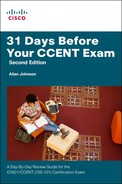
You can access a device directly or from a remote location. Figure 28-2 shows the many ways that you can connect to Cisco devices.
The two ways to configure Cisco devices are as follows:
![]() Console terminal: Use an RJ-45–to–RJ-45 rollover cable and a computer with the terminal communications software (such as HyperTerminal, Tera Term, and so on) to establish a direct connection. Optionally, you can connect a mini-USB cable to the mini-USB console port, if available.
Console terminal: Use an RJ-45–to–RJ-45 rollover cable and a computer with the terminal communications software (such as HyperTerminal, Tera Term, and so on) to establish a direct connection. Optionally, you can connect a mini-USB cable to the mini-USB console port, if available.
![]() Remote terminal: Use an external modem connected to the auxiliary port—routers only—to remotely configure the device.
Remote terminal: Use an external modem connected to the auxiliary port—routers only—to remotely configure the device.
After it is configured, you can access the device using three additional methods:
![]() Establish a terminal (vty) session using Telnet.
Establish a terminal (vty) session using Telnet.
![]() Configure the device through the current connection (console or auxiliary), or download a previously written startup config file from a Trivial File Transfer Protocol (TFTP) server on the network.
Configure the device through the current connection (console or auxiliary), or download a previously written startup config file from a Trivial File Transfer Protocol (TFTP) server on the network.
![]() Download a configuration file using a network management software application such as CiscoWorks.
Download a configuration file using a network management software application such as CiscoWorks.
CLI EXEC Sessions
Cisco IOS separates the EXEC session into two basic access levels:
![]() User EXEC mode: Access to only a limited number of basic monitoring and troubleshooting commands, such as show and ping.
User EXEC mode: Access to only a limited number of basic monitoring and troubleshooting commands, such as show and ping.
![]() Privileged EXEC mode: Full access to all device commands, including configuration and management.
Privileged EXEC mode: Full access to all device commands, including configuration and management.
Using the Help Facility
Cisco IOS has extensive command-line input help facilities, including context-sensitive help. The following summarizes the two types of help available:
![]() Word help: Enter a character sequence of an incomplete command immediately followed by a question mark (sh?) to get a list of available commands that start with the character sequence.
Word help: Enter a character sequence of an incomplete command immediately followed by a question mark (sh?) to get a list of available commands that start with the character sequence.
![]() Command syntax help: Enter the ? command to get command syntax help to see all the available arguments to complete a command (show ?). IOS then displays a list of available arguments.
Command syntax help: Enter the ? command to get command syntax help to see all the available arguments to complete a command (show ?). IOS then displays a list of available arguments.
As part of the help facility, IOS displays console error messages when incorrect command syntax is entered. Table 28-1 shows sample error messages, what they mean, and how to get help when they are displayed.

CLI Navigation and Editing Shortcuts
Table 28-2 summarizes the shortcuts for navigating and editing commands in the CLI. Although not specifically tested on the CCNA exam, these shortcuts can save you time when using the simulator during the exam.


Command History
The Cisco IOS, by default, stores the last ten commands you entered in a history buffer. This provides you with a quick way to move backward and forward in the history of commands, choose one, and then edit it before reissuing the command. To view or configure the command history buffer, use the commands shown in Table 28-3. Although the switch prompt is shown here, these commands are also appropriate for a router.

IOS Examination Commands
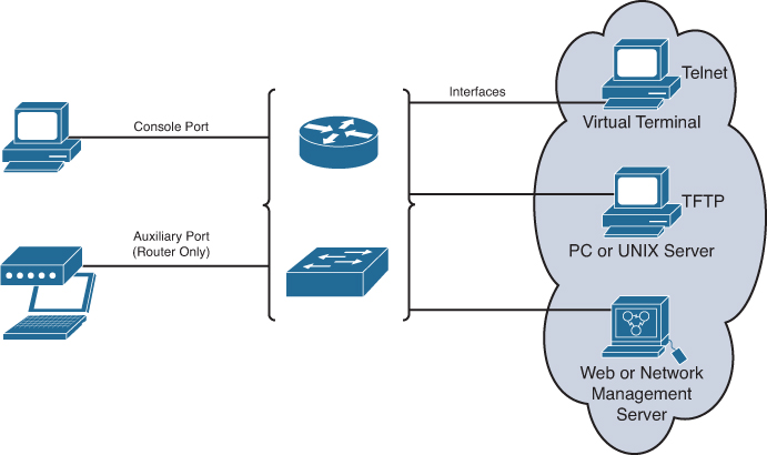
To verify and troubleshoot network operation, you use show commands. Figure 28-3 delineates the different show commands, as follows:
![]() If they are applicable to IOS (stored in RAM)
If they are applicable to IOS (stored in RAM)
![]() If they apply to the backup configuration file stored in NVRAM
If they apply to the backup configuration file stored in NVRAM
![]() If they apply to flash or specific interfaces
If they apply to flash or specific interfaces
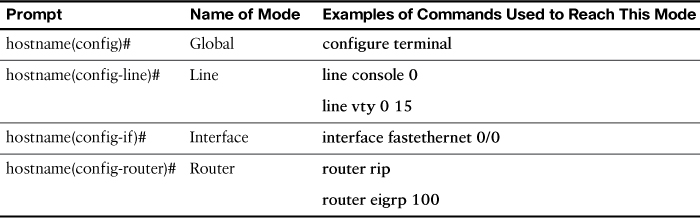
Subconfiguration Modes
To enter global configuration mode, enter the configure terminal command. From global configuration mode, IOS provides a multitude of subconfiguration modes. Table 28-4 summarizes the most common subconfiguration modes pertinent to the CCNA exam.
Storing and Erasing Configuration Files
When you configure a Cisco device, it needs to be able to retain the configuration in memory in case the switch or router loses power. Cisco devices have four main types of memory. Figure 28-4 shows these four memory types and the primary function of each.

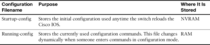
Cisco devices use two configuration files—one file used when the device is powered on and another file for the active, currently used running configuration in RAM. Table 28-5 list the names of these files, their purposes, and where they are stored in memory.
Configuration files can also be stored on a TFTP server. The configuration files can be copied between RAM, NVRAM, and a TFTP server using the copy commands, as shown in Figure 28-5.

You can use three commands to erase the contents of NVRAM. The write erase and erase startup-config commands are older, whereas the erase nvram: command is the more recent, and recommended, command. All three commands erase the contents of the NVRAM configuration file.