Day 12. DHCP Configuration
CCENT 100-101 ICND1 Exam Topics
![]() Configure and verify DHCP (IOS router).
Configure and verify DHCP (IOS router).
Key Topics
Fortunately, we normally don’t have to statically configure host devices with IP addressing. The Dynamic Host Configuration Protocol (DHCP) does the work for us. Today, we review the commands to configure a Cisco router as a DHCP server and as a DHCP client for both IPv4 and IPv6.
DHCPv4
DHCPv4 allows a host to obtain an IP address dynamically when it connects to the network. The DHCPv4 server is contacted by sending a request, and an IP address is requested. The DHCPv4 server chooses an address from a configured range of addresses called a pool and assigns it to the host client for a set period. Figure 12-1 graphically shows the process for how a DHCPv4 server fulfills a request from a DHCPv4 client.
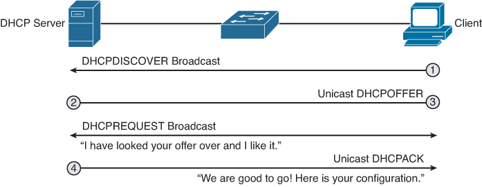
When a DHCPv4-configured device boots up or connects to the network, the client broadcasts a DHCPDISCOVER packet to identify any available DHCPv4 servers on the network. A DHCPv4 server replies with a DHCPOFFER, which is a lease offer message with an assigned IP address, subnet mask, DNS server, and default gateway information, as well as the duration of the lease.
The client can receive multiple DHCPOFFER packets if the local network has more than one DHCPv4 server. The client must choose between them and broadcast a DHCPREQUEST packet that identifies the explicit server and lease offer that it is accepting.
Assuming that the IP address is still valid, the chosen server returns a DHCPACK (acknowledgment) message finalizing the lease. If the offer is no longer valid for some reason, the chosen server responds to the client with a DHCPNAK (negative acknowledgment) message. After it is leased, the client will renew prior to the lease expiration through another DHCPREQUEST. If the client is powered down or taken off the network, the address is returned to the pool for reuse.
DHCPv4 Configuration Options
A Cisco router can be configured to handle DHCP requests in two ways: as a DHCP server and as a DHCP relay agent. A Cisco router can also be configured as a DHCP client, requesting an IPv4 address from a DHCP server for one or more of its interfaces. All of these options can be configured at the same time on the same device. For example, a router might be the DHCP server for a directly connected LAN while at the same time forwarding DHCP server requests to another DHCP server for other LANs. In addition, the router could also have one or more of its interfaces configured to request DHCP addressing from a remote server.
Configuring a Router as a DHCPv4 Server
A Cisco router running Cisco IOS Software can be configured to act as a DHCPv4 server. The Cisco IOS DHCPv4 server assigns and manages IPv4 addresses from specified address pools within the router to DHCPv4 clients.
The steps to configure a router as a DHCPv4 server are as follows:
Step 1. Use the ip dhcp excluded-address low-address [high-address] command to identify an address or range of addresses to exclude from the DHCPv4 pool. For example:
R1(config)# ip dhcp excluded-address 192.168.10.1 192.168.10.9
R1(config)# ip dhcp excluded-address 192.168.10.254
Step 2. Create the DHCPv4 pool using the ip dhcp pool pool-name command, which will then place you in DHCP config mode, as demonstrated here:
R1(config)# ip dhcp pool LAN-POOL-10
R1(dhcp-config)#
Step 3. Configure the IP addressing parameter you need to automatically assign to requesting clients. Table 12-1 lists the required commands.

Table 12-2 lists some of the more common optional DHCPv4 tasks.

Figure 12-2 shows a sample DHCPv4 topology.
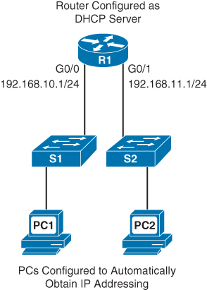
Example 12-1 shows DHCPv4 required and optional commands to configure R1 as the DHCPv4 server for both LANs.
Example 12-1 DHCPv4 Configuration Example
!Configure IP addresses that you want excluded from the DHCPv4 pool of addresses
R1(config)# ip dhcp excluded-address 192.168.10.1 192.168.10.9
R1(config)# ip dhcp excluded-address 192.168.10.254
R1(config)# ip dhcp excluded-address 192.168.11.1 192.168.11.9
R1(config)# ip dhcp excluded-address 192.168.11.254
!R1 needs two DHCPv4 pools for the two LANs. Each pool is configured with required
and optional commands.
R1(config)# ip dhcp pool LAN-POOL-10
R1(dhcp-config)# network 192.168.10.0 255.255.255.0
R1(dhcp-config)# default-router 192.168.10.1
R1(dhcp-config)# dns-server 192.168.50.195 209.165.202.158
R1(dhcp-config)# domain-name cisco.com
R1(dhcp-config)# lease 2
R1(dhcp-config)# netbios-name-server 192.168.10.254
R1(dhcp-config)# ip dhcp pool LAN-POOL-11
R1(dhcp-config)# network 192.168.11.0 255.255.255.0
R1(dhcp-config)# default-router 192.168.11.1
R1(dhcp-config)# dns-server 192.168.50.195 209.165.202.158
R1(dhcp-config)# domain-name cisco.com
R1(dhcp-config)# lease 2
R1(dhcp-config)# netbios-name-server 192.168.11.254
R1(dhcp-config)# end
Cisco IOS Software supports DHCPv4 service by default. To disable it, use the global command no service dhcp.
To verify DHCPv4 operations on the router, use the commands shown in Example 12-2.
Example 12-2 Verifying DHCPv4 Operation
R1# show ip dhcp binding
Bindings from all pools not associated with VRF:
IP address Client-ID/ Lease expiration Type
Hardware address/
User name
192.168.10.10 0100.1641.aea5.a7 Jul 18 2008 08:17 AM Automatic
192.168.11.10 0100.e018.5bdd.35 Jul 18 2008 08:17 AM Automatic
R1# show ip dhcp server statistics
Memory usage 26455
Address pools 2
Database agents 0
Automatic bindings 2
Manual bindings 0
Expired bindings 0
Malformed messages 0
Secure arp entries 0
Message Received
BOOTREQUEST 0
DHCPDISCOVER 2
DHCPREQUEST 2
DHCPDECLINE 0
DHCPRELEASE 0
DHCPINFORM 0
Message Sent
BOOTREPLY 0
DHCPOFFER 2
DHCPACK 2
DHCPNAK 0
R1#
Because PC1 and PC2 are connected to the LANs, each automatically receives its IP addressing information from the router’s DHCPv4 server. Example 12-3 shows the output from the ipconfig/all command on PC1.
Example 12-3 DHCPv4 Client Configuration
C:> ipconfig/all
Windows IP Configuration
Host Name . . . . . . . . . . . . : ciscolab
Primary Dns Suffix . . . . . . . :
Node Type . . . . . . . . . . . . : Hybrid
IP Routing Enabled. . . . . . . . : No
WINS Proxy Enabled. . . . . . . . : No
Ethernet adapter Local Area Connection:
Connection-specific DNS Suffix . : cisco.com
Description . . . . . . . . . . . : Intel(R) PRO/1000 PL
Physical Address. . . . . . . . . : 00-12-41-AE-A5-A7
Dhcp Enabled. . . . . . . . . . . : Yes
Autoconfiguration Enabled . . . . : Yes
IP Address. . . . . . . . . . . . : 192.168.10.11
Subnet Mask . . . . . . . . . . . : 255.255.255.0
Default Gateway . . . . . . . . . : 192.168.10.1
DHCP Server . . . . . . . . . . . : 192.168.10.1
DNS Servers . . . . . . . . . . . : 192.168.50.195
209.165.202.158
Primary WINS Server . . . . . . . : 192.168.10.254
Lease Obtained. . . . . . . . . . : Wednesday, July 16, 2008 8:16:59 AM
Lease Expires . . . . . . . . . . : Friday, July 18, 2008 8:16:59 AM
C:>
To release the DHCPv4 configuration on a Windows-based client, enter the ipconfig/release command. To renew the DHCPv4 configuration, enter the ipconfig/renew command.
Configuring a Router to Relay DHCPv4 Requests
In a complex network, the DHCPv4 servers are usually contained in a server farm. Therefore, clients typically are not on the same subnet as the DHCPv4 server, as shown in the previous example. To ensure that broadcasted DHCPDISCOVER messages are sent to the remote DHCPv4 server, use the ip helper-address address command.
For example, in Figure 12-3, the DHCPv4 server is located on the 192.168.11.0/24 LAN and is serving IP addressing information for both LANs.
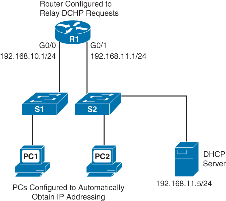
Without the ip helper-address command, R1 would discard any broadcasts from PC1 requesting DHCPv4 services. To configure R1 to relay DHCPDISCOVER messages, enter the following commands:
R1(config)# interface gigabitethernet 0/0
R1(config-if)# ip helper-address 192.168.11.5
Notice that the command is entered on the interface that will receive DHCPv4 broadcasts. R1 then forwards DHCPv4 broadcast messages as a unicast to 192.168.11.5. The ip helper-address command by default forwards the following eight UDP services:
![]() Port 37: Time
Port 37: Time
![]() Port 49: TACACS
Port 49: TACACS
![]() Port 53: DNS
Port 53: DNS
![]() Port 67: DHCP/BOOTP client
Port 67: DHCP/BOOTP client
![]() Port 68: DHCP/BOOTP server
Port 68: DHCP/BOOTP server
![]() Port 69: TFTP
Port 69: TFTP
![]() Port 137: NetBIOS name service
Port 137: NetBIOS name service
![]() Port 138: NetBIOS datagram service
Port 138: NetBIOS datagram service
To specify additional ports, use the global command ip forward-protocol udp [port-number | protocol]. To disable broadcasts of a particular protocol, use the no form of the command.
Configuring a Router as a DHCPv4 Client
Cisco routers in small offices or branch sites are often configured as DHCPv4 clients. The method used depends on the ISP. However, in its simplest configuration, the interface used to connect to a cable or DSL modem is configured with the ip address dhcp interface configuration command.
For example, in Figure 12-4, the BRANCH router’s GigabitEthernet 0/1 interface can be configured to request addressing from the ISP router.

Example 12-4 shows the configuration and verification of DHCP addressing on BRANCH.
Example 12-4 Configuring a Router as a DHCP Client
BRANCH(config)# interface g0/1
BRANCH(config-if)# ip address dhcp
BRANCH(config-if)# no shutdown
*Mar 15 08:45:34.632: %DHCP-6-ADDRESS_ASSIGN: Interface GigabitEthernet0/1 assigned
DHCP address 209.165.201.12, mask 255.255.255.224, hostname BRANCH
BRANCH(config-if)# end
BRANCH# show ip interface g0/1
GigabitEthernet0/1 is up, line protocol is up
Internet address is 209.165.201.12/27
Broadcast address is 255.255.255.255
Address determined by DHCP
<output omitted>
BRANCH#
DHCPv6
There are two methods in IPv6 to automatically obtain a global unicast address:
![]() SLAAC (Stateless Address Autoconfiguration)
SLAAC (Stateless Address Autoconfiguration)
![]() Stateful DHCPv6 (Dynamic Host Configuration Protocol for IPv6)
Stateful DHCPv6 (Dynamic Host Configuration Protocol for IPv6)
SLAAC
As we reviewed in Day 23, “IPv4 Subnetting and VLSM,” SLAAC uses ICMPv6 Router Solicitation (RS) and Router Advertisement (RA) messages to provide addressing and other configuration information. A client then uses the RA information to build an IPv6 address and verify it with a special type of Neighbor Solicitation (NS) known as Duplicate Address Detection (DAD). These three message types—RA, RS, and NS—belong to the Neighbor Discovery Protocol:
![]() Router Solicitation (RS) message: When a client is configured to obtain its addressing information automatically using SLAAC, the client will send an RS message to the router. The RS message is sent to the IPv6 all-routers multicast address, FF02::2.
Router Solicitation (RS) message: When a client is configured to obtain its addressing information automatically using SLAAC, the client will send an RS message to the router. The RS message is sent to the IPv6 all-routers multicast address, FF02::2.
![]() Router Advertisement (RA) message: A client will use this information to create its own IPv6 global unicast address. A router will send an RA message periodically or in response to an RS message. The RA message includes the prefix and prefix length of the local segment. By default, Cisco routers send RA messages every 200 seconds. RA messages are sent to the IPv6 all-nodes multicast address, FF02::1.
Router Advertisement (RA) message: A client will use this information to create its own IPv6 global unicast address. A router will send an RA message periodically or in response to an RS message. The RA message includes the prefix and prefix length of the local segment. By default, Cisco routers send RA messages every 200 seconds. RA messages are sent to the IPv6 all-nodes multicast address, FF02::1.
![]() Neighbor Solicitation (NS) message: An NS message is normally used to learn the data link layer address of a neighbor on the same network. In the SLAAC process, a host uses Duplicate Address Detection (DAD) by inserting its own IPv6 address as the destination address in an NS. The NS is sent out on the network to verify that a newly minted IPv6 address is unique. If a Neighbor Advertisement is received, the host knows that the IPv6 address is not unique.
Neighbor Solicitation (NS) message: An NS message is normally used to learn the data link layer address of a neighbor on the same network. In the SLAAC process, a host uses Duplicate Address Detection (DAD) by inserting its own IPv6 address as the destination address in an NS. The NS is sent out on the network to verify that a newly minted IPv6 address is unique. If a Neighbor Advertisement is received, the host knows that the IPv6 address is not unique.
Figure 12-5 shows the SLAAC process using three messages of the Neighbor Discovery Protocol (NDP).

Let’s briefly review the steps shown in Figure 12-5.
Step 1. PC-B sends an RS message to the all-routers multicast address, FF02::2, to inform the local IPv6 router that it needs an RA.
Step 2. RouterA receives the RS message and responds with an RA message. Included in the RA message are the prefix and prefix length of the network. The RA message is sent to the IPv6 all-nodes multicast address, FF02::1, with the link-local address of the router as the IPv6 source address.
Step 3. PC-B uses this information to create its own IPv6 global unicast address. It appends the 64-bit prefix address to its own locally generated 64-bit interface ID, which it creates either using the EUI-process (as shown in Figure 12-5) or a random number generator. It uses RouterA’s link-local address as the default gateway.
Step 4. Before PC-B can use this newly created IPv6 address, it uses the Duplicate Address Detection (DAD) process, sending out an NS to verify that the address is unique.
Note
A client’s operating system can be configured to ignore RA messages, opting always to use the services of a DHCPv6 server.
An RA message informs a client on how to obtain automatic IPv6 addressing: SLAAC, DHCPv6, or a combination of both. The RA message contains two flags to indicate the configuration option: the Managed Address Configuration flag (M flag) and the Other Configuration flag (O flag).
The default setting for these flags is 0, or both bits off. To the client, that means it is to use the SLAAC process exclusively to obtain all of its IPv6 addressing information. If for some reason, either of these flags is set to 1, you can use the no form of the following ipv6 nd commands in interface configuration mode to reset them to 0.
Router(config-if)# no ipv6 nd managed-config-flag
Router(config-if)# no ipv6 nd other-config-flag
Stateless DHCPv6
In stateless DHCPv6, the client uses the RA message from the router to generate its global unicast address. However, the client will then send a request to the DHCPv6 server to obtain any additional information not already supplied by the RA.
For stateless DHCPv6, the O flag is set to 1 so that the client is informed that additional configuration information is available from a stateless DHCPv6 server. Use the following command on the interface to modify the RA message.
Router(config-if)# ipv6 nd other-config-flag
Stateful DHCPv6
For stateful DHCPv6, the RA message informs the client to obtain all of its addressing information from a DHCPv6 server. The M flag must be set on the interface with the following command:
Router(config-if)# ipv6 nd managed-config-flag
Stateless and Stateful DHCPv6 Operation
Figure 12-6 shows the full operation of DHCPv6 regardless of the method used: SLAAC, stateless DHCPv6, or stateful DHCPv6.
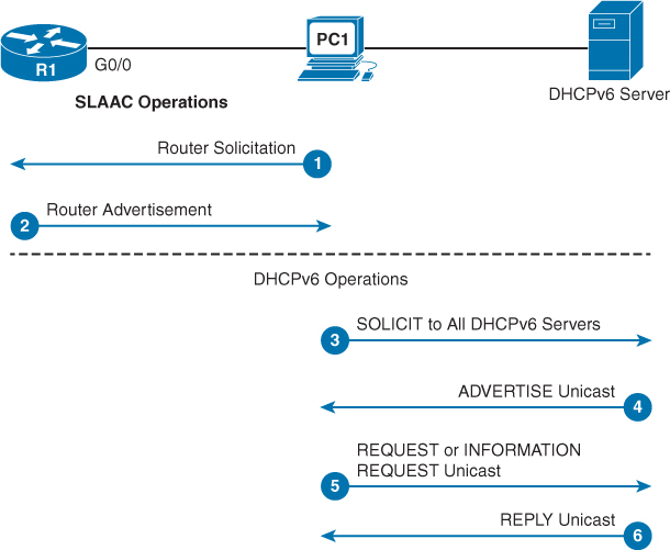
The following steps summarize Figure 12-6:
Step 1. PC1 sends an RS on bootup to begin the process of obtaining IPv6 addressing.
Step 2. R1 replies with an RA. If the M and O flags are not set, PC1 uses SLAAC. If either the M or O flag is set, PC1 begins the DHCPv6 process.
Step 3. PC1 sends a DHCPv6 SOLICIT message to the all-DHCPv6-servers address, FF02::1:2—a link-local multicast address that will not be forwarded by routers.
Step 4. A DHCPv6 server responds with a DHCPv6 ADVERTISE unicast message informing the client of its presence.
Step 5. The client then sends either a unicast DHCPv6 REQUEST (M flag was set and the client is using stateful DHCPv6) or a unicast DHCPv6 INFORMATION-REQUEST (O flag was set and the client is using stateless DHCPv6).
Step 6. The server replies with the information requested.
DHCPv6 Configuration Options
A router can be configured as a stateless DHCPv6 server, a stateful DHCPv6 server, and a DHCPv6 client. Like DHCPv4, the router can be configured with all three, depending on what role it plays for its various interfaces.
Configuring a Router as a Stateless DHCPv6 Server
We will use Figure 12-7 for all our examples in this section. R1 is the DHCPv6 server and R3 is the DHCPv6 client.
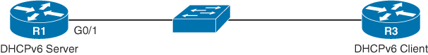
To configure R1 as a stateless DHCP server, you need to make sure that ipv6 unicast-routing is enabled. Then, in global configuration mode, configure the pool name, DNS server, and domain name. Finally, enable the DHCPv6 pool on the appropriate interface and set the O flag so that clients on that interface know to request DHCPv6 services from the router. Example 12-5 shows the configuration for R1.
Example 12-5 Configuring a Router as a Stateless DHCPv6 Server
R1(config)# ipv6 unicast-routing
R1(config)# ipv6 dhcp pool O-FLAG-SET
R1(config-dhcpv6)# dns-server 2001:db8:acad:1::5
R1(config-dhcpv6)# domain-name cisco.com
R1(config-dhcpv6)# exit
R1(config)# interface g0/1
R1(config-if)# ipv6 address 2001:db8:1:1::1/64
R1(config-if)# ipv6 dhcp server O-FLAG-SET
R1(config-if)# ipv6 nd other-config-flag
R1(config-if)# end
R1# show ipv6 dhcp pool
DHCPv6 pool: O-FLAG-SET
DNS server: 2001:DB8:ACAD:1::5
Domain name: cisco.com
Active clients: 0
R1#
To configure a router interface as a DHCPv6 client, enable IPv6 on the interface and enter the ipv6 address autoconfig command, as shown in Example 12-6. Verify the configuration with the show ipv6 interface command.
Example 12-6 Configuring an Interface as a DHCPv6 Client
R3(config)# interface g0/1
R3(config-if)# ipv6 enable
R3(config-if)# ipv6 address autoconfig
R3(config-if)# end
R3# show ipv6 interface g0/1
GigabitEthernet0/1 is up, line protocol is up
IPv6 is enabled, link-local address is FE80::32F7:DFF:FE25:2DE1
No Virtual link-local address(es):
Stateless address autoconfig enabled
Global unicast address(es):
2001:DB8:1:1:32F7:DFF:FE25:2DE1, subnet is 2001:DB8:1:1::/64 [EUI/CAL/PRE]
valid lifetime 2591935 preferred lifetime 604735
Joined group address(es):
FF02::1
FF02::1:FF25:2DE1
MTU is 1500 bytes
ICMP error messages limited to one every 100 milliseconds
ICMP redirects are enabled
ICMP unreachables are sent
ND DAD is enabled, number of DAD attempts: 1
ND reachable time is 30000 milliseconds (using 30000)
ND NS retransmit interval is 1000 milliseconds
Default router is FE80::D68C:B5FF:FECE:A0C1 on GigabitEthernet0/1
R3#
Configuring a Router as a Stateful DHCPv6 Server
The main difference between a stateless configuration and a stateful configuration is that a stateful server also includes IPv6 addressing information and keeps a record of the IPv6 addresses that are leased out. Also, for the client side, the ipv6 address dhcp command is used instead of the ipv6 address autoconfig command. Example 12-7 shows the stateful DHCPv6 server configuration with stateful address information added and the M bit set, instead of the O bit.
Example 12-7 Configuring a Router as a Stateful DHCPv6 Server
R1(config)# ipv6 unicast-routing
R1(config)# ipv6 dhcp pool M-FLAG-SET
R1(config-dhcpv6)# address prefix 2001:db8:1:1::/64 lifetime infinite infinite
R1(config-dhcpv6)# dns-server 2001:db8:acad:1::5
R1(config-dhcpv6)# domain-name cisco.com
R1(config-dhcpv6)# exit
R1(config)# interface g0/1
R1(config-if)# ipv6 address 2001:db8:1:1::1/64
R1(config-if)# ipv6 nd managed-config-flag
R1(config-if)# end
!After R3 is configured as a DHCP client, verify DHCP with the following commands:
R1# show ipv6 dhcp pool
DHCPv6 pool: M-FLAG-SET
Address allocation prefix: 2001:DB8:1:1::/64 valid 4294967295 preferred 4294967295 (1 in use, 0 conflicts)
DNS server: 2001:DB8:ACAD:1::5
Domain name: cisco.com
Active clients: 1
R1# show ipv6 dhcp binding
Client: FE80::32F7:DFF:FEA3:1640
DUID: 0003000130F70DA31640
Username : unassigned
IA NA: IA ID 0x00060001, T1 43200, T2 69120
Address: 2001:DB8:1:1:8902:60D6:E76:6C16
preferred lifetime INFINITY, , valid lifetime INFINITY,
R1#
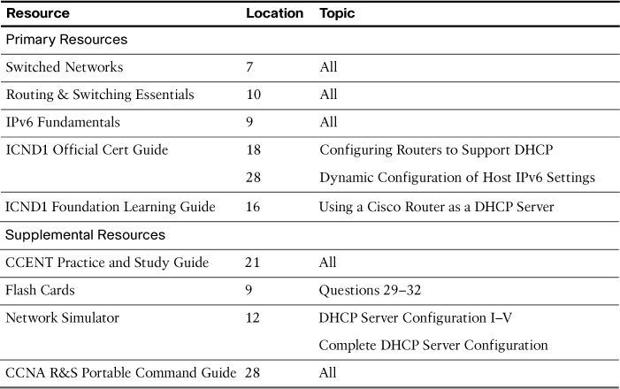
Study Resources
For today’s exam topics, refer to the following resources for more study.