Day 13. Inter-VLAN Routing Configuration
CCENT 100-101 ICND1 Exam Topics
![]() Configure and verify inter-VLAN routing (router on a stick).
Configure and verify inter-VLAN routing (router on a stick).
Key Topics
Because Layer 2 switches cannot perform the routing function, it is necessary to implement a Layer 3 device to route between VLANs. Today, we review inter-VLAN routing concepts and configurations.
Inter-VLAN Routing Concepts
Inter-VLAN communications cannot occur without a Layer 3 device. There are three options for implementing inter-VLAN routing:
![]() Traditional or legacy inter-VLAN routing
Traditional or legacy inter-VLAN routing
![]() Router on a stick
Router on a stick
![]() Multilayer switch
Multilayer switch
Let’s briefly review the concept of each method.
Legacy Inter-VLAN Routing
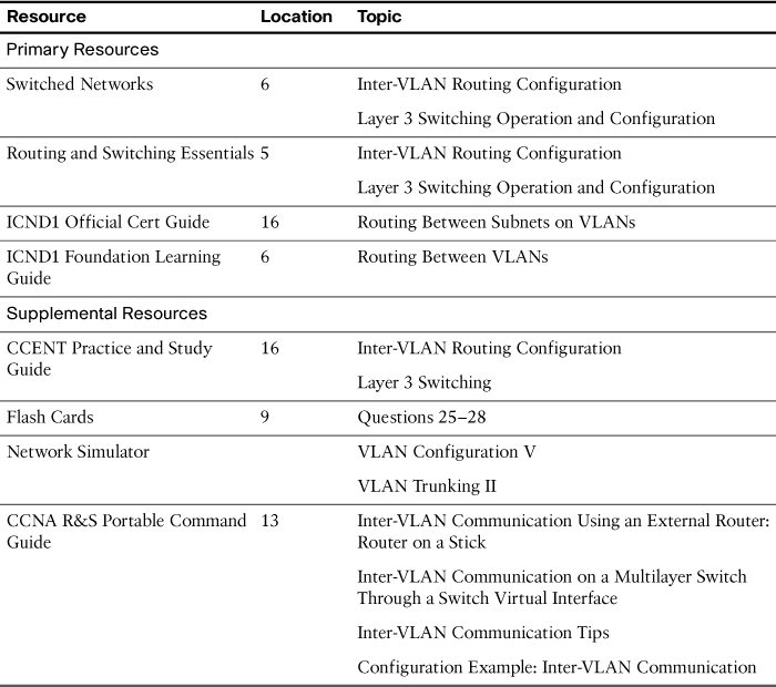
Legacy inter-VLAN routing requires multiple physical interfaces on both the router and the switch. When using a router to facilitate inter-VLAN routing, the router interfaces can be connected to separate VLANs. Devices on those VLANs send traffic through the router to reach other VLANs. For example, in Figure 13-1, each S2 interface connected to R1 is assigned to a VLAN. The router is already configured with the appropriate IP addressing on each of its interfaces, so no additional configuration is required. However, you can see that if you used a separate interface for each VLAN on a router, you would quickly run out of interfaces.
Router on a Stick
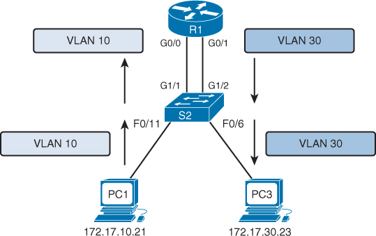
Today, router software permits configuring one router interface as multiple trunks using subinterfaces. In Figure 13-2, the physical GigabitEthernet 0/0 interface is logically subdivided into two logical interfaces. The one switch trunk is configured to trunk both VLAN 10 and VLAN 30, and each subinterface on the router is assigned a separate VLAN. The router performs inter-VLAN routing by accepting VLAN-tagged traffic on the trunk interface coming from the adjacent switch. The router then forwards the routed traffic, VLAN-tagged for the destination VLAN, out the same physical interface as it used to receive the traffic.
Multilayer Switch
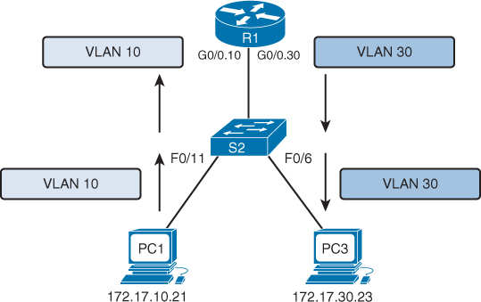
Router on a stick works fine in a small business with one or two routers. But the most scalable solution in enterprise networks today is to use a multilayer switch to replace both the router and the switch, as shown in Figure 13-3. A multilayer switch will perform both functions: switching traffic within the same VLAN and routing traffic between VLANs.

Multilayer switching is more scalable than any other inter-VLAN routing implementation because
![]() Routers have a limited number of available interfaces to connect to networks.
Routers have a limited number of available interfaces to connect to networks.
![]() Limited amounts of traffic can be accommodated on the physical link at one time.
Limited amounts of traffic can be accommodated on the physical link at one time.
With a multilayer switch, packets are forwarded down a single trunk line to obtain new VLAN-tagging information. A multilayer switch does not completely replace the functionality of a router but can be thought of as a Layer 2 device that is upgraded to have some routing capabilities.
Router on a Stick Configuration and Verification
When configuring inter-VLAN routing using the router on a stick model, the physical interface of the router must be connected to a trunk link on the adjacent switch. On the router, subinterfaces are created for each unique VLAN on the network. Each subinterface is assigned an IP address specific to its subnet/VLAN and is also configured to tag frames for that VLAN. This way, the router can keep the traffic from each subinterface separated as it traverses the trunk link back to the switch.
Configuring inter-VLAN routing is pretty straightforward. Refer to the sample topology shown in Figure 13-4 to review the commands.

This router on a stick topology is configured using the following steps on the router:
Step 1. Activate the physical interface that is trunking with the switch using the no shutdown command.
Step 2. Enter subinterface configuration mode for the first VLAN that needs routing. One convention is to use the VLAN number as the subinterface number. For example, the interface g0/1.10 command enters subinterface configuration mode for VLAN 10.
Step 3. Configure the trunking encapsulation type using the subinterface configuration command encapsulation {dot1q | isl} vlan-number [native]. Set the encapsulation to dot1q.
![]() Inter-switch link (ISL) encapsulation—a Cisco-proprietary trunking method—existed prior to the IEEE 802.1Q standard, which is now the recommended best practice. However, older switches that are still in use might only support ISL. In those cases, you would substitute the dot1q keyword for isl.
Inter-switch link (ISL) encapsulation—a Cisco-proprietary trunking method—existed prior to the IEEE 802.1Q standard, which is now the recommended best practice. However, older switches that are still in use might only support ISL. In those cases, you would substitute the dot1q keyword for isl.
![]() On some routers, the optional keyword native must be configured for the native VLAN before the router will route native VLAN traffic. Native VLAN routing is not shown in the following examples. Refer to your Study Resources for more on the native VLAN.
On some routers, the optional keyword native must be configured for the native VLAN before the router will route native VLAN traffic. Native VLAN routing is not shown in the following examples. Refer to your Study Resources for more on the native VLAN.
Step 4. Configure the IP address and subnet mask.
Step 5. Repeat Steps 2–4 for each additional VLAN that needs routing.
Assuming that the switch is already configured with VLANs and trunking, Example 13-1 shows the commands to configure R1 to provide routing between VLAN 10 and VLAN 30.
Example 13-1 Configuring R1 to Route Between VLANs
R1(config)# interface g0/0
R1(config-if)# no shutdown
R1(config-if)# interface g0/1.10
R1(config-subif)# encapsulation dot1q 10
R1(config-subif)# ip add 172.17.10.1 255.255.255.0
R1(config-subif)# interface g0/1.30
R1(config-subif)# encapsulation dot1q 30
R1(config-subif)# ip add 172.17.30.1 255.255.255.0
To verify the configuration, use the show vlans, show ip route, and show ip interface brief commands to make sure that the new networks are in the routing table and that the subinterfaces are “up” and “up,” as shown in Example 13-2.
Example 13-2 Verifying the Inter-VLAN Routing Configuration
R1# show vlans
<output omitted>
Virtual LAN ID: 10 (IEEE 802.1Q Encapsulation)
vLAN Trunk Interface: GigabitEthernet0/0.10
Protocols Configured: Address: Received: Transmitted:
IP 172.17.10.1 0 0
<output omitted>
Virtual LAN ID: 30 (IEEE 802.1Q Encapsulation)
vLAN Trunk Interface: GigabitEthernet0/0.30
Protocols Configured: Address: Received: Transmitted:
IP 172.17.30.1 0 0
<output omitted>
R1# show ip route
<output omitted>
Gateway of last resort is not set
172.17.0.0/16 is variably subnetted, 4 subnets, 2 masks
C 172.17.10.0/24 is directly connected, GigabitEthernet0/0.10
L 172.17.10.1/32 is directly connected, GigabitEthernet0/0.10
C 172.17.30.0/24 is directly connected, GigabitEthernet0/0.30
L 172.17.30.1/32 is directly connected, GigabitEthernet0/0.30
R1# show ip interface brief
Interface IP-Address OK? Method Status Protocol
GigabitEthernet0/0 unassigned YES unset up up
GigabitEthernet0/0.10 172.17.10.1 YES manual up up
GigabitEthernet0/0.30 172.17.30.1 YES manual up up
GigabitEthernet0/1 unassigned YES unset administratively down down
Serial0/0/0 unassigned YES manual administratively down down
Serial0/0/1 unassigned YES manual administratively down down
Vlan1 unassigned YES manual administratively down down
R1#
Assuming that the switch and PCs are configured correctly, the two PCs should now be able to ping each other. R1 will route the traffic between VLAN 10 and VLAN 30.
Multilayer Switch Inter-VLAN Routing Configuration and Verification
Most enterprise networks use multilayer switches to achieve high-packet processing rates using hardware-based switching. All Catalyst multilayer switches support the following types of Layer 3 interfaces:
![]() Routed port: Similar to a physical interface on a Cisco IOS router
Routed port: Similar to a physical interface on a Cisco IOS router
![]() Switch virtual interface (SVI): Virtual VLAN interface used for inter-VLAN routing
Switch virtual interface (SVI): Virtual VLAN interface used for inter-VLAN routing
All Layer 3 Cisco Catalyst switches support routing protocols (3500, 4500, and 6500 series). Catalyst 2960 Series switches running IOS Release 12.2(55) or later support static routing.
Creating Additional SVIs
The SVI for the default VLAN (VLAN1) already exists to permit remote switch administration. For a topology like the one shown in Figure 13-5, additional SVIs must be explicitly created.
Create an SVI using the interface vlan vlan-id command. The vlan-id used corresponds to the VLAN tag associated with data frames coming from that VLAN. For example, when creating an SVI as a gateway for VLAN 10, use the interface VLAN 10 command. Assign an IP address and enable the new SVI with the no shutdown command.
The following are some of the advantages of SVIs (the only disadvantage is that multilayer switches are more expensive):
![]() They are much faster than routers on a stick because everything is hardware switched and routed.
They are much faster than routers on a stick because everything is hardware switched and routed.
![]() There is no need for external links from the switch to the router for routing.
There is no need for external links from the switch to the router for routing.
![]() They are not limited to one link. Layer 2 EtherChannels can be used between the switches to get more bandwidth.
They are not limited to one link. Layer 2 EtherChannels can be used between the switches to get more bandwidth.
![]() Latency is much lower because it does not need to leave the switch.
Latency is much lower because it does not need to leave the switch.
Configuring a 2960 to Route Between VLANs
The Catalyst 2960 switch shown in Figure 13-6 can function as a Layer 3 device and route between VLANs by enabling the Cisco Switch Database Manager (SDM) template for LAN-based routing.

The following steps show how to configure a 2960 to do Layer 3 switching. The rest of the steps after Step 1 would apply to all models of Cisco switches that are capable of doing Layer 3 switching.
Step 1. With IOS Release 12.2(55) or later, enable hardware support for IPv4 routing with the sdm prefer lanbase-routing global command and reload the switch, as shown in Example 13-3.
Example 13-3 Enable Hardware Support for IPv4 Routing
S2(config)# sdm prefer lanbase-routing
Changes to the running SDM preferences have been stored, but cannot take effect
until the next reload.
Use 'show sdm prefer' to see what SDM preference is currently active.
Switch(config)# do reload
System configuration has been modified. Save? [yes/no]: yes
Building configuration...
[OK]
Proceed with reload? [confirm]
S2# show sdm prefer
The current template is "lanbase-routing" template.
<output omitted>
Step 2. Create VLAN interfaces for each VLAN for which the Layer 3 switch is routing packets (interface vlan vlan_id), as shown in Example 13-3.
Step 3. Configure an IP address and mask on the VLAN interface.
Step 4. If the switch defaults to place the VLAN interface in a disabled (shutdown) state, enable the interface (no shutdown). Steps 2–4 are shown in Example 13-4.
Example 13-4 Create and Assign Addressing to SVIs
S2(config-if)# interface vlan 30
S2(config-if)# ip address 172.17.30.1 255.255.255.0
S2(config-if)# no shutdown
Mar 20 01:00:25.021: %LINEPROTO-5-UPDOWN: Line protocol on Interface Vlan30,
changed state to up
S2(config-if)# interface vlan 10
S2(config-if)# ip address 172.17.10.1 255.255.255.0
S2(config-if)# no shutdown
Mar 20 01:00:25.021: %LINEPROTO-5-UPDOWN: Line protocol on Interface Vlan10,
changed state to up
S2(config-if)#
Step 5. Enable IPv4 routing globally (ip routing), verify that the switch now has a routing table, and test connectivity between PCs in different VLANS, as shown in Example 13-5.
Example 13-5 Enable Routing and Verify Connectivity
S2(config-if)# do show ip route
<output omitted>
Gateway of last resort is not set
172.17.0.0/16 is variably subnetted, 4 subnets, 2 masks
C 172.17.10.0/24 is directly connected, Vlan10
L 172.17.10.1/32 is directly connected, Vlan10
C 172.17.30.0/24 is directly connected, Vlan30
L 172.17.30.1/32 is directly connected, Vlan30
S2(config)#
!Ping PC1 from PC3
C:> ping 172.17.10.21
Pinging 172.17.10.21 with 32 bytes of data:
Reply from 172.17.10.21: bytes=32 time=5ms TTL=127
Reply from 172.17.10.21: bytes=32 time=1ms TTL=127
Reply from 172.17.10.21: bytes=32 time=<1ms TTL=127
Reply from 172.17.10.21: bytes=32 time=<1ms TTL=127
Ping statistics for 172.17.10.21:
Packets: Sent = 4, Received = 4, Lost = 0 (0% loss),
Approximate round trip times in milli-seconds:
Minimum = 19ms, Maximum = 5ms, Average = 19ms
C:>
Note
The CCENT exam topics about inter-VLAN routing mention “upstream routing,” which simply means that even if a router or switch can route between VLANs, it will still need to be able to route most traffic “upstream” to other areas of the enterprise and to the Internet.