Day 24. The IPv4 Address
CCENT 100-101 ICND1 Exam Topics
![]() Describe the operation and necessity of using private and public IP addresses for IPv4 addressing.
Describe the operation and necessity of using private and public IP addresses for IPv4 addressing.
Key Topics
Today, we focus on reviewing the structure of an IPv4 address, the classes, as well as private and public IPv4 addresses. Tomorrow, we will review IPv4 subnetting.
IPv4 Addressing
Although IPv6 is rapidly permeating the networks of the world, most networks still have a large IPv4 implementation. Especially on private networks, migration away from IPv4 will take years to complete. So IPv4 and your skill in its use are still in demand.
Header Format
To facilitate the routing of packets over a network, the TCP/IP protocol suite uses a 32-bit logical address known as an IP address. This address must be unique for each device in the internetwork.
Figure 24-1 shows the layout of the IPv4 header.
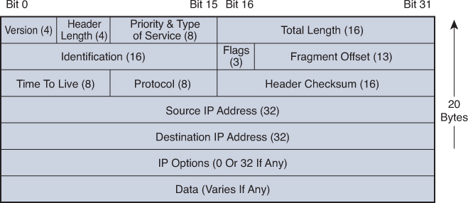
Note that each IP packet carries this header, which includes a source IP address and destination IP address.
An IP address consists of two parts:
![]() The high-order, or leftmost, bits specify the network address component (network ID) of the address.
The high-order, or leftmost, bits specify the network address component (network ID) of the address.
![]() The low-order, or rightmost, bits specify the host address component (host ID) of the address.
The low-order, or rightmost, bits specify the host address component (host ID) of the address.
Classes of Addresses
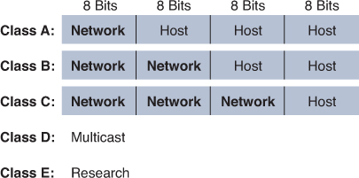
From the beginning, IPv4 was designed with class structure: Classes A, B, C, D, and E. Class D is used for multicasting addresses and Class E is reserved for experimentation. Classes A, B, and C are assigned to network hosts. To provide a hierarchical structure, these classes are divided into network and host portions, as shown in Figure 24-2. The high-order bits specify the network ID, and the low-order bits specify the host ID.
In a classful addressing scheme, devices that operate at Layer 3 can determine the address class of an IP address from the format of the first few bits in the first octet. Initially, this was important so that a networking device could apply the default subnet mask for the address and determine the host address. Table 24-1 summarizes how addresses are divided into classes, the default subnet mask, the number of networks per class, and the number of hosts per classful network address.
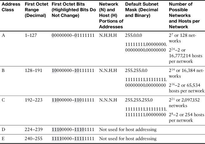
In the last column, the “minus 2” for hosts per network is to account for the reserved network and broadcast addresses for each network. These two addresses cannot be assigned to hosts.
Note
We are not reviewing the process of converting between binary and decimal. At this point in your studies, you should be very comfortable moving between the two numbering systems. If not, take some time to practice this necessary skill. You can search the Internet for binary conversion tricks, tips, and games to help you practice.
Purpose of the Subnet Mask
Subnet masks are always a series of 1 bits followed by a series of 0 bits. The boundary where the series changes from 1s to 0s is the boundary between the network and host. This is how a device that operates at Layer 3 determines the network address for a packet—by finding the bit boundary where the series of 1 bits ends and the series of 0 bits begins. The bit boundary for default subnet masks breaks on the octet boundary. Determining the network address for an IP address that uses a default mask is easy.
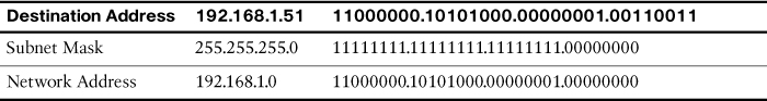
For example, a router receives a packet destined for 192.168.1.51. By “ANDing” the IP address and the subnet mask, the router determines the network address for the packet. By the ANDing rules, a 1 AND a 1 equals 1. All other possibilities equal 0. Table 24-2 shows the results of the ANDing operation. Notice that the host bits in the last octet are ignored.
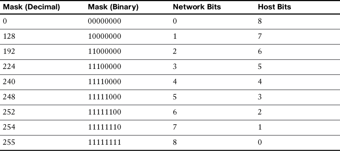
The bit boundary can now occur in just about any place in the 32 bits. Table 24-3 summarizes the values for the last nonzero octet in a subnet mask.
Private and Public IP Addressing
RFC 1918, “Address Allocation for Private Internets,” eased the demand for IP addresses by reserving the following addresses for use in private internetworks:
![]() Class A: 10.0.0.0/8 (10.0.0.0–10.255.255.255)
Class A: 10.0.0.0/8 (10.0.0.0–10.255.255.255)
![]() Class B: 172.16.0.0/12 (172.16.0.0–172.31.255.255)
Class B: 172.16.0.0/12 (172.16.0.0–172.31.255.255)
![]() Class C: 192.168.0.0/16 (192.168.0.0–192.168.255.255)
Class C: 192.168.0.0/16 (192.168.0.0–192.168.255.255)
If you are addressing a nonpublic intranet, these private addresses are normally used instead of globally unique public addresses. This provides flexibility in your addressing design. Any organization can take full advantage of an entire Class A address (10.0.0.0/8). Forwarding traffic to the public Internet requires translation to a public address using Network Address Translation (NAT). But by overloading an Internet-routable address with many private addresses, a company needs only a handful of public addresses. Day 9 reviews NAT operation and configuration in greater detail.
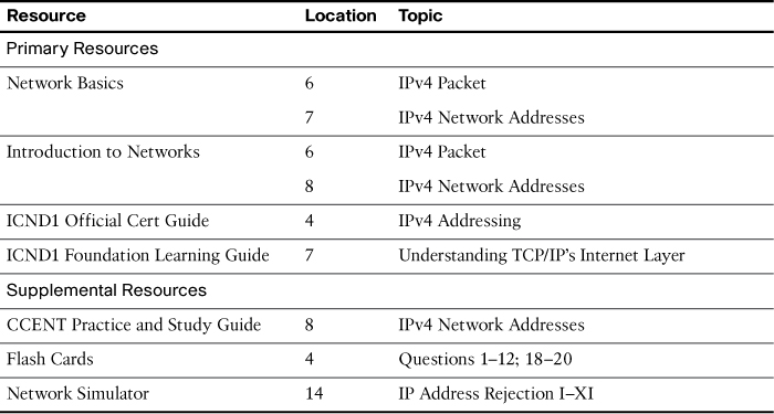
Study Resources
For today’s exam topics, refer to the following resources for more study.