Day 17. Basic Router Configuration: IPv6
CCENT 100-101 ICND1 Exam Topics
![]() Configure and verify utilizing the CLI to set basic router configuration.
Configure and verify utilizing the CLI to set basic router configuration.
![]() Configure and verify operation status of an Ethernet interface.
Configure and verify operation status of an Ethernet interface.
![]() Verify router configuration and network connectivity.
Verify router configuration and network connectivity.
Key Topic
Today we review addressing a router with IPv6 and testing network connectivity for both IPv4 and IPv6.
Basic Router Configuration with IPv6
In this section, we will use the topology shown in Figure 17-1 to review the basic commands for enabling IPv6 on a router.

First, you must enable IPv6 routing using the following command in global configuration mode:
R1(config)# ipv6 unicast-routing
This command will, among other things, configure the router to begin listening for and responding to Neighbor Discovery (ND) messages on all active IPv6 interfaces.
To configure an IPv6 address on a router’s interface, you have one of several options:
![]() Configure the interface to use the EUI-64 method of addressing.
Configure the interface to use the EUI-64 method of addressing.
Router(config)# ipv6 address ipv6-prefix/prefix-length eui-64
![]() Configure the full global unicast address. To manually configure a full IPv6 address, use the following command syntax:
Configure the full global unicast address. To manually configure a full IPv6 address, use the following command syntax:
Router(config)# ipv6 address ipv6-address/prefix-length
![]() Configure the interface as unnumbered (see Day 22, “IPv6 Addressing Concepts”).
Configure the interface as unnumbered (see Day 22, “IPv6 Addressing Concepts”).
![]() Configure the interface as a DHCPv6 client (see Day 12, “DHCP Configuration”)
Configure the interface as a DHCPv6 client (see Day 12, “DHCP Configuration”)
Note
To manually configure an interface’s link-local address, use the following command syntax:
Router(config)# ipv6 address ipv6-address/prefix-length link-local
Often, the preferred method is to manually configure the full IPv6 address because you can control the number of hexadecimal digits you must type when testing connectivity or troubleshooting a problem. We can see this by comparing the EUI-64 method to a full configuration. In Example 17-1, the interfaces on R1 are all configured using the EUI-64 method.
Example 17-1 Configuring Interfaces Using the EUI-64 Method
R1(config)# interface g0/0
R1(config-if)# ipv6 address 2001:db8:acad:1::/64 eui-64
R1(config-if)# interface g0/1
R1(config-if)# ipv6 address 2001:db8:acad:2::/64 eui-64
R1(config-if)# interface s0/0/0
R1(config-if)# ipv6 address 2001:db8:acad:3::/64 eui-64
R1(config-if)# do show ipv6 interface brief
GigabitEthernet0/0 [up/up]
FE80::2D0:97FF:FE20:A101
2001:DB8:ACAD:1:2D0:97FF:FE20:A101
GigabitEthernet0/1 [up/up]
FE80::2D0:97FF:FE20:A102
2001:DB8:ACAD:2:2D0:97FF:FE20:A102
Serial0/0/0 [down/down]
FE80::20C:CFFF:FE77:A401
2001:DB8:ACAD:3:20C:CFFF:FE77:A401
<output omitted>
Notice the number of hexadecimal digits in the IPv6 addresses highlighted in the output from the show ipv6 interface brief command. Imagine having to ping the GigabitEthernet 0/0 address 2001:DB8:ACAD:1:2D0:97FF:FE20:A101.
Furthermore, notice that the link-local addresses are also rather complex. To reduce the complexity of the router’s configuration, verification, and troubleshooting, it is a good practice to manually configure the link-local address as well as the IPv6 global unicast address. In Example 17-2, R1 is reconfigured with simpler IPv6 addresses and with FE80::1 as the link-local address on all interfaces. Remember, the link-local address only needs to be unique on that interface’s link.
Example 17-2 Full IPv6 Address and Link-Local Address Configuration
R1(config-if)# interface g0/0
R1(config-if)# no ipv6 address 2001:db8:acad:1::/64 eui-64
R1(config-if)# ipv6 address 2001:db8:acad:1::1/64
R1(config-if)# ipv6 address fe80::1 link-local
R1(config-if)# interface g0/1
R1(config-if)# no ipv6 address 2001:db8:acad:2::/64 eui-64
R1(config-if)# ipv6 address 2001:db8:acad:2::1/64
R1(config-if)# ipv6 address fe80::1 link-local
R1(config-if)# interface s0/0/0
R1(config-if)# no ipv6 address 2001:db8:acad:3::/64 eui-64
R1(config-if)# ipv6 address 2001:db8:acad:3::1/64
R1(config-if)# ipv6 address fe80::1 link-local
R1(config-if)# do show ipv6 interface brief
GigabitEthernet0/0 [up/up]
FE80::1
2001:DB8:ACAD:1::1
GigabitEthernet0/1 [up/up]
FE80::1
2001:DB8:ACAD:2::1
Serial0/0/0 [down/down]
FE80::1
2001:DB8:ACAD:3::1
<output omitted>
Note
If you do not remove the previous IPv6 address configuration, each interface will have two IPv6 global unicast addresses. This is different than IPv4, where simply configuring another IPv4 address with the ip address command overwrites any previous configuration. However, there can only be one link-local address per interface.
Compare the highlighted output from the show ipv6 interface brief command in Example 17-2 with the output in Example 17-1. You can see that simplifying the IPv6 addressing implementation can make your verification and troubleshooting job much easier.
To verify the full configuration of an interface, use the show ipv6 interface command. Example 17-3 shows the output for R1’s GigabitEthernet 0/0 interface.
Example 17-3 show ipv6 interface gigabitethernet 0/0 Command
R1# show ipv6 interface gigabitethernet 0/0
GigabitEthernet0/0 is up, line protocol is up
IPv6 is enabled, link-local address is FE80::1
No Virtual link-local address(es):
Global unicast address(es):
2001:DB8:ACAD:1::1, subnet is 2001:DB8:ACAD:1::/64
Joined group address(es):
FF02::1
FF02::1:FF00:1
MTU is 1500 bytes
ICMP error messages limited to one every 100 milliseconds
ICMP redirects are enabled
ICMP unreachables are sent
ND DAD is enabled, number of DAD attempts: 1
ND reachable time is 30000 milliseconds
ND advertised reachable time is 0 milliseconds
ND advertised retransmit interval is 0 milliseconds
ND router advertisements are sent every 200 seconds
ND router advertisements live for 1800 seconds
ND advertised default router preference is Medium
Hosts use stateless autoconfig for addresses.
Focus on the highlighted output. IPv6 is enabled on this interface with a nice, short link-local address. The global unicast address and its subnet are listed as well as the address of multicast groups that this interface automatically joined. Do you remember what the FF02::1 and FF02::1:FF00:1 addresses are used for? If not, revisit Day 22, “IPv6 Addressing Concepts.”
That’s all the IPv6 configurations for today. As we continue to review the exam topics in the upcoming days, we will incorporate IPv6 topics.
Verifying IPv4 and IPv6 Network Connectivity
As reviewed on Day 27, “Basic Switch Configuration,” ping and traceroute are helpful tools for verifying network connectivity. Example 17-4 demonstrates successful ping output on the router.
Example 17-4 Ping Output on a Router
R1# ping 192.168.3.10
Type escape sequence to abort.
Sending 5, 100-byte ICMP Echos to 192.168.3.10, timeout is 2 seconds:
!!!!!
Success rate is 100 percent (5/5), round-trip min/avg/max = 1/2/4 ms
!Pinging an IPv6 destination
R1# ping 2001:db8:acad:1:290:dff:fee5:8095
Type escape sequence to abort.
Sending 5, 100-byte ICMP Echos to 2001:DB8:ACAD:1:290:CFF:FEE5:8095, timeout is 2
seconds:
!!!!!
Success rate is 100 percent (5/5), round-trip min/avg/max = 0/9/46 ms
R1#
Unsuccessful ping output shows periods (.) instead of exclamation points (!), as demonstrated in Example 17-5. The output would be the same for IPv6.
Example 17-5 Unsuccessful Ping Output on a Router
R1# ping 192.168.3.2
Type escape sequence to abort.
Sending 5, 100-byte ICMP Echos to 192.168.3.2, timeout is 2 seconds:
.....
Success rate is 0 percent (0/5)
R1#
Example 17-6 shows output from a successful traceroute command.
Example 17-6 traceroute Output on a Router
R1# traceroute 192.168.3.10
Type escape sequence to abort.
Tracing the route to 192.168.3.10
1 192.168.2.2 71 msec 70 msec 72 msec
2 192.168.3.10 111 msec 133 msec 115 msec
R1#
!Tracing to an IPv6 destination.
R2# traceroute 2001:db8:acad:1:290:cff:fee5:8095
Type escape sequence to abort.
Tracing the route to 2001:DB8:ACAD:1:290:CFF:FEE5:8095
1 2001:DB8:ACAD:3::11 msec 1 msec 1 msec
2 2001:DB8:ACAD:1:290:CFF:FEE5:80951 msec 1 msec 0 msec
R2#
Unsuccessful traces will show the last successful hop and the asterisks for each attempt until the user cancels. To cancel the traceroute command on a router, press the key combination Ctrl-Shift-6 and then the x key. Example 17-7 shows unsuccessful traceroute output. The output would be the same for IPv6.
Example 17-7 Unsuccessful traceroute Output on a Router
R1# traceroute 192.168.3.2
Type escape sequence to abort.
Tracing the route to 192.168.3.2
1 192.168.2.2 71 msec 70 msec 72 msec
2 * * *
3 * * *
4 * * *
5 *
R1#
Using Telnet or SSH to remotely access another device also tests connectivity. More importantly, these remote access methods will test whether a device has been correctly configured so that you can access it for management purposes. This can be very important when a device is truly remote (for example, across town or in another city). Day 27 reviews SSH configuration and verification in greater detail.
During our basic configuration tasks earlier, we entered the commands to properly configure the vty lines for SSH remote access. If accessing a device configured with SSH from a PC, you use the SSH setting in your terminal client. However, you can use the ssh command on a router or switch to access another device configured with SSH. Example 17-8 shows how to use SSH to remotely access R2 from R1.
Example 17-8 Remote Access Using SSH
R1# ssh ?
-c Select encryption algorithm
-l Log in using this user name
-m Select HMAC algorithm
-o Specify options
-p Connect to this port
-v Specify SSH Protocol Version
-vrf Specify vrf name
WORD IP address or hostname of a remote system
R1# ssh -l ?
WORD Login name
R1# ssh -l admin ?
-c Select encryption algorithm
-m Select HMAC algorithm
-o Specify options
-p Connect to this port
-v Specify SSH Protocol Version
-vrf Specify vrf name
WORD IP address or hostname of a remote system
R1# ssh -l admin 192.168.2.2
Password:
******************************************
WARNING!! Unauthorized Access Prohibited!!
******************************************
R2>
Note
During your CCENT studies and lab practice, you more than likely used a Telnet configuration to remotely access your lab equipment. Although Telnet is easier to use than SSH, remember that SSH is considered best practice. Therefore during the CCENT exam, be ready to use SSH to remotely access devices on simulation questions as Telnet might not be configured or allowed.
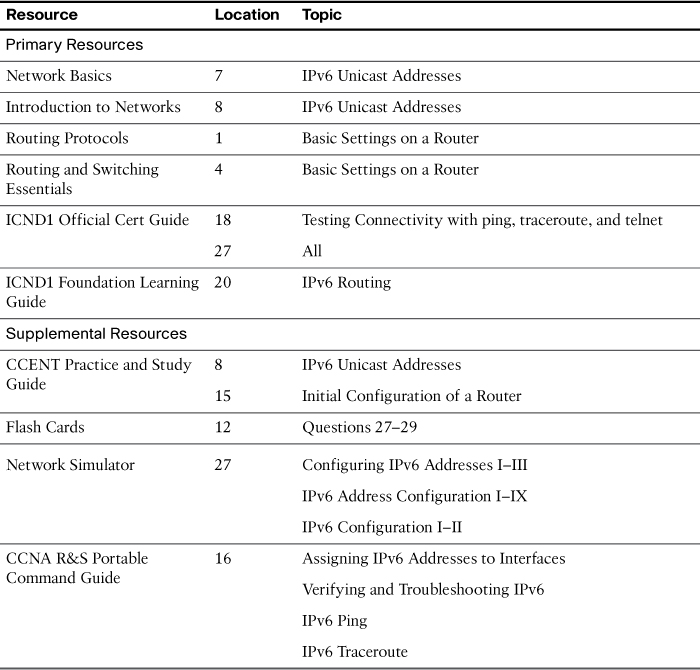
Study Resources
For today’s exam topics, refer to the following resources for more study.