
AutoCAD and AutoCAD LT have been around for a long time. As a result, the way you give the program commands — called the user interface — is somewhat unique. You can give the same command in several ways. In this chapter, you read about the various possibilities and start to get acquainted with all of them.
Note
In AutoCAD 2010 and AutoCAD LT 2010, the emphasis is to provide one place only (with exceptions) to give a command when you use the new interface, but the older interface methods still exist.
Commands are important. In a word processing program, you can simply start typing, and in a spreadsheet program, you can begin by entering data; but in most cases nothing happens in AutoCAD or AutoCAD LT until you give it a command.
Many new commands have been added to AutoCAD and AutoCAD LT over the years. Often, older commands that were no longer necessary were kept to maintain compatibility with earlier releases. A number of these older commands, as well as certain rarely used commands, are not found in the interface. Other than this idiosyncrasy, the interface is similar to those of other Windows programs. Specifically, the ribbon is similar to the latest version of Microsoft Office.
You use the user interface to execute commands and to specify settings and values. The user interface consists of the default ribbon, drop-down menus, shortcut (right-click, or contextual) menus, toolbars, palettes, the dynamic input tooltip, dialog boxes, and the command line. For executing commands, all the aspects of the user interface except dialog boxes work in conjunction with the command line. Looking at the command line whenever you execute a command is important, because that command appears on the command line, and a prompt or list of options may appear as well. If you have Dynamic Input on, the tooltip also displays the prompt. (Click the Dynamic Input button on the status bar to turn it on — and off.) See the section, "Responding to commands," later in this chapter for more information on what to do next.
AutoCAD 2010 and AutoCAD LT 2010 use a ribbon, which is a horizontal, tabbed area at the top of the screen. The ribbon contains buttons like a toolbar, but is wider. You can drag it to the left or right side of your screen to make it vertical. You can customize the ribbon, as I explain in Chapter 33. The ribbon is the user interface in the default workspace, 2D Drafting & Annotation. It's also the user interface for the 3D Modeling workspace that comes with AutoCAD (but not with AutoCAD LT). You can return to the earlier user interface by switching to the AutoCAD Classic or AutoCAD LT Classic workspace. Click the Workspace Switching button on the right side of the status bar, and choose AutoCAD Classic or AutoCAD LT Classic from the pop-up menu.
The Home tab contains many of the commands that you use most often. The ribbon is divided into control panels (panels, for short). Each panel contains a related group of commands. Many of the panels have a down arrow to the right of the panel name that you can click to display more buttons for commands that you don't use as often.
Note
Some panels have an arrow at the right end of the panel title, which opens a related dialog box. This arrow is called a dialog box launcher. Also, when you select certain types of objects, contextual tabs appear. For example, if you insert an image into a drawing and select the image, the Image tab appears.
This book provides instructions for executing a command by using the default workspace. To find the location of a command in the Classic workspace, look up the command name (which I usually provide) in Help's Command Reference. I explain how to use the Help system at the end of this chapter.
To execute a command, click the tab that you need, and click the command's button. If the button doesn't have a label, hover the mouse cursor over it to read its tooltip and a brief description of the button's command. If you continue to hover a little longer, the description expands, explaining the command in more detail. Some items on the ribbon are drop-down lists from which you choose an option.
Note
The ribbon and Quick Access toolbar support a new feature called keytips. Keytips allow you to access commands and controls with a keyboard combination. To display keytips, press the Alt key. Keytips are not available when you display the menu bar. The menu bar is covered in the following section.
Full ribbon. Displays the current tab and all its buttons
Tabs. Displays one row of the tab names only
Panel titles. Displays the tab names and the panel names for the current tab
To move the ribbon to the left or right of your screen in a vertical configuration, right-click any blank space on the tab bar at the top of the ribbon, and choose Undock. The ribbon undocks and then functions like a palette, which I cover later in this chapter. You can dock it on the left or right and auto-hide it. Right-click the gray, vertical title bar for more options.
The Application menu is under the Application Button at the upper-left corner of the screen. The menu contains file-related commands, such as saving, exporting, and printing.
Note
In AutoCAD 2010 and AutoCAD LT 2010, the Application menu takes the place of the Menu Browser that was in the previous release. It does not contain the entire menu; instead, it offers only file-related options. However, you can display the drop-down menu at the top of the screen as described in the next section, "Using menus." At the top of the Application menu, you can use the Search box to search for a command. The results show you where to find that command.
Note
In early releases, AutoCAD provided a menu on the right side of the screen, called the screen menu. Few people still use it these days. AutoCAD's current default is to not show the screen menu, so I don't cover it in this book. If you must have the screen menu, you can easily display it. Choose Application Button
Shortcut menus appear when you right-click your mouse. The purpose of shortcut menus is to speed up your work; they can be faster than using the command line because you don't have to take your eyes off the screen. The shortcut menus try to anticipate the most common tasks you might want to complete. As a result, the menu that appears when you right-click depends on the situation:
If you have neither started a command nor selected any objects, you get the default menu when you right-click in the drawing area. Here you can cut, copy, paste, undo, pan, zoom, and so on.
If you've selected any objects, you see the edit-mode menu, which lists the most common editing commands.
If you've started a command, the command-mode menu opens, letting you choose an option for that command. I explain this in more detail later in this chapter.
When a dialog box is open, you can right-click active sections to see the dialog-mode menu, which varies with the dialog box.
Other menus include the toolbar list you get when you right-click a toolbar and the command-line history you see when you right-click the command line and choose Recent Commands.
In early releases, right-clicking was equivalent to pressing Enter. You can customize how right-clicking works — and that includes changing it back to the way it worked in earlier releases. Choose Application Button
Tip
When you set right-click customization, you can turn on time-sensitive right-clicking. Time-sensitive right-clicking is a great feature that gives you the best of two worlds — the right mouse button can be used both as an equivalent to pressing Enter and as a way to open the shortcut menus. If you turn on time-sensitive right-clicking, a quick right-click is equivalent to pressing Enter and will repeat the last command or end any commands that require Enter to end. A longer right-click (hold your finger on the mouse button slightly longer) opens the shortcut menu. You can specify the length of time required for the longer right-click, which is 250 milliseconds by default.
Dialog boxes offer the user a simple way to control AutoCAD or AutoCAD LT without memorizing a lot of technical commands and option names. They guide you through a task by clearly laying out all the choices. If you're familiar with any other Windows program, you're familiar with dialog boxes. Dialog boxes provide contextual help in the form of a tooltip that provides information on an option or control. To use contextual tooltips, position the cursor over a control.
Tip
You can enter mathematical expressions for values in dialog box text boxes; start an expression with an equal sign (=). For example, in the Angle box of the Hatch and Gradient (Hatch if you are using AutoCAD LT) dialog box, you can enter =20+10. Press Alt+Enter to complete the process. You can also enter mathematical expressions in palette text boxes.
When you've finished using a dialog box, click OK to accept any settings you specified, or click Cancel to discard any changes. In some cases, you can click Apply to save the changes made without closing the dialog box.
Toolbars provide a quick way to execute a command with one click of the mouse. If you're not sure what a toolbar button does, hover the cursor over a button and read the tooltip.
Note
In the default 2D Drafting & Annotation workspace (and in the 3D Modeling workspace in AutoCAD only), no toolbars are displayed, except for the Quick Access toolbar. Instead, you use the ribbon to execute commands, as described earlier in this chapter. To display the toolbars from previous releases, switch to the AutoCAD Classic or AutoCAD LT Classic workspace; click the Workspace Switching button on the right side of the status bar and choose AutoCAD Classic or AutoCAD LT Classic.
The Quick Access toolbar contains a few often-used commands, starting with QNEW, OPEN, QSAVE, UNDO, REDO, and PLOT. In Chapter 29, I explain how to customize the tools that are on this toolbar.
When you click a toolbar button, in order to complete the command, you usually need to look at the Dynamic Input tooltip or the command line to follow the prompts there. I explain the command line and Dynamic Input later in this chapter.
When you work in the AutoCAD Classic or AutoCAD LT Classic workspace, you have many more toolbars. Here are some points about the toolbars in the AutoCAD Classic and AutoCAD LT Classic workspace:
A few of the toolbars have flyouts, attached toolbars containing additional buttons. For example, on the Standard toolbar, the Zoom button has a tiny arrow on its lower-right corner. Click and hold a second and the flyout flies out, revealing several other buttons, all related to zooming in and out. Drag down and choose any one of the options.
To display a toolbar, right-click any toolbar and choose the toolbar you want to display. Displayed toolbars have a checkmark next to their name. To hide a toolbar, follow the same procedure — choose the toolbar to deselect it.
Tip
To display the Express Tools (AutoCAD only) or Autodesk Seek toolbar, right-click in the gray space outside any toolbar. From the shortcut menu, choose EXPRESS and then the toolbar that you want to display. (Autodesk Seek is a Web portal that works together with AutoCAD to insert blocks and other content.)
As soon as a toolbar is open, you can close it by clicking the Close button at the upper-right corner, as long as it is not docked — that is, parked at one edge of the screen. Toolbars can float within the drawing area or even outside the application window (when it is not maximized). You can move them by dragging them, and reshape them by dragging any edge. To dock a floating toolbar, drag it by its title bar to any edge of the application window. Docked toolbars have grab bars (which look like a double line) at one end; grab bars enable you to easily undock and move the toolbars.
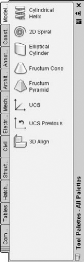
A palette is a window that you can dock or float (like a toolbar). Palettes combine related functions in one place. AutoCAD and AutoCAD LT have several palettes that are covered throughout this book. To see palettes only when you need them, you can auto-hide them. Right-click the palette's title bar and choose Auto-hide from the shortcut menu. To dock a palette, choose Allow Docking from the same shortcut menu. You can dock and auto-hide a palette: Right-click the palette's title bar and choose Anchor Right or Anchor Left. The palette collapses to a thin vertical strip and opens only when you hover the mouse cursor over it. You can also anchor more than one palette on a site. They fit together on the right or left side and unroll to their full length when you hover the cursor over them.
Each of the items on a tool palette is a tool. The tools on the Command Tool Samples tab contain commands that you can use. For example, you can draw a line by clicking the Line tool. The effect is the same as choosing Home tab
Note
You can use tool palettes to insert objects, fill in closed areas, and add other content. For more information, see Chapter 26. I also explain how to customize tool palettes in Chapter 29. For example, you can put custom commands on a tool palette.
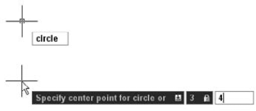
You can execute a command by typing it directly on the command line, directly to the right of the Command: prompt. The command line is a place to enter commands as well as coordinates and values, as shown in Figure 3.2.
The command line is actually a window that you can move like a palette. By default, it is docked at the bottom of the application window. The window usually shows three lines of text, the Command: prompt, where you type, and two lines of text from the previous command. You can drag the top edge of the window to display more than three lines. Commands that you choose from the ribbon, a toolbar button, a menu, or a tool palette are all echoed on the command line.
Tip
By default, AutoCAD and AutoCAD LT display the command line. You can hide the command-line window by using the COMMANDLINEHIDE command, and display it with the COMMANDLINE command, or press Ctrl+9, which toggles the Command window on and off. Another option for the command line is to undock the Command window, right-click the window's title bar on the left, and choose Auto-hide. The Command window collapses to its title bar until you place the cursor over it.

You can use the Dynamic Input feature to execute commands that you type. Dynamic Input displays whatever you type in a tooltip box near the cursor. Dynamic Input also displays prompts at the cursor, so that you don't have to look down at the command line. Note that Dynamic Input does not completely replace the command line; in some situations the command line displays necessary prompts that the Dynamic Input tooltip omits. For more information about Dynamic Input settings, see Chapter 4.
You can turn Dynamic Input on and off by using the Dynamic Input button on the status bar. When Dynamic Input is on, a tooltip box echoes what you type, displays prompts, and then displays your responses at the cursor as you type, as shown in Figure 3.3. This input is echoed on the command line after you press Enter. When Dynamic Input is off, commands and other input that you type appear on the command line only.
All commands have a special one-word command name. This may or may not be the same as the wording that appears on the toolbar's tooltip or on the menu. However, you can be sure of one thing: Every command can be executed by typing its name on the command line or in the Dynamic Input tooltip. Fast typists often prefer to type the command because they find it faster than searching for a command on the ribbon, a menu, a toolbar, or a palette. Most users use a combination of the command line and other user interface options.
Some of the commands are easy to type, such as LINE or ARC. Others are long and harder to remember, such as HATCHEDIT, DDPTYPE, or EXTERNALREFERENCES. Command names such as these can quickly drive you to use one of the user interface elements.
Note
If you like typing commands, you can create short versions of the command names, called aliases. Many are already included with AutoCAD and AutoCAD LT. Aliases are covered in Chapter 29.
You can edit what you have typed on the command line. If you type a long command or a difficult coordinate, and make a mistake, you can backspace up to the mistake and retype the last part correctly. Table 3.1 shows how to use the keyboard edit keys to edit the command line.
Tip
When you start to type a command, and you aren't sure of the exact spelling, you can start typing what you know and then press the Tab key to cycle through all the possibilities in the Dynamic Input tooltip or on the command line. Press Enter when you see the command that you want. This AutoComplete feature works for system variables (which I cover in Chapter 5) and command aliases as well. For example, several commands start with "COPY". You can type copy and then repeatedly press Tab to see these commands.
Table 3.1. Command-Line Editing Keys
Key | Function |
|---|---|
Backspace | Backspaces through the text on the command line, erasing each letter as it backspaces. |
Left arrow | Moves backward through the text of the command, without erasing. |
Right arrow | Moves forward through the text of the command, without erasing. |
Home | Moves the command-line cursor to the beginning of the text. |
End | Moves the command-line cursor to the end of the text. |
Insert | Toggles between Insert/Overwrite modes. Insert mode inserts text. Overwrite mode types over existing text. Note that there is no visual confirmation of which mode you are in. |
Delete | Deletes the character to the right of the cursor on the command line. |
Ctrl+V | Pastes text from the Windows Clipboard. |
You can scroll through and reuse previous command-line entries. To repeat the last line you entered, press the up arrow. Press Enter to execute it. To see more of the command-line entries, press F2 on your keyboard to open the Text Window. Scroll until you find the entry you want, highlight it, and then right-click and choose Paste To CmdLine from the shortcut menu. You now see the highlighted text on the current command line. You can copy selected text from the command-line history or the entire history to the Clipboard. You can also choose Recent Commands from the Text Window's shortcut menu and choose one of the commands from the submenu that appears.
Tip
Switching from the mouse to the keyboard and back is time-consuming. In general, if you're picking points by using the mouse (covered in Chapter 4), using the ribbon and other graphic user interfaces to give commands is faster. If you're typing coordinates as you did in Chapter 1, your hands are already at the keyboard, so typing commands at the keyboard is easier.
When you execute a command by any method, you usually need to respond to the command. AutoCAD displays a prompt that tells you what you need to do next.
The format for command prompts on the command line is as follows:
current instruction or [options] <current value>:
The current instruction explains what you need to do. For example, if you choose an editing command, the prompt usually instructs you to "Select objects." The text in the square brackets lists the various options available for the command. The angled brackets tell you the current value or default option for the command, if any.
In the Dynamic Input tooltip, you first see the following:
current instruction or ↓
If the current instruction is to specify a point, you also see the cursor's X and Y coordinates. Figure 3.4 shows a prompt for the CIRCLE command. After specifying the center of the circle, this command has a current instruction to specify the radius, an option to specify the diameter, and a current value of 1.0000, the radius of the previously drawn circle.
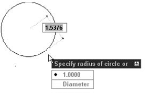
Figure 3.4. To see the options and a current value (if any) in the Dynamic Input tooltip, press the down arrow on your keyboard.
Note
Throughout this book, I show the prompt as it appears on the command line, because this prompt includes the options. If you are looking at the Dynamic Input tooltip, press the down arrow to display the options at the tooltip or right-click to display the shortcut menu.
When you see a prompt, the possible types of responses are as follows:
Specify a point. You can pick a point by clicking with the mouse. You can also enter an X,Y coordinate or displacement — whatever you type appears both in the Dynamic Input tooltip and on the command line. Chapter 4 explains how to specify points.
Enter a value or text. You type the value or the text and press Enter. If Dynamic Input is on, you see your input as you type in the tooltip but you don't see the value on the command line until you press Enter. If Dynamic Input is off, you see your input as you type on the command line.
Select an object. Most editing commands require that you select one or more objects. You can click an object to select it. I explain all the other methods to select objects in Chapters 9 and 10.
Choose an option. Many commands have options that you need to choose before continuing to use the command. To choose an option by using the command line, do one of the following:
Type the one or two letters that are capitalized in the option name — usually (but not always) the first letter(s) of the option. You can type the letter(s) in lowercase. Press Enter.
Press Enter to choose a default option or current value.
Right-click in the drawing area and choose one of the options from the shortcut menu. This works best for options that won't need any numerical input on the command line.
To choose an option by using the Dynamic Input tooltip, press the down arrow on your keyboard to display the options. If there is a default value, you see a mark next to it. Then click one of the options.
At this point, additional options and prompts may appear; you respond in the same way that I have just described, depending on the type of information that the command needs.
In the following exercise, you practice using command options and picking points on the screen with the mouse.
STEPS: Using Command Options
Open a new drawing by using the
acad.dwtoracadlt.dwttemplate. Make sure that the 2D Drafting & Annotation workspace is chosen from the Workspace Switching pop-up list at the right side of the status bar. Close any palettes that may be open.
Look at the command line and the Dynamic Input tooltip. (If you don't see the Dynamic Input tooltip near the cursor, click the Dynamic Input button on the status bar.) You see the following prompt:
Specify start point:
You also see the current coordinate location of the cursor in the Dynamic Input tooltip. Move the mouse cursor anywhere in the middle of the screen, and click to specify the start point. This is called picking a point.
Now you see the following prompts, the first on the command line and the second in the Dynamic Input tooltip:
Specify next point or [Arc/Halfwidth/Length/Undo/Width]:
Specify next point or ↓
Suppose that you want to specify the width of the polyline. Because specifying the next point is the main instruction, right-click to display the shortcut menu and choose Width, which is one of the options. The program responds with the
Specify starting width:prompt. Follow the prompts:Specify starting width <0.0000>:
.5Specify ending width <0.5000>:
.25The prompt to specify the next point returns. Move the mouse so that your cursor is away from the first point that you picked and pick another point. You now see the same prompt repeated.
This time, you want to change the width. To specify the width this time, type w
Specify starting width <0.2500>:
to accept the default value. Specify ending width <0.2500>:to accept the default value again.Move your mouse so that the new segment is at a different angle than the first one. Pick any point on the screen. The same prompt appears again.
Press the down arrow to display the Dynamic Input shortcut menu. Choose Close from the menu. AutoCAD closes the polyline so that you now have a triangle, and ends the command.
Do not save this drawing.
To make working with commands easier, AutoCAD and AutoCAD LT offer shortcuts for repeating and canceling commands as well as sophisticated undo and redo options. You can also use certain commands in the middle of another command.
You can have more than one command in process concurrently, one in each open drawing. You can switch from one open drawing to another without interrupting your commands. For example, if you're in the middle of drawing a circle in one drawing, you can open a new drawing and start another command to get some information you need for the circle. Then you can return to the first drawing and complete the circle.
The most common way to repeat a command you have just used is to press Enter. The most recent command appears again.
Tip
You can also press the Spacebar at the Command: prompt to repeat a command you just used. This technique works well if you want to keep one hand on the mouse and use the other hand to press the Spacebar.
If you know in advance that you'll be using a command several times, you can use another technique — type multiple
Tip
If you create a ribbon or toolbar button that executes a customized set of actions (as I explain in Chapters 29 and 33), right-click and choose the top option of the shortcut menu to repeat the action of the custom button. You cannot press Enter to get this effect.
You may need to use the same input again and again. For example, you may want to draw several circles with the same radius. You can use the recent input list to choose a recently used radius instead of typing it again. You can access recent points, values (such as distances and angles), and text strings.
When you see a prompt for input, right-click and choose Recent Input from the shortcut menu. (In a few instances, no shortcut menu is available, so you can't use this feature.) You can then choose one of the recent input items from the list. You can also press the up or down arrows to cycle through the recent input in the Dynamic Input tooltip.
The Recent Input feature displays items that are appropriate for the current prompt. For example, if the prompt asks for a radius, you don't see angles or X,Y coordinates; you see only lengths.
Sometimes you start a command and then realize you don't need it. In this situation, you can cancel the command and then choose a different command. Press the Esc key to cancel a command that you've already started. The Command: prompt reappears.
In the following exercise, you practice the techniques for repeating and canceling commands.
STEPS: Repeating and Canceling Commands
Start a new drawing by using the
acad.dwtoracadlt.dwttemplate. Make sure that the 2D Drafting & Annotation workspace is chosen from the Workspace Switching pop-up list at the right side of the status bar. Close any palettes that may be open.Choose Home tab

At the
Specify center point for circle or [3P/2P/Ttr (tan tan radius)]:prompt, pick a center point anywhere near the center of the screen.At the
Specify radius of circle or [Diameter]:prompt, type 2Press Enter. The CIRCLE command's first prompt appears again.
Follow these prompts:
Specify center point for circle or [3P/2P/Ttr (tan tan radius)]:
Right-click and choose 2P from the shortcut menu. Specify first end point of circle's diameter:Pick any point on the screen. Specify second end point of circle's diameter:Press Esc.The prompts disappear.
Press the Spacebar. Looking at the Dynamic Input tooltip, you see the
Specify center point for circle or ↓:prompt. Pick any point on the screen.At the
Specify radius of circle or ↓:prompt, press Enter to create another circle with a radius of 2.Do not save this drawing.
Most Windows applications offer Undo and Redo commands. AutoCAD and AutoCAD LT are no different. Some applications remember a list of your last few actions so that you can undo them one by one. AutoCAD and AutoCAD LT remember every command you execute, starting from the time you open a drawing. You can therefore undo every action and return your drawing to its condition when you opened it.
Actually, there are a few obvious exceptions. For example, if you print a drawing, you can't unprint it, and you can't unsave a drawing, either. Similarly, commands that provide you with information, such as the coordinates of a point, cannot be undone.
Note
Some commands have their own undo options. I explain these undo options when I discuss these commands throughout the book.
Everything has been undone
Note
The Undo button on the Quick Access toolbar now allows you to undo multiple operations by clicking the down-arrow to the right of the button and selecting the earliest command that you want to undo. This procedure undoes all commands between the one you select and the top-most command. You can still click the Undo button to undo the most recent command.
When you start the UNDO command, which you enter on the command line, you see the following options:
Enter the number of operations to undo or [Auto/Control/BEgin/End/Mark/Back] <1>:
Enter the number of operations to undo is the default instruction. If you type a number, such as 3, you undo your last three commands. This action is equivalent to clicking the Undo button three times. Table 3.2 explains the other options.
Table 3.2. Options of the UNDO Command
As you undo commands, the command line lists the commands that are being undone. Sometimes, you see the word Group, which means that a group of commands is being undone. However, sometimes the word Group is used even for a single command. This use of the word Group is not significant and can be ignored.
Tip
You can tell AutoCAD or AutoCAD LT to combine consecutive zooms and pans when you undo commands to help you quickly get back to your previous situation. Choose Application Button
Using the Back option when no mark has been created undoes everything you have done in a drawing session! Luckily, you get the following warning message:
This will undo everything. OK? <Y>
Type n
If you undo a command, you might realize that you want to undo the undo. This is called redoing a command. Don't confuse redoing a command with repeating a command. Redoing only applies when you have just undone a command.
Note
Redo on the Quick Access toolbar now allows you to redo multiple undo operations by clicking the down arrow to the right of the button and selecting the earliest command you want to redo. All commands between the one you select and the top-most command are reversed. You can still click the Redo button to redo the effect of the most recent UNDO command.
Note
The MREDO command lets you undo multiple UNDO commands at one time. You can enter it on the command line.
In the following exercise, you practice using the UNDO and REDO commands.
STEPS: Undoing and Redoing Commands
Start a new drawing by using
acad.dwtoracadlt.dwtas the template. Make sure that the 2D Drafting & Annotation workspace is chosen from the Workspace Switching pop-up menu on the right side of the status bar.Choose Home tab
Follow the prompts to draw one line, and press Enter to end the command.
Choose Home tab
Using the default options, pick any three points to draw an arc.
Choose Home tab
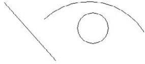
Pick one point to be the center of the circle and another nearby point to specify the radius. Your drawing now contains a line, an arc, and a circle, and looks something like Figure 3.5. Of course, your objects will look different because you picked different points.

Click the Undo button on the Quick Access toolbar; the arc disappears. Click the Undo button again; the line disappears.

Do not save this drawing. If you are continuing, keep the drawing on the screen for the next exercise.
Note
The OOPS command restores the most recently erased object or set of objects, even if you have used other commands in the meantime. See Chapter 18 for further information.
Certain commands can be used within another command. These are called transparent commands. After a transparent command is completed, the original command continues its regular operation. Many transparent commands help you display the drawing differently so that you can complete the original command easily. Other transparent commands change settings. In fact, almost any command that doesn't select objects, create new objects, cause regeneration, or end the drawing session can be used transparently. When you start transparent commands from the ribbon or menus, they are automatically transparent. If you want to type a transparent command on the command line or in the Dynamic Input tooltip, you need to type an apostrophe ( ' ) before the command name.
In this exercise, you practice using transparent commands and two commands concurrently.
Note
The drawing used in the following exercise on using transparent commands and two commands concurrently, abqs-01.dwg, is in the Results folder on the DVD.
STEPS: Using Transparent Commands and Two Commands Concurrently
From the previous exercise, you have a line, an arc, and a circle on the screen. If not, begin a new drawing by using
acad.dwtoracadlt.dwtas the template and draw a line and an arc anywhere on the screen. (You don't need the circle.) Because you haven't saved this drawing, it is calleddrawing1.dwg.Note
If you start a new drawing, make sure that the AutoCAD 2D Drafting & Annotation workspace is chosen from the Workspace Switching pop-up menu on the right side of the status bar. Close any palettes that may be open.
Type zoom
Choose Open from the Quick Access toolbar and open
abqs-01.dwgfrom theResultsfolder on the DVD. This is a drawing of a window from the Quick Start chapter.Choose View tab
Choose Home tab
Command: Specify center point for circle or [3P/2P/Ttr (tan tan radius)]: Pick any point at the center of your screen.
Specify radius of circle or [Diameter]:
At this point, say that you want to see the drawing closer up to properly decide where to place the radius of the circle. Type 'zoom
>>Specify corner of window, enter a scale factor (nX or nXP), or [All/Center/Dynamic/Extents/Previous/Scale/Window/Object] <real time>:
2xResuming CIRCLE command. Specify radius of circle or [Diameter]:Let's say that you want the radius to be equal to the width of the window in your other drawing. Choose View tab
The dimension text clearly states that the window is 3′8″ wide, which is 44 inches.
Choose View tab
Type 44
Close
abqs-01.dwg. Do not savedrawing1.dwg.
Looking carefully at the prompts for the transparent use of the ZOOM command, note three features:
The ZOOM command is preceded by an apostrophe. This is the sign of a transparent command.
The prompt for the transparent command is preceded by
>>. This helps you distinguish between the prompts of the original command and the transparent command that is embedded in it.When the transparent command is complete, the prompt tells you. In this case, you see
Resuming CIRCLE command.
Experiment using transparent commands, and you'll soon find them indispensable.
For the sake of simplicity, this book assumes that you're using a mouse, but some people use a digitizing tablet and a puck (or a stylus). A typical digitizing tablet and puck are shown in Figure 3.6. A puck often has more buttons than a mouse and also has crosshairs on a transparent area that you can use for accurately picking points from a paper drawing.

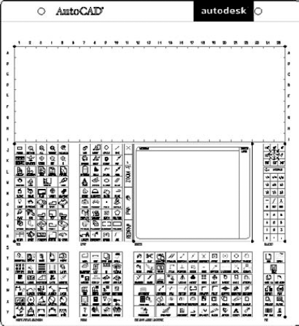
The digitizing tablet is generally configured to include an area that represents the screen you draw on as well as a customizable command area that you use for commands. This command area of the tablet functions as another menu. Figure 3.7 shows the default tablet provided with AutoCAD. (AutoCAD LT has a similar one.) Usually, you would customize the tablet to suit individual needs, as explained in Chapter 33. Each square is equivalent to a toolbar button and executes a command when you click it. The top area is left blank for you to include your own commands. This area is often used to insert parts from a library of standardized parts. Examples would be gaskets and valves in a mechanical drawing environment or doors and windows in an architectural environment.
The square area in the right center represents the drawing area. In this area, the puck functions like a mouse to draw, as well as to access menus and dialog box options. The tablet can also be used for a process called digitizing, which means transferring data from paper into AutoCAD or AutoCAD LT. This transference is often done by putting a paper document directly on the tablet and using the entire tablet as a drawing area. Because the puck has crosshairs on a transparent surface, you can pick points on the drawing, which then become endpoints of lines, for example.
AutoCAD and AutoCAD LT have so many commands with so many options that every user needs help at some time. AutoCAD and AutoCAD LT come with a very complete Help system.
Note
See Appendix B for help that is available on the Internet and other resources for AutoCAD and AutoCAD LT.
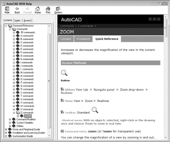
The easiest way to get help on a command is to start the command and press F1. The Help screen for that command opens up. Figure 3.8 shows the screen that opens when you type zoom
Note
After you have opened the Help window one time, when you press F1, it only causes the window to blink on the Windows task bar. Go to the task bar and click the blinking button to open the Help window.
Quickstart links are hyperlinks that you find at selected locations to help you understand a feature or concept. For example, if you choose Plot from the Output tab, the Plot dialog box opens with a link, Learn about Plotting, to more help on plotting. If the feature is new, the link goes to the New Features Workshop, which I cover later in this chapter.
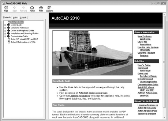
When you have a question, try the Help system. AutoCAD and AutoCAD LT come with the most complete Help documentation I have ever seen in a program. Pressing F1 (with no command active) or clicking the question mark at the right end of the title bar opens the User Documentation window, as shown in Figure 3.9. Click the Show button, if necessary, to display three tabs to the left.
The Contents tab displays help organized by topic. It's like the table of contents of a book. Double-click the icon of a book to open that topic and see subtopics. Click a topic to see it displayed in the right panel. Double-click Command Reference on the Contents tab to get help on commands and system variables. Double-click User's Guide for the "how-to" manual.
If you have an idea in your head but don't know the command name, you may want to use the index. The index is an alphabetical listing of topics. In the text box, type the first few letters of the word or words for which you want help. As you type, the list jumps to the closest match. When you've found the topic you want, highlight it and click Display (or double-click it). Sometimes subtopics appear from which you can choose.
The Help screens have several features that you should know so you can make the best use of them. Many of the topics displayed on the right have three tabs:
Concept. The overall description
Procedure. How to do it
Quick Reference. Related commands and system variables or the documentation of a command, for example, depending on the topic
After you arrive at the Help screen you want, look for links to related topics.
At the top of most screens are several buttons. The selection of buttons depends on which aspect of Help you're accessing. These buttons help you navigate the Help system quickly and easily:
Hide/Show. Hides the left pane so that you can work and look at a Help screen at the same time. When hidden, the button becomes a Show button that displays the left pane.
Back. Returns you to the previous Help screen you viewed.
Forward. Returns you to the Help screen you viewed before you clicked the Back button.
Home. Displays the main Help window.
Print. Prints the topic.
Options. Offers further options such as going to the Home help page and refreshing the screen.
The InfoCenter is a simple way to access Help, the Communication Center, and Favorite resources. This tool is located in the upper-right corner of the AutoCAD or AutoCAD LT window, as shown in Figure 3.10.
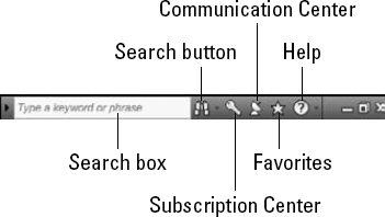
Figure 3.10. The InfoCenter gives you easy access to Help, the Communication Center, and your Favorite resources.
The Search field enables you to enter a search term and get results from the Help files and the New Features Workshop. Enter one or more terms and press Enter. The results drop down, and you can choose the item you want in order to open it in the Help window.
Tip
You can add your own resources to search through those, as well. Click the down arrow to the right of the Search button and click Add Search Location to browse to files on your computer or network. You can add resources from the following file types: TXT, DOC, CHM, HLP, HTML, HTM, PDF, and XML. This is a great place to reference your CAD Standards Manual and/or those of your clients. From the same down arrow, you can choose Search Settings to specify which of the standard resources you want to search, depending on your needs.
The Communication Center tool in the InfoCenter shows Live Updates (software updates), subscription announcements and lessons (for subscription members), articles, and tips. It also displays RSS feeds of the knowledge base, blogs, and the discussion group. You can customize the settings. For more information, see Chapter 26.
These are quick links to items that you have tagged as useful. You can tag these items from your Search results or in the Communication Center drop-down list. To the right of each item is a white star. Click the star to turn it yellow and add it to the Favorites list.
In this exercise, you practice using the Help system.
STEPS: Using AutoCAD Help
If AutoCAD or AutoCAD LT is not open, start the program with the
acad.dwtoracadlt.dwttemplate. If the program is already open, you can do this exercise with any drawing on the screen. Make sure that the 2D Drafting & Annotation workspace is chosen from the Workspace Switching pop-up menu on the right side of the status bar. Close any palettes that may be open.Choose Home tab
Click 2P (Two Points), which appears underlined. The 2P description appears. Read the description of the 2P option.
Click the Close button at the top-right corner of the Help window. Press Esc to cancel the CIRCLE command.
Click the Help (question mark) button on the right side of the title bar. If the left, tabbed pane does not appear, click the Show button in the Help window.
Click the Contents tab if it is not on top. Double-click User's Guide. From the list, double-click
The User Interface.Click
Other Tool Locations, and then clickShortcut Menus. Read the text in the right pane.Click the Procedures tab in the right pane of the Help window. Click the To Display a Shortcut Menu link and read the text.
On the left side of the Help window, click the Index tab.
In the text box at the top, type transparent commands. (Don't press Enter.) Double-click the
Transparent Commandsitem.From the Topics Found window, double-click the
Enter Commands on the Command Lineitem.In the right pane, scroll down until you see the
Interrupt a Command with Another Command or System Variableitem and read the text.In the left pane, click the Contents tab again. Scroll down and double-click Command Reference, then double-click Commands.
Double-click C Commands, and then click CIRCLE. You see the Circle Help screen again. You can find help on any command from the Command Reference. Close or minimize the Help window.
In the AutoCAD InfoCenter window, type transparent commands in the Search text box and press Enter. Choose
Enter Commands on the Command Line (Concept). If necessary, click the Help button on the Windows task bar. You should see the same content that you saw previously.Click the Close button of the Help window.
In this chapter, you read all you need to know about how to use AutoCAD and AutoCAD LT commands. Specifically, you read about:
Using the ribbon
Using menus and shortcut menus
Using dialog boxes
Working with toolbars
Using tool palettes
Understanding command names
Using and editing the command line
Using the Dynamic Input tooltip to enter and respond to commands
Responding to command options and using the command line and shortcut menus
Repeating and canceling commands
Undoing and redoing commands
Using transparent commands
Using a puck and digitizing tablet to enter commands
Getting help
In the next chapter, I explain how to specify coordinates, an essential skill before you start to draw.