
When you create a drawing, you not only create objects, but you also create a complex structure to support those objects. You create named blocks, layers, layouts, text styles, dimension styles, and linetypes to help define those objects. And you spend a lot of time creating them! All these named drawing components can be reused and organized for greater efficiency, using the DesignCenter.
Tool palettes are a multifaceted solution that enables you to execute commands, as well as to insert hatches and blocks. You can also insert tables, xrefs, images, gradients, and more.
Having standards for named drawing components, such as layers and text styles, is important for consistency and readability. AutoCAD offers a comprehensive system for maintaining CAD standards. Security is also important, and AutoCAD offers excellent features to help you with this. AutoCAD LT does not contain all these features.
Sheet sets enable you to manage sets of drawings. You can automate the placement of viewports, as well as view and call out labels. You can plot or publish sheet sets as one group. AutoCAD LT does not offer the sheet set feature.
You also need to keep track of your drawings and make sure that they're accessible. Archiving and repair procedures are important in any CAD environment. This chapter covers all these topics to help you keep control of your drawings and their content.
I mention the DesignCenter many times in this book — for example, in Chapter 11 on layers and Chapter 18 on blocks. In this chapter, I cover the DesignCenter in detail. You can use the DesignCenter to easily drag named drawing components from one drawing to another. You can even drag raster images directly into your drawing. You can access this drawing content from drawings on your hard drive, on a network drive, or over the Internet. You never need to re-create them.
You can do the following with the DesignCenter:
Browse and insert named drawing components, including blocks (and dynamic blocks), xrefs, layers, text styles, table styles, dimension styles, linetypes, and layouts. You can also access custom objects that are created by third-party applications.
Create shortcuts to drawings and locations that you use most often.
Search for drawings and named drawing components.
Open drawings by dragging them into the drawing area.
Create tools for your tool palettes.
View and insert raster image files by dragging them into the drawing area.
Note
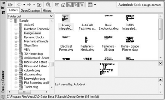
While the DC Online allows you to insert blocks from the Internet, the catalog is very limited. The Autodesk Seek Web site offers a large catalog of symbols and specifications that you can use in your drawing. Click The Autodesk Seek logo in the upper-right corner of DesignCenter or use the Content panel on the Insert tab.
The Folders tab displays a tree view of any location — your hard drive, network, or the Internet — that you can access. This tree view is very similar to that of Windows Explorer. Click the plus sign next to a drive or folder to display its contents. Use the vertical scroll bar to display any location.
A selected drawing displays its named components in the content area on the right side of the palette. (Use the Views drop-down list to choose the type of display that you want.) You can also click the plus sign next to a drawing to display these components in the tree view. Then click a component type, such as blocks, to see a list of the blocks in the drawing, as shown in Figure 26.1. Click Preview on the DesignCenter toolbar to see a preview in the preview pane of blocks, drawings, and raster images. Click Description to display a description, if one is saved.
What do you do if you don't know the location of the drawing that you want? Suppose you know the name of the layer but not the name of the drawing that contains that layer. The DesignCenter includes a Search feature to help you.
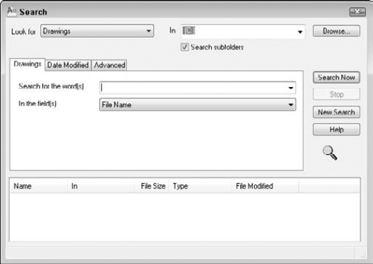
Here's how to use the Search window:
Click the Look For drop-down list to choose what you're looking for. You can look for blocks, dimension styles, drawings, drawings and blocks, hatch pattern files, hatch patterns, layers, layouts, linetypes, table styles, text styles, and xrefs.
Click the In drop-down list to specify the drive that you want to search. By default, the Search subfolders check box is checked so that the search looks in all folders and subfolders within the drive.
Use the tabbed area to specify the name of the components that you want. The tab's name and content change, depending on what you chose in the Look For drop-down list. For example, if you chose Layers, the tab is called Layers and asks you for the name of the layer. If you're looking for drawings, you have three tabs to work with:
The Drawings tab enables you to look for a drawing by filename (the default), title, subject, author, or keywords. Choose one of these options in the In the Field(s) drop-down list. Then type the text that you want to look for in the Search for the Word(s) text box. You can use the wildcards * (to substitute for any number of characters) and ? (to substitute for any one character). Specifying a drawing's title, subject, and keywords is discussed later in this chapter.
The Date Modified tab enables you to search by the last date that the file was saved or modified. You can specify a range of dates, or look in the last x days or months.
The Advanced tab enables you to search for text in drawing descriptions, block names, attribute tags, and attribute values. You can also search here by drawing size.
When you've created your specifications, click Search Now.
Note
See Chapter 18 for information on creating block descriptions when you create a block. The main reason for creating a block description is to display it in the DesignCenter and use it in a search on the Advanced tab, as just described.
For more information on searching for drawings, see the section "Finding drawings" later in this chapter.
The Favorites folder is a Windows convention that helps you to find files that you use often. This folder contains shortcuts to actual files. The files remain in their original locations. You'll find an Autodesk subfolder within the Favorites folder where you can store shortcuts to drawings and other files that you use often. You can then easily open the Favorites folder and find these files. Favorites is one possible place to keep drawings that contain block libraries.
To add a shortcut to Favorites, right-click the drawing (or other file) in the DesignCenter and choose Add to Favorites.
Warning
If you right-click in the Content pane and choose Add to Favorites, the DesignCenter adds a shortcut to the entire content of the folder. This is great for adding all the items in a folder at once, but if you do it inadvertently, you could end up with more files than you want in Favorites. To add one item, remember to select it first.
To move, copy, or delete shortcuts from Favorites, right-click the content pane and choose Organize Favorites.
As soon as you have the item that you need in the Content area, you need to insert it into your drawing. If you used the Search window to locate a file, then you can also insert directly from the results that you find. You can either drag the item onto the drawing area or right-click it and choose an option. Sometimes these two methods provide slightly different results. In this section, I explain how to insert drawing components into your drawing.
You can insert an entire drawing into your drawing. Choose the drawing's folder in the navigation pane so that the drawing appears in the content area. Drag the drawing's icon onto the drawing area. The command line prompts you for an insertion point, scale, and rotation angle, using the -INSERT command (the command-line version of the INSERT command).
If you right-click the drawing, you can choose to insert the drawing as a block, or attach it as an xref.
You can open a drawing by using the DesignCenter. Display the drawing in the content pane, right-click it, and choose Open in Application Window. The drawing opens, keeping your current drawing open as well.
In Chapter 5, I explain that you can use the Units dialog box (choose Application Button
You can insert blocks in two ways:
If you drag the block's icon onto the drawing area, the drawing uses Autoscaling, which compares the current drawing's units with those of the block, and scales the block appropriately, using the value set in the Units dialog box. The block takes on the default scale and rotation.
If you double-click the block's icon or right-click it and choose Insert as Block, the Insert dialog box opens, where you can specify the insertion point, scale, and rotation.
A raster image is a bitmap graphic file. You can insert raster images directly into your drawing. To attach a raster image, drag its icon onto the drawing area. The command line prompts you for an insertion point, scale, and rotation angle.
Note
See Chapter 27 for more information on raster images, including determining which type of files you can import, attaching images, clipping images, and controlling how they're displayed.
Tip
Knowing the appropriate scale of an image before inserting it is often difficult. When you move the cursor at the Specify scale factor or [Unit] <1>: prompt, you can see a bounding box that will help you visualize the resulting size of the image.
To attach or overlay an xref, right-click its icon and choose Attach as Xref to open the Attach External Reference dialog box. Choose either Attachment or Overlay in the Reference Type section. Specify an insertion point, scale, and rotation (or choose to specify them on-screen), and click OK.
If you drag the xref onto the drawing area, you see prompts on the command line that are similar to those of the INSERT command.
To insert a layer, layout, linetype, text style, table style, or dimension style into a drawing, drag its icon onto the drawing area. Of course, these items don't appear in your drawing area, but they're added to the drawing's database.
You can drag multiple items at one time. To select a contiguous group, click the first item, press and hold Shift, and click the last item. To select individual multiple items, click the first item, press and hold Ctrl, and click any other item that you want to insert. You can also double-click an item to insert it.
Warning
The insertion process does not check for duplicate layer names. If you try to insert a layer with the same name as a layer in your current drawing, you see a message: Layer(s) added. Duplicate definitions will be ignored. You should check for duplicate layer names before trying to insert layers from the DesignCenter.
The DesignCenter provides several controls that help you manage its display.
Tip
If you have old blocks that don't have preview icons, use the BLOCKICON command and press Enter at the first prompt to automatically create preview icons of all the blocks in a drawing.
If you make changes in the structure of a folder while the DesignCenter is open — for example, by deleting a drawing by using Windows Explorer — right-click the navigation or content pane and choose Refresh. The DesignCenter re-reads the data and refreshes the list.
To dock the DesignCenter, right-click the title bar and choose Allow Docking. Then choose Anchor Left or Anchor Right to dock it to the left or right of your drawing window. To collapse the DesignCenter down to its title bar when you're not using it, right-click the title bar and choose Auto-Hide; whenever you move the mouse cursor off the DesignCenter, it collapses. Just move the cursor back onto the title bar to expand it again. You can anchor the DesignCenter at the same side as other palettes; its title bar becomes shorter to fit. When you expand it, it rolls down to its full length. To avoid unwanted docking, either uncheck Allow Docking on its title bar or press Ctrl as you drag. These instructions apply to all palettes in AutoCAD and AutoCAD LT.
Note
The drawings used in the following exercise on using the DesignCenter, ab26-a.dwg and ab26-b.dwg, are in the Drawings folder on the DVD.
STEPS: Using the DesignCenter
Open
ab26-a.dwgfrom the DVD.Save the file as
ab26-01.dwgin yourAutoCAD Biblefolder. This drawing needs an updated set of layers and a titleblock. It is shown in Figure 26.3.Choose View tab

In the navigation pane, locate
ab26-b.dwgon the DVD. Click its plus sign.Choose Blocks. The
ansi_dblock appears in the content pane. Double-clickansi_d. Uncheck all Specify On-screen check boxes and click OK.Do a Zoom Extents.
In the navigation pane, click Layers for
ab26-b.dwg.In the content pane, click the first layer, press and hold Shift, and click the last layer to select all the layers. Drag them onto the drawing area to import the layers.
Save your drawing.
The Tool Palettes window is a tabbed palette that can contain drawings, blocks, hatches, images, gradients (AutoCAD only), drawing objects, xrefs, tables, and commands. By default, the Tool Palettes window contains over three dozen tabs in AutoCAD and ten tabs in AutoCAD LT with sample content and commands. Each tab is considered a separate tool palette within the main Tool Palettes window. Figure 26.4 shows the default Tool Palettes window with the Draw tab on top. To open the Tool Palettes window, choose View tab
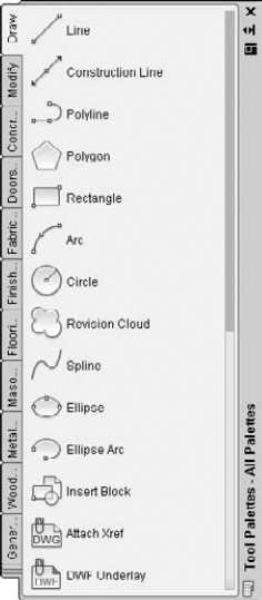
Figure 26.4. The standard Tool Palettes window has many tabs, each with a different category of commands or insertable content.
The tool palettes are meant to be customized with your own content. You can easily create new tabs with your own blocks and other types of content, objects, or commands. After you create the tab, you can drag the items into your drawing. A tool is any item on a tool palette, and is represented by an icon.
Note
Because there are so many tabs, several of the tabs overlap together at the bottom so that you can't see their titles. When you click these tabs, a menu pops up, listing the names of all the tabs. Click the tab that you want from the menu to display that tab. Materials used for rendering are on several palettes; other palettes contain visual style, light, and camera tools.
When you create a new tool palette, you add a tab to the Tool Palettes window. To create an empty tool palette, right-click in the Tool Palettes window and choose New Palette. A label appears so that you can name the tool palette. Type the name and press Enter. When you have a new tool palette, you're ready to add tools to the palette, as I explain in the following sections.
Note
You can also create a new, empty tool palette by using the Customize dialog box. See Chapter 29 for details.
You can add descriptive text and separator bars to any tool palette. For example, you can include instructions that explain a tool and organize commands into groups by using separator bars. To add text or separators, right-click any tool palette and choose Add Text or Add Separator from the shortcut menu.
The easiest way to create a new tool palette is from the DesignCenter, discussed in the previous section of this chapter. When you use this method, you simultaneously create not only the tool palette but also its contents. To create a new tool palette, follow these steps:
Open the DesignCenter.
In the tree view or content area, navigate to a folder, drawing file, block icon, graphic image file, or hatch icon.
Right-click the item and choose Create Tool Palette.
If you select a folder or drawing, choose Create Tool Palette of Blocks.
If you select a hatch file (
*.pat), choose Create Tool Palette of Hatch Patterns.After a few seconds, the new tool palette tab displays, showing each drawing, block, or hatch on the tab:
If you chose a folder, the tab includes all drawing files in the folder.
If you chose a drawing file, the tab includes all blocks in the drawing.
If you chose a block icon, the tab includes the block.
If you chose a hatch pattern file, the tab includes all hatch patterns in the PAT file. (See Chapter 31 for more information about creating hatch patterns in
.patfiles.)If you chose a hatch icon, the tab includes the hatch pattern.
Another way to add content tools is to drag content directly from an open drawing. This method is the only way to add gradients to a tool palette, but it works with any other type of content as well. Just select the object, then click and drag it onto the tool palette. The tool palette assigns a name, but you can change it to anything you want. Right-click the tool and choose Rename. Type the new name and press Enter.
Tip
You can drag content over a tab that is not on top; that tab then becomes active so that you can add the content to it.
When you drag content from your drawing, you're creating a tool by example. The properties of the tool match those of the object in your drawing. For example, if you drag a hatch on layer object onto a tool and then use that tool to hatch a closed object in your drawing, you create a hatch on layer object.
You can add commands to tool palettes. You choose your method depending on the amount of customization that you want and how you want to organize your commands. You can add commands by dragging objects from a drawing or by dragging commands from the Commands List pane in the Customize User Interface Editor (covered in Chapter 33).
You can drag drawing objects, such as circles, text, and so on onto a tool palette. AutoCAD creates a command tool that draws an object with the same properties as the original object. For example, if you regularly need to enter text on the Annotation layer by using the Annotation text style, select some existing text with those properties, and drag it onto a tool palette. The tool is now called simply MText. Right-click, choose Rename, and enter Annotation or another meaningful name. This command tool contains the properties of the object that you used.
Note
When you click the selected object to start dragging it, don't click it on the grip handles. When you click, after a moment you'll see the drag-and-drop arrow cursor, and then you can drag the object to the tool palette. To drag a table, you must drag-and-drop with the right mouse button; otherwise, you simply select one of the table cells.
When you create certain types of command tools, the tool palette recognizes the command as one of a group of commands, and creates an entire group, or flyout, of command tools that all use the same properties as the original. This technique works with dimensions and common drawing geometry objects, such as lines and circles. Note, however, that the tool palettes include these flyouts by default.
Note
If you are using the AutoCAD Classic or AutoCAD LT Classic workspace, you can drag toolbar buttons onto a tool palette. Choose Manage tab
You can copy an existing tool to create a new tool, whether a content tool or a command tool. You can then change the tool properties. You can use this technique to create related, but slightly different, tools. For example, you could include a hatch on two different layers. You could also include variations of a dynamic block.
To copy a tool, right-click the tool and choose Copy from the shortcut menu. Then right-click again and choose Paste. The next section explains how to change tool properties.
Each tool on a tool palette has properties that you can set. The available properties vary slightly, depending on the type of tool. The properties specify how that tool is inserted into a drawing. Tools inherit their properties from the object that you dragged onto the tool palette. However, you can change the properties. To set the properties of a tool, right-click it and choose Properties to open the Tool Properties dialog box. Figure 26.5 shows the Tool Properties dialog box for a hatch pattern.
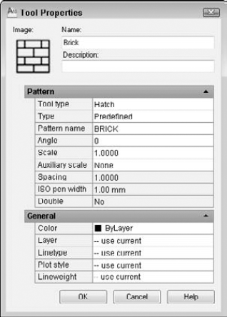
The middle section of the dialog box contains Insert, Attach, or Pattern properties (depending on the type of content), and the bottom section of the dialog box displays General properties.
To specify any property, click the rightmost column for that property. Either type a new value or choose from the drop-down list. After you're done, click OK to close the Tool Properties dialog box.
Tip
You can select multiple tools and change their common properties at one time. To select multiple tools, hold down the Ctrl key and click the tools that you want to change.
The tools that you create by dragging content from a drawing take their properties from that object, so they may contain an inherent scale. For example, your hatches, blocks, and xrefs have a certain size. If you need to adjust a scale, you can do so, based on one of the following:
To set the scale of a hatch, block, or xref tool, right-click the tool and choose Properties. Click the Auxiliary Scale item. Then click the down arrow that appears at the right, and choose either Dimscale or Plot Scale. Click OK. From now on, the block or xref comes into your drawing at the scale that you've set in your drawing.
You can change the order of tool palettes (tabs) in the Tool Palettes window, and you can change the order of tools on a palette.
To move a tool on a palette, drag the tool. A horizontal cursor appears to show you where the tool will go.
To move a palette, right-click the tab itself and choose Move Up or Move Down.
You can also move or copy a tool (drawing, block, or hatch) from one tool palette to another. Follow these steps:
Display the tool palette (tab) that contains the item that you want to move.
Right-click the item and choose Cut (to move it) or Copy (to copy it).
Display the tool palette (tab) where you want to place the item.
Right-click any blank area on the tab and choose Paste.
You can use this method to consolidate tabs or reorganize the tools on a tab.
To delete a tool palette, right-click the palette and choose Delete Palette. A warning message is displayed, explaining that you cannot recover the deleted tool palette unless you export it to a file. To delete a tool on a tool palette, right-click the tool and choose Delete. Here, too, you need to confirm the deletion when a warning message appears.
To export a tool palette, save it to a file. You can then share tool palettes with others. You import and export tool palettes in the Customize dialog box. See "Customizing Tool Palettes" in Chapter 29 for details.
To rename a tool palette, right-click the palette and choose Rename Palette. To rename a tool, right-click the tool and choose Rename. In both situations, type a new name and press Enter.
If the source of a tool changes, its icon does not automatically change to match. In this situation, the icon will not accurately represent its tool. To update an icon, use one of the following methods:
Right-click the tool and choose Properties. Click the Source File (or Pattern Name) item, then use the Ellipsis button to choose any other file, block, or hatch pattern, and then immediately choose the correct item again. This technique updates the icon for the tool.
Delete the tool and reinsert it.
If you change a block or dynamic block, you can update its image. Right-click the image and choose Update Tool Image from the shortcut menu.
Note
You can specify any image for a tool. Perhaps you want to create your own image. Most images are 32 × 32 pixels. To specify an image, right-click the tool and choose Specify Image. Choose the image you want, and click Open. To find the location of the ToolPalette folder, use the OPTIONS command to open the Options dialog box. On the Files tab, expand the Tool Palettes File Locations item.
If you move the source file for a tool, you need to update the tool with the new location:
Right-click the tool and choose Properties.
In the Tool Properties dialog box, use the Ellipsis button to choose the file again.
Click OK.
To work most comfortably with the Tool Palettes window, you can adjust its display options. These options are the same as for the DesignCenter, discussed previously in this chapter. An additional option, Transparency, opens the Transparency dialog box. When the tool palette is transparent, you can see the drawing through it. You can specify the amount of transparency or turn it off. Then click OK.
Note
Transparency is available only when hardware acceleration is off (which it is by default). Hardware acceleration is governed by your computer's video card and helps to speed up the display. If you want to use the transparency feature, you can use software acceleration instead (and see if it affects your display speed). Choose Application Button
Right-click any blank area of a tool palette and choose View Options to open the View Options dialog box. You can change the size and layout of the tool icons on a tool palette. Use the slider to change the size of the icons. You can choose to apply the changes to the current tool palette or to all tool palettes. Choose from the following display styles:
Icon only. You see the icon displaying the drawing, block, or hatch, but no text.
Icon with text. Text is displayed beneath each icon, and the icons are arranged in columns. This option displays much more on a tab than the list view.
List view. You see one column of icons, with the text to the right of each icon.
Click OK when you're done.
You may have one set of tool palettes for architectural work and another for mechanical work. For whatever reason, you may want to display one set of tool palettes at one time and another set at another time. For this purpose, you organize tool palettes into groups. I explain how to create these groups in Chapter 29.
To display the various groups, right-click the title bar of the tool palette and choose the group that you want. Using groups helps to avoid clicking through too many tool palettes. After all, the point is instant access. However, you can always display all the palettes by right-clicking and choosing All Palettes.
Inserting a tool from a tool palette is as simple as dragging the tool onto the drawing area. The tool is inserted by using the properties specified in the Tool Properties dialog box (discussed previously in this section).
Tools know how to behave. Drag a gradient or hatch into an enclosed area and it automatically fills the area. Drag an xref onto a drawing and you get a prompt, at the command line, for the insertion point. Tools automatically use their properties so that you get a circle on its proper layer or a hatch with the proper scale.
If you want the flexibility to insert a block or hatch with more than one setting, you can insert another copy of the item onto a tool palette. For example, you can place two copies of a hatch pattern on a tool palette and set their properties to different spacing. You would then rename the tools to make the differences clear (for example, lightning1 and lightning 2). You can also copy a tool and then modify it, as I explain in the section "Copying a tool" earlier in this chapter.
Tip
You can use the TPNAVIGATE command on the command line to display a tool palette or group, if you know its name. This command is especially useful for programming purposes.
Note
The drawings used in the following exercise on creating and using a tool palette, ab26-c.dwg and ab26-d.dwg, are in the Drawings folder on the DVD.
STEPS: Creating and Using a Tool Palette
Open
ab26-c.dwgfrom the DVD.Save the file as
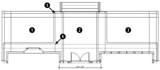
ab26-02.dwgin yourAutoCAD Biblefolder. This drawing, shown in Figure 26.6, needs some blocks and a hatch pattern inserted. You'll also add a dimension.Choose View tab
Choose View tab
Right-click any empty area of the tool palette, and choose New Palette. A label appears. Type 2d arch and press Enter. You now have a new tool palette named
2d arch.Note
If the tool palette is collapsed when the mouse cursor is not over it, right-click its title bar and choose Auto-Hide to uncheck this item.
From the content area of the DesignCenter, drag each of the blocks to the new tool palette. An icon appears on the tool palette for each block.
In the Folder List of the DesignCenter, navigate to
acad.patoracadlt.pat, which contains hatch patterns. Clickacad.patoracadlt.patto display the hatch patterns in the content area.Note
To find the location of
acad.patoracadlt.pat, choose Application ButtonDrag User Defined, one of the hatch patterns, to the tool palette. (This hatch pattern is equivalent to choosing User Defined as the Hatch Type in the Hatch and Gradient dialog box. See the section "Creating Hatches" in Chapter 16 for details.) The tool palette now has three items on it. Close or Auto-Hide the DesignCenter.
Right-click the User-Defined Hatch icon and choose Properties to open the Tool Properties dialog box. You want to specify settings so that this hatch pattern will look like scored concrete for the porch floor.
In the Tool Properties dialog box, make the following changes and then click OK:
For the Angle, type 45.
For the Spacing, type 2' (or 24).
Click the Double item at the bottom of the Pattern section and then click the arrow at the right side of the row. Choose Yes from the drop-down list.
Click the Layer item in the General section and choose FLOOR from the drop-down list. (You may have to drag the bottom edge of the dialog box down to see the layer item.)
Right-click the hatch tool and choose Rename. Type porch tile and press Enter.
Drag the Porch Tile hatch icon to

Choose the Command Tool Samples tab and click the small arrow to the right on the Linear Dimension tool to see the flyout. (If you don't see the Command Tool Samples tab, click the overlapping tabs at the bottom of the palette window and choose Command Tool Samples from the list of tabs.) To place a linear dimension, click the main linear dimension icon. Follow the prompts:
Specify first extension line origin or <select object>:
Pick the upper-left corner of the porch. Specify second extension line origin:Pick the upper-right corner of the porch. Specify dimension line location or [Mtext/Text/Angle/Horizontal/Vertical/Rotated]:Pick any location for the dimension line above the steps.Choose View tab
Switch back to the 2d arch tab and click the Post icon. At the
Specify insertion point:prompt, pick the intersection at
Click the Post icon. At the prompt, pick
Right-click the tool palette's title bar. If Allow Docking is checked, click Allow Docking to uncheck this item. If Auto-Hide is not checked, click Auto-Hide to enable this feature. Move the mouse off the tool palette. The tool palette collapses to its title bar. Move the tool palette to the right side of your screen.
If you're working on someone else's computer, you should delete the tool palette. Move the cursor over the palette to display it. Right-click any blank area and choose Delete Palette. Click OK to confirm the deletion.
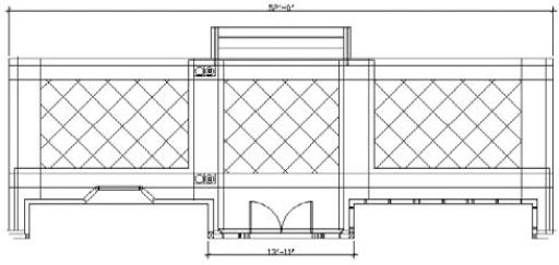
Save your drawing. It should look like Figure 26.7.
One person rarely has complete control over a drawing. You may xref in other drawings, or others may xref in your drawings. Several people may work on one drawing. You may send a drawing to a client who may work on it as well. Working on a drawing is usually a collaborative effort — and it can get out of control.
One way to maintain control is to set standards for drawings, and issue those standards so that everyone involved has access to them. If you don't have agreed-upon standards, you not only waste time changing layers, text styles, and so on, but your drawings become very complicated. You should set standards for the following:
Drawing names and property summaries
Blocks, including names, layers, and insertion points
Layers, including uses, names, colors, linetypes, and lineweights
Table styles
Dimension styles and tolerances, if any
Multileader styles
Multiline styles
Units settings
Plot styles
Layouts
In some cases, your standards are set by outside conventions. For example, the American Institute of Architects (AIA) and the Construction Standards Institute (CSI) publish layering standards for members.
The CAD Standards tools facilitate the process of checking drawings against standards. You can check the following in a drawing:
Layers
Text styles
Linetypes
Dimension styles
Note
The CAD Standards feature is not available in AutoCAD LT.
AutoCAD checks for both names (such as layer names) and properties (such as layer color and linetype).
Here's the general procedure for setting and maintaining standards with the CAD manager's tools:
Create a standards file (
*.dws).Associate the standards file with a drawing or template.
Test the drawing against its standards file.
You can test drawings against a standards file one by one (interactively) or as a group (batch auditing).
You use a standards file to set standards for drawings. A standards file has a filename extension of .dws. Unlike many of the support files used in AutoCAD, a standards file is not a text file; rather, it is similar to a drawing file. You create a standards file by creating a drawing that contains the standards — layers, linetypes, text styles, and dimension styles — that you want.
To create a standards file from scratch, follow these steps:
Choose Application Button
Choose a template, or click the Open button's down arrow and choose one of the Open with No Template options.
Create the layers, linetypes, dimension styles, and text styles that you want to place in the standards file.
Choose Application Button
In the Save In drop-down list, choose a location for the file.
Click Save to save the drawing standards file.
You can use an existing drawing for your standards file (in fact, this method is probably easier). However, be careful to purge all layers, linetypes, dimension styles, and text styles that you don't want. (I discuss the PURGE command in Chapter 11.)
As soon as you have your standards file, you associate it with a drawing or template that you want to check, using the STANDARDS command.
Tip
If you use a template to start new drawings, open the template and associate the standards file with your template. Then every drawing that you start based on the template is associated with the standards file.
To associate a standards file with the current drawing, follow these steps:

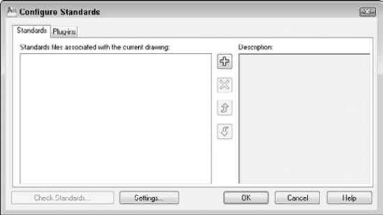
On the Standards tab of the Configure Standards dialog box, shown in Figure 26.8, click the + button.
In the Select Standards File dialog box, choose the standards file that you want to use and click Open. You can associate more than one standards file with the drawing; continue to click the + button and choose more standards files.
Click the Plug-ins tab and click any standards that you don't want to check. All four standards types — Dimension Styles, Layers, Linetypes, and Text Styles — are initially checked. (The choices that you make persist for future standards checks until you change them.)
Click OK to close the Configure Standards dialog box and return to your drawing.
Note
If you just finished associating a standards file with a drawing, you can click Check Standards in the Configure Standards dialog box.
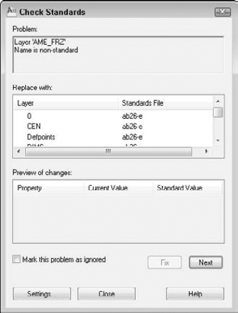
Figure 26.9. The Check Standards dialog box guides you through the process of checking a drawing against a standards file.
The Check Standards dialog box lists all the problems — items in the drawing that don't match the standards file — that it finds, one by one. Here's the procedure for using this dialog box:
You see the first problem in the Problem section of the dialog box.
Use the Replace With section to choose a replacement for the nonstandard item. This section contains all eligible replacements according to the standards file.
Look at the Preview of Changes section to see how the replacement will affect your drawing.
To make the replacement and standardize your drawing, click the Fix button.
To ignore the problem and go on to the next one, click the Next button.
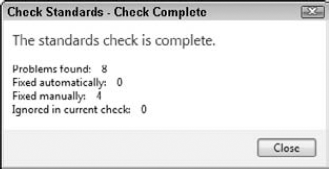
AutoCAD continues to display problems that you can fix or ignore. After you're done, you see the
Checking is completemessage, along with a short report explaining how all the problems were handled, as shown in Figure 26.10. You can click the Next button again to recheck the drawing.
For information on batch checking (checking standards for many drawings at once), see the "Checking standards for multiple drawings" sidebar in this chapter.
When you fix nonstandard objects — for example, layers or linetypes with nonstandard names — AutoCAD purges these objects from the drawing. For example, after you change the layer Layer1 to the layer Notes, objects on Layer1 are changed to the layer Notes, and Layer1 is purged.
You can specify how the CAD standards feature functions to provide real-time notification and automatic repair. To specify CAD standards settings, choose Manage tab
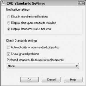
Figure 26.11. Use the CAD Standards Settings dialog box to specify how you want CAD standards checking to work.
In the top section, Notification Settings, choose one of the following:
Disable standards notifications. No real-time notification of standards violations. You can still check standards by using the Check Standards dialog box at any time.
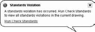
Display alert upon standards violation. Displays a message if your drawing is associated with a standards file and you make a change that puts the drawing in noncompliance with the standards file, as shown in Figure 26.12.
Display standards status bar icon. Displays an icon on the AutoCAD status bar. The icon has an exclamation point if there is a nonstandard object in the drawing. A balloon appears to notify you that a standards violation has occurred. Click the Run Check Standards text or the icon to open the Check Standards dialog box so that you can fix the problems.
Checking standards for multiple drawings
What do you do if you want to check standards for hundreds of drawings at once? For this scenario, AutoCAD has created Batch Standards Checking, shown here. Here's how to use the Batch Standards Checker:
From the Windows task bar, choose Start
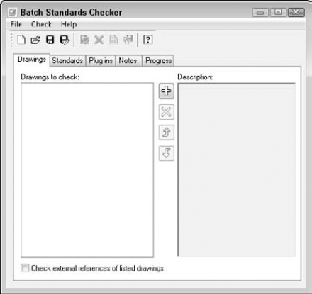
On the Drawings tab, click the + button and select the drawings that you want to include. Click Open. After you click Open, you can click the + button again and add drawings from a different folder. Use the Remove Drawing (Delete) button to delete drawings and the Move Up and Move Down buttons to change the order of the drawings. If you also want to check external references, check the Check External References of Listed Drawings check box. Note that you can't check password-protected drawings.
On the Standards tab, choose to check each drawing against its associated standards file if you have associated standards files for all your drawings. Otherwise, choose to check the drawings against the standards file(s) that you select. To select a standards file, click the + button, choose a standards file (
.dws), and click Open.On the Plug-ins tab, choose the standards that you want to check. This tab is the same as the Plug-ins tab of the Configure Standards dialog box, discussed earlier in this section.
Click Save on the Batch Standards Checker toolbar. In the Batch Standards Checker - File Save dialog box, save the standards check file. A standards check file (
.chx) contains information about which drawings and standards files you're using for the batch standards check. AutoCAD gives the file a default name, but you can change the name if you want.
In the bottom section, Check Standards Settings, check Automatically Fix Non-standard Properties to automatically fix noncompliant drawings. Automatic fixing applies only to a situation where a drawing object has a name that matches a standard but has different properties. For example, if a standards file contains a layer named OBJ that has a blue color and the current drawing has an object on the OBJ layer that is red, the object will be changed to blue to match the color of the OBJ layer in the standards file.
Check Show Ignored Problems to display any problems that were not fixed in the standards check report.
From the Preferred Standards File to Use for Replacements drop-down list, choose a standards file to use by default in the Replace With section of the Check Standards dialog box. This standards file is used only if you choose to automatically fix nonstandard properties and the associated standards file, because the drawing does not provide a suitable replacement.
Layers are an important part of maintaining drawings standards. Many people have strict rules about which layers are allowed in a drawing. Xrefs can be especially troublesome in this regard, because layers from the external drawings are added to your drawing. AutoCAD can notify you when new layers are added to a drawing. This notification is based on the layers existing when you open the drawing, not on a standards file.
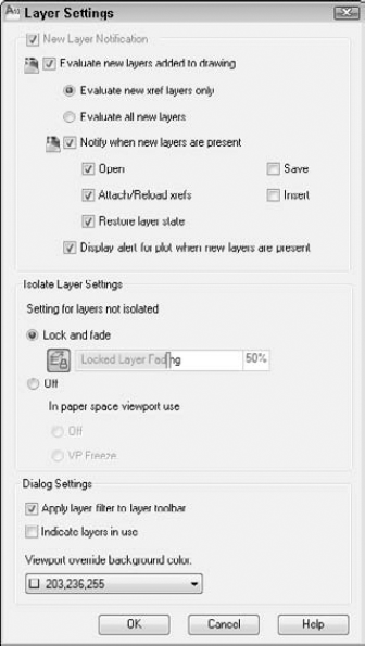
Figure 26.13. Use the Layer Settings dialog box to specify when and how you receive notification about new layers in your drawing.
By default, layer notification only applies when xrefs add new layers to a drawing, because xrefs are the most common means of adding layers without your knowledge. However, you can choose the Evaluate All New Layers option, especially if you use templates that already contain all the desired layers.
The Notify When New Layers Are Present check box and the other check boxes below it determine if and when you see a notification window. For example, if you choose to evaluate all new layers and specify notification when you save, when you add a layer and save the drawing, you see the notification bubble shown in Figure 26.14. Click the link in the bubble to open the Layer Properties Manager.
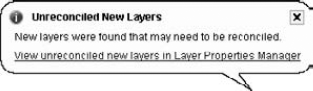
When you open the Layer Properties Manager in this way, you see only unreconciled layers. (AutoCAD activates the Unreconciled New Layers filter for your layers.) These are layers that have been added to the drawing (either consciously or via xrefs) but that you haven't yet reviewed. You can perform one of three actions:
Leave the layer unreconciled.
Reconcile the layer. Right-click the layer in the Layer Properties Manager and choose Reconcile Layer.
Delete the layer.
Note
The layer notification settings are saved with the drawing, so each drawing can have its own settings.
When you create a template (as I explain in Chapter 2), after saving, the Template Options dialog box opens. Here you can decide if you want drawings created from that template to use reconciled or unreconciled layers. If you choose the default option, Save All Layers As Unreconciled, you can add layers without notification until you save the drawing. Saving the drawing creates a baseline, after which the notification starts. If you save layers as reconciled, then any new layers are considered unreconciled and you'll be notified about them according to your settings in the Layer Settings dialog box.
If you receive drawings from clients or colleagues, you might find that their layer system doesn't suit yours. Manually translating one set of layers to another to fit your layer standards could be a tedious job. The LAYTRANS command changes the layers of objects by specifying sets of "from" and "to" layers. For example, you can change all objects on layer1 to the layer objects. Use this feature to maintain layer standards.
Note
The Layer Translation feature is not available in AutoCAD LT.
On the Translate From side of the dialog box, you see the layers in the drawing. (Layers with a white icon to their left are not being used. You can right-click them and choose Purge Layers to purge them from the drawing.) Select layers by clicking them. You can also select multiple layers. You can type a selection filter in the Selection Filter text box to select certain layers.
Note
See the section "Filtering the layer list" in Chapter 11 for more information about filtering layer lists.
To load existing layers, click Load. In the Select Drawing File dialog box, you can choose a drawing, a drawing template, or a drawing standards file. Click Open. The layers from that file now appear in the Translate To list. Select the layer to which you want to translate.
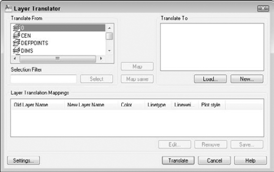
To define a new layer, click New. In the New Layer dialog box, type a name for the new layer and specify its color, linetype, lineweight, and plot style. Click OK.
To specify how layers are translated, map layers in the current drawing (listed in the Translate From list) to the layers to which you want to convert (listed in the Translate To list). Select a layer in the Translate From list, then select a layer in the Translate To list, and then click Map. The mapping appears below in the Layer Translation Mappings list. Finally, you're ready to translate your layers. Click Translate, and AutoCAD takes care of the rest. All objects on the Translate From layers are now on the Translate To layers. The translation process also purges unused layers from the drawing.
Tip
You can select more than one layer from the Translate From list by pressing Ctrl for each additional layer. You can select a contiguous group of layers by clicking the first layer in the group, holding Shift, and selecting the last layer in the group. Then from the Translate To list, select the layer that you want to map that group of layers to, and click Map. You can also quickly map all layers with the same name by choosing Map Same.
After you create your mappings, you can edit, remove, or save them:
To edit a mapping, select it and click Edit. In the Edit Layer dialog box, you can choose a new layer, color, linetype, lineweight, or plot style.
To remove a mapping, select it and click Remove.
To save a mapping, click Save. You can choose to save a mapping as a drawing standards file (
.dws) or as an actual drawing file (.dwg). Type a filename, choose a location, and click Save. (If you don't save your layer mapping, AutoCAD prompts you to do so.)Click Settings to customize the translation process. Here are your options:
The first two options in the Settings dialog box force objects to take on their layer's assigned color and linetype. Check these two settings to enforce consistency in your layer properties.
The Translate Objects in Blocks item determines whether layer mappings are applied to objects within blocks. See Chapter 18 for more about blocks.
Check Write Transaction Log to create a
.logfile in the same folder as the drawing that you're translating (the current drawing). The log file lists the details of the translation and can help you troubleshoot problems later.Check Show Layer Contents When Selected to help you figure out which objects are on which layers. If you check this item and then select a layer translation in the Translate From or Layer Translation Mappings list, only objects on that layer are shown.
After you finish specifying the translation settings, click OK to close the Settings dialog box.
Note
The drawings used in the following exercise on managing CAD standards, ab26-e.dwg and ab26-e.dws, are in the Drawings folder on the DVD.
STEPS: Managing CAD Standards
Open
ab26-e.dwgfrom the DVD.Save the file as
ab26-03.dwgin yourAutoCAD Biblefolder.Open the Layer Properties Manager palette by choosing Home tab
To try out the layer notification feature, click the Evaluate All New Layers option and check the Save check box. Click OK.
In the Layer Properties Manager palette, click the New Layer button. Leave the default properties unchanged.
Save the drawing. The Unreconciled New Layers bubble appears. Click the link in the bubble to open the Layer Properties Manager palette, showing the new layer. Click the Delete Layer button to remove Layer 1.
Choose Home tab

In the Configure Standards dialog box, click the + button. Find and choose
ab26-e.dws, a drawing standards file, on the DVD. Click Open to associateab26-e.dwswithab26-03.dwg.In the same dialog box, click Check Standards to open the Check Standards dialog box.
The first standards problem,
Layer 'AME_FRZ' Name is non-standard, is listed in the Problem box. Click the Next button to ignore this problem.The next problem is
Layer 'CEN' Properties are non-standard. Choose CEN from the Replace With list and click the Fix button.Continue to make the following changes, clicking the Fix button after each one:
LINETYPE       BORDERX2      BORDER
LINETYPE        CENTERX2        CENTER
LINETYPE        HIDDENX2        HIDDEN
LINETYPE        PHANTOM2        PHANTOM
TEXTSTYLE       ZONE            ROMAND
TEXTSTYLE       TECHNIBOLD      ROMANS
The Check Standards - Checking Complete dialog box appears with a summary of the standards check. Click Close.
Open the Linetype Control drop-down list again. The "x2" linetypes have been purged.

On the right side of the Layer Translator dialog box, click Load. From the Files of Type drop-down list, choose Standards (
*.dws). Chooseab26-e.dws, the same standards file that you used previously in this exercise, and click Open.In the Translate From box, click CEN. Hold down the Ctrl key and click HAT.
In the Translate To box, click HID.
Click Map. This will map the layers CEN and HAT to the HID layer.
Click Translate to translate the mappings.
In the Layer Translator – Changes Not Saved dialog box, click Translate Only. All objects on the CEN and HAT layers are now on the HID layer.
Save your drawing.
To access the information for the first time, click the down arrow to the right of the Search text box at the upper-right corner of the application window, and choose Search Settings to open the InfoCenter Settings dialog box. You can set the following:
General. Specify your country and how often you want the Communication Center to check for new content.
Search Locations. Specify which locations you want to include in the results when you enter a question in the search box. I discuss using the Search box in Chapter 3.
Note
In order to configure the Communication Center, you need to install Autodesk CAD Manager Tools. For more information, see Appendix A. You then need to choose Start
Communication Center. This item displays a CAD Manager Channel, a URL of an RSS news feed that a CAD Manager can use to make content available to AutoCAD users. You need to enable the CAD Manager Channel and enter the feed URL in the CAD Manager Control Utility.
Autodesk Channels. If you have enabled information channels in the CAD Manager Control Utility, you can choose which Autodesk channels you want to see here. Available channels include Live Update maintenance patches, subscription announcements (for those users on AutoCAD's subscription program), articles and tips, featured technologies and content, and product support information.
Balloon Notification. Choose if you want to see a balloon pop up to notify you of new content, and for which type of type of content.
RSS Feeds. Use the New and Remove buttons to add and remove RSS feeds, respectively. RSS feeds are files that contain notification of new content, such as for blogs. You need to know the full URL of the RSS feed's file. (The URL of my AutoCAD Tips Newsletter RSS feed is
www.ellenfinkelstein.com/autocad_tips_newsletter.xml.)
Click OK when you're done. After you specify the settings, click the Communication Center button to open the Communication Center window. From this window, you can click any link to access its source on the Internet.
Drawings contain many named objects, such as layers, text styles, dimension styles, and so on. Sometimes you need to rename these objects in order to maintain CAD standards and consistency. To rename objects, type rename
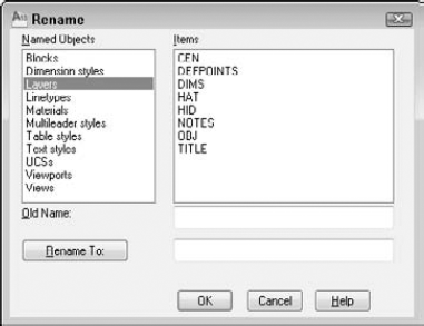
To rename objects, follow these steps:
Choose the type of object that you want to rename from the Named Objects list.
Choose the item that you want to rename from the Items list. This item appears in the Old Name text box.
In the Rename To text box, type the new name for the item.
If you want to change only one item, click OK to close the dialog box.
If you want to change more than one item, click Rename To. The dialog box remains open so that you can make other changes. Click OK after you're finished.
Many AutoCAD users create sets of drawings that need to be delivered to a client. In an architectural setting, a set of drawings includes a cover page, floor plans, elevations, and sections, and may include additional sheets of sections, notes, and so on. In an engineering setting, a set of drawings may include a top view, a side view, and a section, in addition to schedules and other data. Organizing and managing all these drawings can be a huge task. Because the sheets are numbered and reference each other, one change can involve renumbering and rereferencing the entire set of drawings.
Note
The sheet set feature is available in AutoCAD only.
The sheet set feature offers a major rethinking of how you work with drawings. You still create your drawings in much the same way, but then you define sheets — paper space layouts — into sheet sets. You can do the following with sheet sets:
Number them. Each sheet can have a number so that you can easily reorder them. Using fields, you can automate the process of placing the sheet number on each sheet. Changes in the sheet set order automatically change the number on the sheets (after reloading or regenerating the drawing).
Plot and publish them. You can plot or publish the entire sheet set or any selection set of sheets, all at once.
Associate them with a template. You can ensure that every sheet uses the same template, or organize them so that certain sheets use certain templates. By associating a standards file with the template, you can also ensure standards compliance.
Manage, open, and find them. From the Sheet Set Manager, you can easily open or find any of the drawings in the set. You can also delete any sheet.
Transmit and archive them. You can eTransmit the entire sheet set, along with any dependent files. You can also create an archive package for backup purposes.
Facilitate multiple-user access. Although only one drawing can be open at a time, multiple people can have access to the sheet set information.
Create an index sheet. You can create a table for an index sheet that lists all the sheets in the sheet set.
Automate the creation of viewports. You can use named views in model space to create views in viewports on a paper space layout, and specify the scale as you place the viewport.
Automate the completion of text in a titleblock. You can use fields to automatically place text in each titleblock of the sheet set.
Automate labeling and referencing. Using fields, you can automate the process of creating sheet labels and callouts. Labels and callouts contain numbers that are updated when sheets are reordered. Callouts are hyperlinks so that you can immediately go to the view that the callout references.
As you can see, sheet sets are a tool for managing and automating many of the organizational tasks that you need to do every day if you work with groups of drawings.
The drawings that you need to deliver may have one drawing with three layouts, another with one layout, and a third with four layouts. You need to deliver sheets, which are layouts, but they can be hard to manage when some layouts are in one drawing, some in another, and so on.
When you work with sheet sets, you can pull content from resource drawings that have many layouts or a few, but you create new sheets, and each sheet is a drawing. For this reason, the sheet set structure creates new drawings, each with one layout.
You manage sheet sets and their individual sheets in the Sheet Set Manager, as shown in Figure 26.17. The Sheet Set Manager is a palette like the Properties palette. For example, you can auto-hide it in the same way. To open the Sheet Set Manager, choose View tab
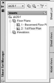
The Sheet Set Manager has three tabs:
Sheet List contains the sheets that you create for the sheet set. You use this tab to manage and organize the sheet set. You can set properties for the sheet set, for subsets (categories), and for individual sheets. You can use this tab to add and remove sheets, and to import a layout from another drawing as a sheet. You can also use it to plot, publish, eTransmit, or archive an entire sheet set or a selection of sheets, to rename and renumber sheets, and to close the sheet set. You can also open any sheet, which is the same as opening the drawing. Figure 26.17 shows the Sheet List tab.
Sheet Views contains a list of paper space views, which are viewports on a layout. A layout can have more than one viewport. You can create view categories, such as elevation and floor plan. You can display the view from this tab. You also use this tab to rename and renumber your views within a layout, as well as to place label blocks that label a view and callout blocks that reference other views. See Figure 26.18 on the left.
Model Views lists the drawings that are the source of your sheets, as well as their model space views, as shown in Figure 26.18 on the right.
Tip
By hovering your cursor over an item in the Sheet Set Manager, you can preview and read details of sheet set layouts on a tooltip. Set preview and detail size preferences by right-clicking near the top of the palettes and choosing Tooltip Style.
Many AutoCAD users who work with multiple drawings create a folder structure to help organize the drawings. Sheet sets work the same way. You should start by creating a folder for your sheet set. If you want, you can create folders for categories. In the architectural example shown in Figures 26.17 and 26.18, the categories are Floor Plans, Elevations, and Sections. These become subsets in your sheet set. Finally, you should create a subfolder for your model space drawings, which are the drawings that you'll use to create the sheet set.
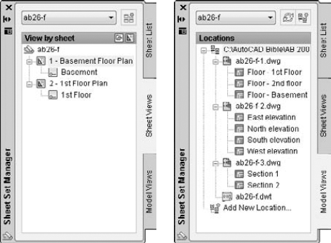
Figure 26.18. On the left, you see the Sheet Views tab, which displays the views on your sheets. On the right, you see the Model Views tab, which contains the source drawings for your sheet set.
If you plan to use existing layouts as sheets, they should ideally have only one layout, especially if more than one person sometimes accesses drawings. Only one sheet in a drawing can be open at a time. Also, before you import existing layouts or create new sheets, you should first prepare your template — as I explain in the "Setting up sheet set references" section — especially if you plan to use the automatic numbering and referencing features of sheet sets.
To create a sheet set, open the Sheet Set Manager and choose New Sheet Set from the drop-down list at the top of the palette. The Create Sheet Set Wizard opens with the Begin pane displayed, as shown in Figure 26.19.
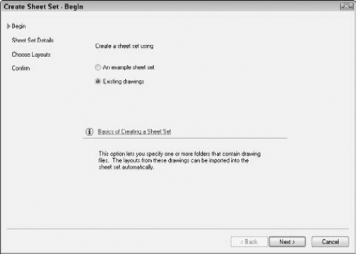
You can choose to use an example sheet set that you've already created or that comes with AutoCAD, in order to use its structure. If you want to work with existing drawings, choose the Existing Drawings option. Then click Next. If you chose to use an example, the next screen allows you to choose the sheet set. Choose one and click Next. The following steps assume that you have chosen the Existing Drawings option.
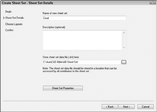
On the Sheet Set Details pane, shown in Figure 26.20, you name the sheet set, add an optional description, and specify the location of the file that contains the data for the sheet set; the default location is automatically entered for you but you can change it. Sheet set files have a .dst filename extension, and you can store them in the same folder as the sheets. Click the Ellipsis button to open the Browse for Sheet Set Folder dialog box. There you can navigate to a folder or create a new folder by clicking the Create New Folder button. Then click Open to return to the wizard.
You can click the Sheet Set Properties button at this point to specify various settings, but you have access to these properties from the Sheet Set Manager, so you can skip the properties at this stage. Click Next.
If you chose the Existing Drawings option on the first pane, you now see the Choose Layouts pane of the wizard. Click Browse to add existing drawings that have layouts that you want to include in the sheet set. If you've created only model space drawings and want to create new sheetsinstead of including layouts from these drawings, you can skip this pane and click Next. However, if you have layouts that you've already set up, browse to a folder and click OK. You can continue to click Browse and add more folders if you want. You can then uncheck any folders that you don't want to include.
Click Import Options to open the Import Options dialog box. Here you can decide whether you want the sheet name to include the drawing name before the layout name. You can also choose to use your folder structure to create subsets. For example, if you have folders named Floor Plans, Elevations, and Sections, you could automatically create the subsets that you see in Figure 26.17. Click OK to close the Import Options dialog box and return to the wizard.
Click Next to display the Confirm pane of the wizard. This pane summarizes the choices that you made in the wizard. If you want to change something, click Back. Otherwise, click Finish. You can change everything later except for the sheet set filename and location. Clicking Finish creates the DST file in the location that you chose.
The Sheet Set Manager now displays your new sheet set. If you didn't import any layouts, all you see is the Sheet List tab with the name of the sheet set. If you did import layouts, they're listed. You're now ready to set the properties of your sheet set.
Before you go any farther, you need to set the properties of your sheet set. These properties ensure that every aspect of the sheet set works the way that you want it to. You can separately set properties for the sheet set as a whole, for subsets, and for individual sheets. To set sheet set properties, right-click the name of the sheet set at the top of the Sheet List tab of the Sheet Set Manager, and choose Properties to open the Sheet Set Properties dialog box, as shown in Figure 26.21.
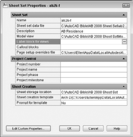
The Sheet Set Properties dialog box always contains the sheet set name and sheet set data file (DST) location. Complete the rest of the properties as follows:
Description. Click this item and type a new description, or edit an existing description.
Model view. Click this item to display the Ellipsis button. Click the button and then click Add to browse to a folder containing drawings that you want to use for your sheets. Click Open and then click OK to return to the Sheet Properties dialog box. You can add more than one location. These drawings contain model space content that you want to place on layouts for your sheets. For easy organization, create a
Model viewsfolder inside the sheet set folder, and place your drawings there. The folders that you enter here appear on the Model Views tab of the Sheet Set Manager.Label block for views. A label block labels a view and usually includes the view name, view number, and scale. To choose a label block, click this item and click the Ellipsis button. In the Select Block dialog box, click the Ellipsis button to choose a drawing that contains the block that you want. (If your block is in your template, choose AutoCAD Drawing Template [
*.dwt] from the Files of Type drop-down list.) Click Open. If the drawing contains only that block (in other words, if the drawing is the block that you want to use), choose the Select the Drawing File as a Block option. If the drawing contains several blocks, use the Choose Blocks in the Drawing File option. You then see a list of the blocks in the drawing. Choose the block that you want (you can choose only one label block) and click OK. If you want to use the automatic numbering and referencing feature of sheet sets, you need to set up this block, as I explain later in this chapter in the "Setting up sheet set references" section. If you want different blocks for different subsets, or if you don't use a label block, leave this item blank.Callout blocks. Callout blocks point to other drawings. For example, on a floor plan, a callout block marks the location of a section view that is on another sheet. To choose a callout block, click this item and click the Ellipsis button. In the List of Blocks dialog box, click the Add button. Then in the Select Block dialog box, click the Ellipsis button to choose a drawing from the Select Drawing dialog box that contains the blocks that you want. (For a template, choose AutoCAD Drawing Template [
*.dwt] from the Files of Type drop-down list.) Click Open. If the drawing contains only that block (in other words, if the drawing is the block that you want to use), choose the Select the Drawing File as a Block option. If the drawing contains several blocks, use the Choose Blocks in the Drawing File option. You then see a list of the blocks in the drawing. You can choose multiple callout blocks, because many drawings contain variations of this type of block. Click OK twice to return to the Sheet Set Properties dialog box. If you want to use the automatic numbering and referencing feature of sheet sets, you need to set up this block, as I explain later in this chapter in the "Setting up sheet set references" section. If you want different blocks for different subsets, or if you don't use callout blocks, leave this item blank.Page setup overrides file. You may want to override page setups (which I explain in Chapter 17) if you imported layouts with varying setups. You may want to plot the entire sheet set with one page setup, rather than use page setups that came with individual layouts. You save these page setups in a template. Click this item, click the Ellipsis button that appears, choose a template, and click Open. You can create this template later and then go back and specify it.
Project control. This feature provides a location to enter project information, including a project number, name, phase, and milestone. This information then appears in the Details section of the Sheet List tab of the Sheet Set Manager.
Sheet storage location. This folder defines where sheets are stored. If you didn't specify this location when you created the sheet set, click this item, click the Ellipsis button, choose a folder, and click Open. Note that if the sheet set already contains sheets, changing this location doesn't move existing sheets; it only affects the location of new sheets that you create.
Sheet creation template. Click this item and then the Ellipsis button. Then click the Ellipsis button in the Select Layout as Sheet Template dialog box. Choose a template (or a drawing or standards file) and click Open. You can then click a layout in the template. Click OK.
Prompt for template. If you want your sheets to automatically use the template, this item should be set to No. If you sometimes vary your templates, set this item to Yes so that you can choose a different template when you want.
You can create custom properties. You create custom properties to automatically insert text in your titleblock, using AutoCAD's field feature. After you create these properties, they become fields that you can insert. (See "Inserting Fields" in Chapter 13 for a discussion of fields.) A custom property can apply to a sheet set or an individual sheet. Common sheet set custom properties are client name, project name, or project address. A typical sheet set custom property would be the drawer's or proofer's initials, if more than one person works on the sheets in the sheet set.
To add custom properties, click the Edit Custom Properties button. In the Custom Properties dialog box, click Add. Then enter a name and a default value, and choose whether the property is for a sheet or a sheet set. (Adding a default value helps you test the fields when you set up your titleblock.) Click OK. Continue to click Add and define custom properties. When you're done, click OK to return to the Sheet Set Properties dialog box.
Warning
After you create custom properties, you can't change their name. To do so, you would need to delete and re-create the properties.
When you finish setting your sheet set properties, click OK to return to the Sheet Set Manager and your drawing.
Subsets are categories that you can use to help you organize your sheets. They may or may not have corresponding folders where you keep sheets. To create a subset, right-click the sheet set name and choose New Subset. In the Subset Properties dialog box, name the subset and specify the location of the sheet drawings files for that subset as well as the template. The default location for both is the same as for the entire sheet set.
Note
In the Subset Properties dialog box, you can choose to include the subset when publishing the sheet set or to not publish the subset. See the "Plotting and publishing" section later in this chapter for more information.
After you've created a subset, you can change its properties by right-clicking the subset and choosing Properties from the shortcut menu.
When you create your sheets, you can set sheet properties in the same way, by right-clicking and choosing Properties.
One of the more exciting features of sheet sets is the ability to automate the completion of text in the titleblock, as well as the numbering of sheets, titleblocks, and callout blocks. However, this feature is also fairly complex. You can omit this feature and still get significant benefits from sheet sets, such as the ability to plot the entire sheet set all at once and automate the creation of viewports. In this section, I explain how to configure the label and callout blocks so that the automation features work properly.
The secret of this feature is the use of fields, which I cover in Chapter 13 (in the "Inserting Fields" section). You can use the fields in two ways:
Place the fields in Mtext, which you insert in your titleblock, label block, and callout blocks.
Place the fields using attributes that you associate with these blocks. I cover attributes and blocks in Chapter 18.
The advantage of using attributes is that text cannot easily be changed. If you're a CAD Manager and want to reduce errors, you might choose to use attributes. Of course, if you already use attributes, you might find it simpler to continue to use them. On the other hand, you might want the increased flexibility and simplicity of Mtext, especially if you don't currently use attributes. One of the reasons for using attributes is to place text; using Mtext with fields works just as well to specify text placement.
There are many ways of creating a titleblock. In this section, I assume that you have a template that contains a titleblock that you've inserted on a layout. This template would also contain your text styles, table styles, dimension styles, layers, and so on.
Tip
To configure your template, don't open it directly. Instead, create a new sheet in your sheet set. This sheet will automatically be based on the template that you specified in the Sheet Set Properties dialog box. When you finish configuring this sheet, you will save it as a template. To create the sheet, right-click the sheet set name and choose New Sheet. Give the sheet a name that indicates that it will become a template, such as WillBeTemplate. This technique allows you to test your fields as you work, because the sheet is part of the sheet set (unlike a template that you open directly). Thanks to Heidi Hewett of Autodesk for this tip.
At this point, you should look at your titleblock and determine any custom properties that you need, as I explained in the previous section. You should set up these properties before you go on.
Create a new sheet on the Sheet List tab of the Sheet Set Manager. Double-click the sheet to open it. You should now see your template with its titleblock. If the titleblock text is part of a block, whether Mtext or attributes, explode the titleblock.
Tip
Don't try to edit attributes or blocks by using the Block Attribute Manager (BATTMAN command) or the REFEDIT command, because the existing block's text will not be updated with the new field values. Instead, explode the block, change the text to fields, and redefine the block. Thanks to Heidi Hewett of Autodesk for this tip.
Double-click the Mtext or attribute text to open the In-Place Text Editor or the Edit Attribute Definition dialog box. To replace the text with a field, follow these steps:
Select the text.
Right-click and choose Insert Field to open the Field dialog box.
Choose one of the following fields:
CurrentSheetCategory. The view category for the current sheet.
CurrentSheetCustom. Custom properties that apply to individual sheets.
CurrentSheetDescription. The description that you entered for a sheet.
CurrentSheetIssuePurpose. The purpose property for a sheet.
CurrentSheetNumber. The sheet number.
CurrentSheetNumberandTitle. The sheet number and name.
CurrentSheetRevisionDate. The revision date for the current sheet.
CurrentSheetRevisionNumber. The revision number for the current sheet.
CurrentSheetSet. The name of the sheet set.
CurrentSheetSetCustom. Custom properties that apply to the sheet set.
CurrentSheetSetDescription. The sheet set description that you specified.
CurrentSheetSetProjectMilestone. The milestone value from the Project Control section of the Sheet Set Properties dialog box.
CurrentSheetSetProjectName. The project name from the Project Control section of the Sheet Set Properties dialog box.
CurrentSheetSetProjectNumber. The project number from the Project Control section of the Sheet Set Properties dialog box.
CurrentSheetSetProjectPhase. The project phase value from the Project Control section of the Sheet Set Properties dialog box.
CurrentSheetSetSubSet. The name of the subset that the current sheet is in.
CurrentSheetTitle. The name of the sheet.
Sheet Set. The name of the sheet set.
CreateDate. Places the current date. (Unlike the Date field, this field doesn't update each time you open or regenerate the drawing.)
You may find other fields that are useful for your titleblock.
Choose a format from the Format list.
If you chose one of the custom fields, choose the specific field from the Custom Property Name drop-down list.
Note
You should immediately see the value of your field, either in your drawing or in the Edit Attribute Definition dialog box.
Click OK. Repeat Steps 1 through 5 to continue to add fields for the entire titleblock in this way.
Choose Application Button
You can now delete the sheet from the sheet set. Deleting a sheet doesn't delete the drawing. Right-click the sheet and choose Remove Sheet. Click OK to confirm. The drawing is still open.
The template is now open on your screen. If you exploded the titleblock, you need to redefine the block. If you're using attributes for your text, you need to include the text as attribute definitions.
Select all the objects in your titleblock. Choose Insert tab
You can now immediately define label and callout blocks directly in the template. If you don't need these blocks, skip the next section and close the template.
Label blocks can automatically display the sheet number, sheet name, and scale. Callout blocks can automatically display the view number (often called the detail number), as well as the sheet number. In addition, callout blocks can contain a hyperlink to the view that they reference so that users can immediately display that view. You can see an example of label and callout blocks in Figure 26.23.
To set up your label and callout blocks, the simplest solution is probably to work directly in the template. When you're done, you'll delete the inserted blocks to keep only their definitions. If you want to store these blocks in a separate drawing, open the drawing. Follow these steps:
Choose Insert tab
Explode the block.
Double-click the text that contains the view number. (This is often called the detail number and will number a floating viewport containing one view of the drawing.) The In-Place Text Editor opens (the Edit Attribute Definition dialog box opens if the text is an attribute).
Select the text. (In the Edit Attribute Definition dialog box, select the text in the Default text box.) Right-click and choose Insert
From the Field Names list, choose SheetSetPlaceholder. From the Placeholder Type list, choose View Number.
Repeat Steps 3 through 5 for the view name and the view scale, using the ViewTitle and the ViewportScale types of the SheetSetPlaceholder field, respectively.
To redefine the block, select all the objects, choose Insert tab
Tip
You can use the Block Editor to edit the block. Then you don't have to explode or redefine the block.
Note
If your text is composed of attributes, choose Insert tab
If you didn't choose the Delete option in the Block Definition dialog box, delete the block. The block definition stays in the template's database and will be available to any drawing that you base on that template.
Repeat Steps 1 through 8 for your callout blocks. For these blocks, you use the SheetSetPlaceholder field with the ViewNumber and SheetNumber field types. However, for callout blocks, be sure to check the Associate Hyperlink check box in the Field dialog box, so that the callout bubble will link to the view (detail) that it references.
Save the template and close it.
You're now ready to use your sheet set.
After you've configured your sheet set properties, you're ready to use your sheet set. The first step is to specify the value of any custom properties that you have defined so that they'll appear in your titleblock text property. On the Sheet List tab, right-click the sheet set name and choose Properties. Click Edit Custom Properties and set the values that you want.
You can now add sheets. Each sheet will be a separate drawing with one layout tab. To add a sheet, follow these steps:
Display the Sheet List tab of the Sheet Set Manager.
Right-click the sheet set name and choose New Sheet.
In the New Sheet dialog box, give the sheet a number and a name.
The name of the drawing is automatically completed, using both the number and the name of the sheet.
Tip
You can delete the number in front of the sheet name. Otherwise, if you change the order of your sheets, the drawing filename won't change, and your filenames get out of sync.
Click OK. The new sheet appears on the Sheet List tab.
If you created sheet properties, right-click the sheet name and choose Properties. Change the values of any custom properties that are specific for that sheet.
Tip
You can import a layout as a sheet by displaying the layout and dragging from the layout tab to the Sheet List tab of the Sheet Set Manager.
Tip
You can quickly preview and easily switch between all open drawings and layouts by choosing Quick View Drawings from the status bar. To make the thumbnails larger or smaller, hold down the Ctrl key while using your mouse wheel's scroll feature.
To organize your sheets, you can create subsets. A subset is just an organizational tool, although you can create a folder structure that matches your subsets. You can also assign different templates to sheets in different subsets. To add a subset, right-click the sheet set name and choose New Subset. You can also right-click an existing subset and choose New Subset to create a nested subset. In the Subset Properties dialog box, name the subset. You can also assign a template and folder location. Click OK.
On the Sheet List tab, you can also do the following with sheets:
Move sheets. You can place sheets in a different order by dragging them. You can drag multiple sheets to a new location or subset.
Remove sheets. Right-click any sheet and choose Remove Sheet. You can also select multiple sheets to remove all the selected sheets. Click OK to confirm.
Change a sheet's name and number. Right-click a sheet and choose Rename & Renumber. Type a new number, a new name, or both, and click OK. Note that renumbering a sheet doesn't change its order on the Sheet List. Two sheets can have the same number. You can use any numbering system that you want.
Note
When changing a sheet's name, you have an option to also change the name of the associated drawing file to match the new sheet name.
Change sheet properties. Right-click a sheet and choose Properties. Make any changes that you want in the Sheet Properties dialog box and click OK.
Import a sheet. You can create a sheet by importing a layout tab of an existing drawing. On the Sheet List tab, right-click the sheet set name and choose Import Layout as Sheet. In the Import Layouts as Sheets dialog box, click the Browse for Drawings button. Navigate to a drawing and click Open. Then choose the layouts in that drawing that you want to import. Click the Import Checked button.
Note
To import a layout as a sheet, you must have displayed a layout tab in that drawing; otherwise, you get a message that the drawing does not contain any initialized layouts. To remedy the situation, open the drawing, click the layout tab, and save the drawing. Then close the drawing. You can now import the layout into your sheet set.
Note
The drawings and files used in the following exercise on creating and configuring a sheet set, ab26-f-1.dwg, ab26-f-2.dwg, ab26-f-3.dwg, and ab26-f.dwt, are in the Drawings folder on the DVD.
STEPS: Creating and Configuring a Sheet Set
Note: This is a long exercise. You should leave yourself 45 to 60 minutes to complete it.
Open Windows Explorer. (Right-click the Windows Start button and choose Explore.) In the folder pane, locate and click the
AutoCAD Biblefolder that you created for the exercises in this book. From the menu, choose FileClick the new
AB 2010 Sheet Setfolder and again create a new folder. Name the new folderModel View Drawings.Copy
ab26-f-1.dwg, ab26-f-2.dwg, ab26-f-3.dwg, andab26-f.dwt(a template file) from the DVD of this book to theModel View Drawingsfolder.Open a new drawing, based on any template. (You need a drawing open to create a new sheet set, but not to open an existing one.)
Choose View tab
On the Begin pane, choose Existing Drawings and click Next.
In the Name of New Sheet Set text box, type ab26-f. In the Description text box, type AB Residence, size A. (You wouldn't normally use size A sheets for architectural drawings, but using this size enables you to print the sheets on your printer if you don't have a plotter available.) In the Store Sheet Set Data File (
.dst) Here box, click the Ellipsis button and navigate to theAutoCAD BibleAB 2010 Sheet Setfolder that you created in Step 1. Click Open and then click Next.On the Choose Layouts pane, click Next. You're going to create the sheets from scratch rather than import them. (You will use the existing drawings for the model view, but you won't use them as the sheets themselves.)
On the Confirm pane, read the information. If it's correct, click Finish. (Otherwise, click Back and make any corrections that you want.)
Click the Sheet List tab of the Sheet Set Manager if it isn't already on top. You should see your sheet set listed. Right-click the sheet set name and choose Properties from the shortcut menu.
In the Sheet Set Properties dialog box, set the following items:
Model view. Click the Ellipsis button. Click Add. Navigate to the
AutoCAD BibleAB 2010 Sheet SetModel View Drawingsfolder that you created in Step 2. Click Open. Click OK to return to the Sheet Set Properties dialog box.Label block for views. Click the Ellipsis button. In the Select Block dialog box, click the Ellipsis button again. If necessary, choose AutoCAD Drawing Template (
*.dwt) from the Files of Type drop-down list. Navigate to theAutoCAD BibleAB 2010 Sheet SetModel View Drawingsfolder and chooseab26-f.dwt. Click Open. Choose the Choose Blocks in the Drawing File option. Choose theview labelblock. Click OK.Callout blocks. Click the Ellipsis button. In the List of Blocks dialog box, click Add. In the Select Block dialog box, click the Ellipsis button. If necessary, choose AutoCAD Drawing Template (
*.dwt) from the Files of Type drop-down list. Navigate to theAutoCAD BibleAB 2010 Sheet SetModel View Drawingsfolder and chooseab26-f.dwt. Click Open. Choose the Choose Blocks in the Drawing File option. Choose theCallout button-left arrowblock. Click OK twice.Sheet creation template. Click the Ellipsis button. In the Select Layout as Sheet Template dialog box, click the Ellipsis button. If necessary, choose AutoCAD Drawing Template (
*.dwt) from the Files of Type drop-down list. Navigate to theAutoCAD BibleAB 2010 Sheet SetModel View Drawingsfolder and chooseab26-f.dwt. Click Open. (If the template contained more than one layout, you would choose the layout of the template that you want to use.) Click OK.Prompt for template. Choose No from the drop-down list if this value is set to Yes.
Click Edit Custom Properties. Click Add. In the Add Custom Property dialog box, add the following custom properties:
Customer Name, with a value of CustomerName, sheet set
Customer Address 1, with a value of CustomerAddress1, sheet set
Customer Address 2, with a value of CustomerAddress2, sheet set
Drawn By, with a value of DB, sheet
Checked By, with a value of CB, sheet
Click OK to close the Custom Properties dialog box. Click OK again to close the Sheet Set Properties dialog box and return to your drawing.
Right-click the sheet set name and choose New Subset. In the Subset Properties dialog box, type Floor Plans in the Subset Name field and click OK. Repeat this process to add subsets for Elevations and Sections.
To configure the titleblock text, right-click the sheet set name and choose New Sheet. Because you'll later save this sheet as a template and then delete it, number it XX and name it WILL BE TEMPLATE. (This technique helps you to confirm your fields.) Delete the XX from the front of the filename and click OK.
Double-click the new sheet to open it. You should see the template's titleblock.
Double-click the text
CustomerNameto open the In-Place Text Editor. Select the text, right-click, and choose Insert Field. Choose SheetSet from the Field Category drop-down list to filter the fields that you see on the Field Names list. Choose CurrentSheetSetCustom (check the field name carefully, because there are many similar fields), set the format to Title case, and choose Customer Name from the Custom Property Name drop-down list. Click OK. You now see the text surrounded by the gray field box. Click outside of the In-Place Text Editor to close it. In the same way, set the following other fields:CustomerAddress1. CurrentSheetSetCustom, Title case, Customer Address 1
CustomerAddress2. CurrentSheetSetCustom, Title case, Customer Address 2
DB. (Drawn By) CurrentSheetCustom, Uppercase, Drawn By
CB. (Checked By) CurrentSheetCustom, Uppercase, Checked By
P-01. CurrentSheetNumber, Uppercase
You can now see the values of all the fields in the titleblock.
The Layout tab takes on the name of the sheet, which is WILL BE TEMPLATE. If your drawing window displays the Layout tab, double-click the Layout tab to rename it. If your drawing window doesn't display the Layout tab (the default), first right-click the layout's button on the status bar and click Display Layout and Model Tabs. In the Sheet Set - Rename Layout dialog box, click Rename Layout Only. Name the Layout tab Titleblock and press Enter.
Choose Application Button
You no longer need the WILL BE TEMPLATE sheet. Right-click the sheet and choose Remove Sheet. Click OK to confirm. (Removing the sheet does not remove the drawing or templates.)
The template is still open. Make sure that the current layer is 0.
To configure the label and callout blocks, choose Insert tab
In the same way, insert the
callout bubble-left arrowblock.Select the
view labelblock and choose Insert tabDouble-click the
V#text inside the circle. The Edit Attribute Definition dialog box opens. Select the text in the Default text box. Right-click in the Default text box and choose Insert Field. In the Field dialog box, choose SheetSetPlaceholder as the Field Name and View Number as the Placeholder Type. (If you use view numbers that include letters, choose Uppercase as the Format.) Click OK twice to return to the Block Editor.Note
You don't see the gray field box yet, because you haven't yet inserted the attribute as part of a block.
Use the same procedure to add SheetSetPlaceholder fields for VIEWNAME (use the ViewTitle type and Title case format) and SCALE (use the ViewportScale type and choose the format that you want). Press Enter to end the DDEDIT command.
Select the attributes. Display the Properties palette and change the Preset item's value to Yes.
Click Save Block in the Open/Save panel on the Block Editor tab and click Close Block Editor in the Close panel to return to your drawing.
Repeat Steps 23 through 27 for the
callout bubble-left arrowblock. For the top text, use the ViewNumber placeholder type. For the bottom text, use the SheetNumber placeholder type. This time, be sure to check the Associate Hyperlink check box in the Field dialog box.Delete both blocks. Then save and close the template.
Before you create new sheets, specify the values of the sheet set level custom properties. Right-click the sheet set name on the Sheet List tab of the Sheet Set Manager and choose Properties. The Sheet Set Custom Properties section lists the sheet set properties that you created earlier. (You might have to scroll down in the Sheet Set Properties dialog box to see them.) For Customer Name, type AB Residence. For Customer Address 1, enter any address. For Customer Address 2, enter any city, state, and ZIP or postal code. Click OK to return to your drawing.
On the Sheet List tab of the Sheet Set Manager, right-click the Floor Plans subset and choose New Sheet. Number the new sheet 1 and name it Basement Floor Plan. Delete the number 1 from the filename and click OK. In the same way, create a sheet 2 named 1st Floor Plan, and a sheet 3 named 2nd Floor Plan.
In the same way, add four new sheets to the Elevations subset:
4: East Elevation
5: North Elevation
6: West Elevation
7: South Elevation
In the same way, add two new sheets to a new Sections subset: a sheet 8 called Internal Sections and a sheet 9 called External Sections.
Right-click each sheet that you've created and choose Properties. Change the values for the DB and CB sheet properties to any initials.
Leave AutoCAD and the Sheet Set Manager open for the next exercise.
When your sheet set is configured and you've created your sheets, you're ready to use your sheet set. You can create viewports on your sheets, insert callout blocks, plot or publish sheets, archive and eTransmit sheets, and create a table that lists all the sheets.
A major feature of a sheet set is the ability to create viewports on your sheets. You do this by creating named views in model space in your resource drawings. Then you place the view onto a layout to create a viewport. (For information on named views, see the section "Creating a Layout in Paper Space" in Chapter 8. For coverage of viewports, see the section "Creating a Layout in Paper Space" in Chapter 17.) When you place the view, you can specify the scale that you need.
If you don't already have the named view that you need, click the Model Views tab and double-click the drawing containing the content that you need. This opens the drawing. (If necessary, click the plus sign next to the resource location to display the available drawings.) Click the Model button on the status bar (or the Model tab if it's displayed), define the named view, and then save and close the drawing.
The Model Views tab now lists the named view under the drawing. (Again, you may have to click the plus sign next to the drawing to display the view.)
To create a viewport based on a named view, follow these steps:
Click the Sheet List tab. Double-click the sheet on which you want to place a viewport, to open the drawing with the layout displayed.
Click the Model Views tab.
Right-click the named view that you want to use, and choose Place on Sheet.
Move the cursor onto the drawing area. The command line displays the
Specify insertion point:prompt, and you can see the view on the layout. AutoCAD calculates a standard scale, based on the size of the layout and the size of the view.To change the scale, right-click in the drawing area. A list of scales appears. Choose the scale that you want.
Click to specify the insertion point that you want, and place the viewport. If you've specified a label block, the block automatically appears with its insertion point at the lower-left corner of the view.
Use this procedure to place viewports on all your sheets. Your views now appear on the Sheet Views tab. If you want to place callout or label blocks that use the ViewNumber field, you need to number these views. Right-click a view on the Sheet Views tab and choose Rename & Renumber. Enter a number and a name and click OK. To see the result in an existing field, regenerate the drawing to update the fields.
If you've set up callout blocks, as I describe in the "Configuring label and callout blocks" section earlier in this chapter, now is the time to place them. A callout block references another sheet that contains a detail or a different view. Follow these steps:
On the Sheet List tab of the Sheet Set Manager, double-click the sheet on which you want to place the callout block, to open the layout.
Click the Sheet Views tab, which contains all the model views that you have on your layouts, and right-click the view that you want to reference. Choose Place Callout Block and choose the block. (If you see a Select Blocks submenu item, choose it, choose the block that you want, and click OK to select the block that you want to use. This makes the block available on the menu. Then right-click the view again, choose Place Callout Block, and choose the block.)
At the prompt, pick an insertion point to place the block. The block should display the correct view (detail) and sheet number.
Automation of plotting and publishing is one of the advantages of sheet sets. You can plot or publish an entire sheet set or just part of it, directly from the Sheet Set Manager.
To publish the sheet set, click the sheet set name and choose Publish to DWF. If you plan to publish to DWF format, choose Sheet Set Publish Options from the Publish drop-down list. The Sheet Set Publish Options dialog box opens, where you can specify options for publishing to DWF. For example, you can decide whether you want to publish to single-sheet or multi-sheet DWF format. You can also specify a password and decide how much data you want to make available. For more information about the PUBLISH command and the DWF format, see Chapter 28.
Note
The PUBLISHCOLLATE system variable determines whether a sheet set is published as a single plotting job or as separate jobs for each sheet. The default value, 1, publishes the sheets as a single job. However, to publish sheets as a single job, all sheets must be the same size, and you need to choose the Publish Using Page Setup Override option from the Publish drop-down list on the Sheet List tab of the Sheet Set Manager. Change the value to 0 if you might need to have other plotting jobs interrupt the sheet set. You can also publish the sheet set in reverse order; choose Publish in Reverse Order from the Publish drop-down list. On the same menu, you have options to add a plot stamp, manage plot setups, and open the PUBLISH dialog box.
To plot or publish a subset or sheet, right-click the subset or sheet and use the options on the shortcut menu.
Note
You can include or exclude subsets and sheets when publishing the rest of the set by using the Include for Publish setting. Right-click the sheet set name and choose Publish
You can override the Include for Publish settings for subsets. Right-click the subset name and choose Publish
Archive your sheet sets to save them in ZIP format (by default). You can use the ZIP file for transmittal or backup purposes. (For more information about the archiving process, see the discussion on eTransmitting drawings in Chapter 28.) To archive a sheet set, follow these steps:
Right-click the sheet set name and choose Archive.
In the Archive a Sheet Set dialog box, you can add notes that will go in the archive report, use the tabs to review the files that will be included, view the archive report, and modify current archive settings. Then click OK.
Choose a location for the archive file and click Save.
You create a transmittal when you want to e-mail your sheet set along with all necessary dependent drawings and files. I cover eTransmitting drawings in Chapter 28. To eTransmit a sheet set, follow these steps:
Right-click the sheet set name and choose eTransmit.
In the Create Transmittal dialog box, you can add notes, use the tabs to review the files that will be included, view the transmittal report, and choose a transmittal setup that you've saved. Click OK.
Choose a location for the file and click Save.
A sheet set often has an index sheet that contains a table of contents. Using AutoCAD's table feature, you can automatically generate a table that lists all the sheets in the sheet set or just a subset. To create a table listing the sheets, follow these steps:
Create a new sheet. You can number it sheet 1 or sheet 0.
Double-click the sheet to open its drawing.
Right-click the sheet set name and choose Insert Sheet Set Table to open the Sheet List Table dialog box, as shown in Figure 26.22.
From the Table Style Name drop-down list, choose any table style that you've saved in your template. You can click the Ellipsis button to open the Table Style dialog box and define a table style.
Check the Show Subheader check box if you want to show your sheets divided by subsets.
In the Title Text text box, enter a name to appear as the title of the table. You may want to use the name of the sheet set here, rather than the default text.
In the Column Settings section, specify what data you want to show and how you want to title each column. On the left, you can choose the data from the drop-down lists. On the right, you can change the text. For example, for the Sheet Title item, you may want the title to appear as "Sheet Name." Click Add to add a new column, or click Remove to remove a column. You can also change the order of the columns.
On the Subsets and Sheet tab, check the sheets that you want to include in the table. By default, all the sheets in the set should be included. Uncheck any sheets that you don't want to appear in the table.
Note
To make sure that the table automatically picks up changes to the sheet set, you must check the sheet set name and the subset names. AutoCAD does not update changes to unchecked sheets or subsets.
Click OK.
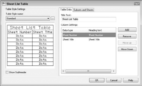
If you make any changes in your sheet set, such as adding or renumbering sheets, you should update the table. Select the table by clicking on any outside border, right-click, and choose Update Sheet List Table.
Note
The drawings and files used in the following exercise on using a sheet set, ab26-f-1.dwg, ab26-f-2.dwg, and ab26-f-3.dwg, are in the Drawings folder on the DVD. The ab26-f.dwt file is in the Results folder. (It's called ab26-f.dwt after exercise.dwt because it contains the results of the previous exercise. Ideally, you should do the previous exercise and use the template that you saved in that exercise.)
STEPS: Using a Sheet Set
You should do the previous exercise before doing this exercise to set up and configure your sheet set and the blocks. If the Sheet Set Manager is not open, choose View tab
Click the Model Views tab of the Sheet Set Manager. Click the plus sign next to the folder name at the top to display the list of the three drawings in the
Model View Drawingsfolder. Click the plus sign next to each drawing to display their model space named views.Click the Sheet List tab. Double-click
1 - Basement Floor Plan. You see the titleblock displayed with all the titleblock fields completed.Change the current layer to
Viewport.Click the Model Views tab again. Expand the ab26-f-1.dwg item in the Sheet Set Manager, right-click
Floor - Basementand choose Place on Sheet. Move the cursor onto the drawing area. (You may want to auto-hide the Sheet Set Manager at this point.) Right-click and choose 1/16″=1'. Place the viewport all the way to the left of the layout. (The view doesn't fit perfectly, but that's okay for this exercise.) The result should look like Figure 26.23, except without the callout block. (If you want, continue to place the floor-plan views on the floor-plan sheets, matching the first- and second-floor views to the sheets. You can also do the same for the four elevation views.)On the Sheet List tab, double-click the External Sections sheet to open it. Make
Viewportthe current layer. Click the Model Views tab. Expand the ab26-f-3.dwg item in the Sheet Set Manager, right-click theSection 2view, and choose Place on Sheet. In the drawing area, right-click and choose 1/16″=1' and pick a point for the view.Click the Sheet Views tab to see the views that you've placed. To number these views, expand each sheet, right-click each view and choose Rename & Renumber. Because you're placing only one view on a sheet, number each view 1 and click OK.
To place a callout bubble on the basement floor plan that references the Exterior Section sheet, click the Quick View Drawings button on the status bar, and choose that drawing from the thumbnails that appear. Click the Sheet Views tab. This tab now lists the views that you just placed. Right-click the
Section 2view (the one that you're pointing to) and choose Place Callout Blocks

Note
If you have any difficulty plotting/printing, you may need to change the page setup to point to your plotter or printer.
To create a table that lists all the sheets, first create a new sheet. On the Sheet List tab, right-click the sheet set name and choose New Sheet. Number it 0 and name it Index Sheet. Delete the 0 from the filename and click OK.
Double-click the new sheet's name to open it.
Right-click the sheet set name and choose Insert Sheet List Table. From the Table Style Name drop-down list, choose Sheet Set List. (This table style was saved with the template.) The Show Subheader check box should be checked. In the Title Text box, type AB26-f Sheets. For the column settings, set up the following columns. If necessary, click Add to add a column.
Sheet     NumberSheet No.
Sheet Title            Sheet Name
Drawing Author         By
Click OK to return to your drawing. Pick an insertion point for the table.
Save and close any open drawings.
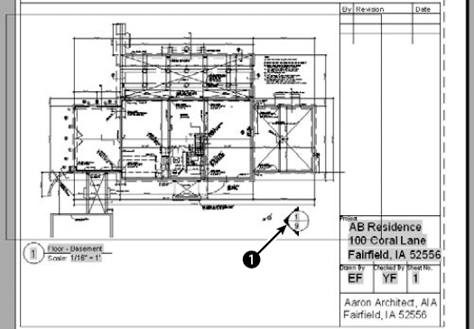
Some offices keep track of thousands of drawings. You must not only track your drawings' names and other properties, but also make sure that you don't lose them! Archiving and finding drawings are important procedures in any CAD environment.
You should use the Autosave feature to regularly save a backup of the drawing to the hard drive. The default time is set to 10 minutes, but automatic backups can still be useful. Choose Application Button
The Autosave time counts from the most recent time you saved your drawing. Therefore, if you manually save more often than every 10 minutes, the feature doesn't create an Autosave file.
Backing up to the hard drive doesn't provide sufficient security. Hard drives can fail. Every time you exit AutoCAD or AutoCAD LT, you should back up every drawing that you worked on to some type of external storage medium. Backing up drawings for storage is called archiving.
Note
On the DVD, I include an AutoLISP program, save2d.lsp, which backs up to the d: drive without leaving your drawing. (You can change it to back up to any drive.) This enables you to back up while working on a drawing. See the SoftwareChapter 01 folder of the DVD. This program works with AutoCAD only.
You'll probably want to invest in one of the many types of removable backup systems. These come in six main types:
Tape drives (internal or external) are cheap and good for entire hard-drive backups.
Disk cartridge drives offer the convenience of a floppy disk but with more capacity.
Read/write DVD-ROM or DVD drives enable you to write to a DVD-ROM or DVD.
Flash drives are easy to use, and you can take them home with you because they're so small.
External hard drives can back up your entire hard drive, and you can take them with you if you travel or need to take them off-site.
Optical drives have the longest life (at least 30 years) and resist accidental erasure.
If your drawings are really important to you, back them up twice and store one backup set off-site. This way, if some disaster strikes your office, you haven't lost everything. Remote backup services provide this type of archiving for you, and you can access your files through the Internet.
The secret to backing up is to create a schedule and then stick to it. For example, you may do a complete hard-drive backup once a week, and do drawing backups at the end of each day. Many software backup programs exist that let you choose what you want to back up and reduce the process to the click of a button. Each situation is different, but take the time to think about your needs, create a system, and let everybody know about it. Then do it.
Let's say your client calls and says, "I want to see the apartment building on Fourth Street that you did three years ago." How do you find the drawing? One low-tech way is to keep a book of 8½ × 11 plots. Using the PUBLISH command (which I explain in Chapter 28), you can plot out a week's drawings overnight and put them in a book. Amazingly, it doesn't take that long to leaf through even a few hundred pages. (You usually have some idea of when you did the drawing.)
Tip
Use the PLOTSTAMP command to label each drawing. Or place the drawing name and date written in large text on a separate layer in the drawing. Set the Plot property of the layer to Not Plottable while you work and for regular plotting. Set it to Plottable for your batch plots. Then even when it is reduced, you'll know the drawing name when you look at the drawing in the book.
A number of third-party drawing management programs are available. Some of these enable you to view and manage drawings created in other CAD programs as well. Some also manage workflow by letting you route drawings to team members.
Here's a short selection of the many drawing management programs that are available:
AutoEDMS.
www.acssoftware.comSynergis-Adept.
www.synergissoftware.com/Blue Cielo.
www.cyco.comColumbus.
www.oasys-software.com
You can store and manage drawings online. Web-based services, such as Autodesk Buzzsaw (www.buzzsaw.com), let you store drawings online, view them, mark them up, organize and track them, and access them.
Before backing up drawings, purge any unused layers, blocks, text styles, and so on to reduce file size. (I cover the PURGE command in Chapter 11.)
If you know that a drawing is on the hard drive, then you can use the Find function from within AutoCAD or AutoCAD LT. Click Open on the Quick Access toolbar. In the Select File dialog box, choose Tools
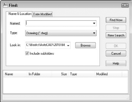
To search for drawings with the Windows' Search feature, choose Start
You can specify drawing properties that you can use in the DesignCenter and even in Windows Explorer. These properties are therefore available to people who can access your drawings but who don't have AutoCAD or AutoCAD LT.
To specify drawing properties, choose Application Button
On the Summary tab, you can specify a title, subject, author, and keywords. You can also write comments. At the bottom of the dialog box, you can specify a base for relative hyperlinks in the drawing. For example, you could use www.companyname.com as the base. AutoCAD or AutoCAD LT would then attach this base to the beginning of links in the drawing.
You can also use the Custom tab to create custom properties and give them values. This lets you create a simple database of your drawings that you can search by using the DesignCenter's Find dialog box. When you're done, click OK.
To access a drawing's properties in Windows Explorer, navigate to the drawing and right-click it. Choose Properties from the shortcut menu.
Note
The Express Tools contain a command, PROPULATE (on the command line, type propulate
In these days of collaboration and interconnectivity, maintaining security is an important issue. Two features help you to keep your designs secure: password protection and digital signatures.
Password protection ensures that unauthorized people don't open your drawings. You create a password when you save a drawing.
Note
AutoCAD LT does not offer password protection.
To create a password for a drawing, type securityoptions
Warning
Before adding a password, save the drawing under another name or in a different location so that you have a copy. If you lose or forget the password, you won't be able to open the drawing. You can turn password protection off for network installations of AutoCAD.
To password-protect a drawing:
Type a password in the text box.
If you also want to encrypt drawing properties that identify the drawing, such as the title, author, subject, and keywords, check the Encrypt Drawing Properties check box.
Click OK.
The Confirm Password dialog box appears. Retype the password.
Click OK.
You can also change or remove a password:
The dialog box displays the current encryption type. To specify a different encryption, click Advanced Options. Choose a new encryption type from the list and a key length, and then click OK.
When a password-protected drawing is opened, the Password dialog box appears. To open the drawing, type the password and click OK.
A digital signature uses software that confirms who signed the drawing and that it has not been changed, as well as nonrepudiation (so that signers cannot claim that they never signed the drawing). To use a digital signature, you need to purchase a digital ID. You can use digital IDs in both AutoCAD and AutoCAD LT.
Generally, you would use a digital signature when you send a drawing to someone else. That person can then verify that the drawing is from you and has not been changed. If the person sends the drawing back to you, you can verify that the person has not changed the drawing, because changing the drawing invalidates the digital signature.
To attach a digital signature to a drawing, follow these steps:
Choose Application Button
Check the Attach Digital Signature after Saving Drawing check box and choose a digital signature.
To place a time stamp on the drawing, choose one of the options from the Get Time Stamp From drop-down list.
To add a comment (that appears when the drawing is opened), type the text in the Comment text box.
Click OK.
When a digitally signed drawing is opened, the Digital Signature Contents dialog box appears, verifying the digital signature and the fact that the drawing has not been changed since it was signed. Click Close to close the dialog box.
Note that making any changes to the drawing invalidates the digital ID. If you make changes or try to save a drawing with an attached digital signature, a message appears asking you whether you want to continue. When you re-open the drawing, the Digital Signature Contents dialog box appears, displaying the fact that the digital signature is invalid.
A drawing with a valid digital signature has a checkmark attached to its icon in Windows Explorer. The drawing itself also sports an icon in the status bar.
Note
Users who don't have the Digital Signature feature can download the Digital Signature Verifier, a free application to verify digital signatures on signed drawings. The Digital Signature Verifier is available from the Autodesk Web site at http://usa.autodesk.com/adsk/servlet/item?siteID=123112&id=877495. (You can also go to www.autodesk.com and do a search on Digital Signature Verifier.)
A drawing references several types of outside files, and you often need to keep track of these files, especially when you send a drawing to someone else or move it to another computer. Also, the referenced files may be moved, even if the drawing stays in the same place. Without these outside files, the drawing is not complete.
Note
AutoCAD LT does not include the Reference Manager.
Outside files include the following:
Other drawings (xrefs, DWF, PDF and DGN underlays)
Text fonts
Shape files
Images
Plot configurations
The Reference Manager not only lists referenced files, but also enables you to change saved reference paths so that the drawing can find the needed files. You don't even need to open the AutoCAD drawing, because the Reference Manager is a stand-alone application.
Note
The External References palette helps you manage xrefs. For more information, see Chapter 19.
To open the Reference Manager, choose Start
To add drawings to the Reference Manager, click Add Drawings and select the drawings. If a drawing has xrefs, you see a message asking whether you want to add the xrefs. To add them, click Yes.
The left pane of the Reference Manager contains a tree view of the drawings that you've added and external references, if any. The right pane is a Reference list and displays the specific external files associated with the added files. You can choose View
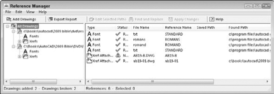
Note
Reference Manager does not find text fonts that are not used in a text style, TrueType fonts that are not saved in the Windows Fonts folder, OLE links, hyperlinks, database file links, PMP files, and external references to URLs on the Web.
To modify the path of an external reference so that a drawing can find it, follow these steps:
Close any drawings or files that you might need to access.
Choose a drawing in the left pane.
Right-click the external reference in the Reference list that you want to change, and choose Edit Selected Paths. (You can also choose Edit Selected Paths from the Reference Manager toolbar.)
Tip
You can also choose Find and Replace to change all references that use a certain saved path, and replace them with a new path. Use this feature when you have a large number of drawings that need paths to changed referenced files.
Type in a new path, or use the Ellipsis button to browse to the location. Click OK.
From the Reference Manager toolbar, choose Apply Changes. A summary message appears to confirm that the drawing has been updated.
To create a list of references, choose Export Report. In the Export Report dialog box, choose the file type that you want to create from the Files of Type drop-down list. You can create the following file types:
Comma-separated values report file (
*.csv)Extensible Markup Language report file (
*.xml)Microsoft Excel Workbook (
*.xls)
Choose a name and a location for the file and then click Save.
Note
The Express Tools contain a command, REDIR (on the command line, type redir
Although AutoCAD 2010 and AutoCAD LT 2010 are stable, nothing can eliminate the occasional crash. Knowing how to re-open a drawing after a crash can save hours of work.
When AutoCAD or AutoCAD LT is loaded, it opens one or more temporary files as part of its normal functioning. Note the following two points regarding these files:
You need to leave room on your hard drive for these files — 50MB is a good starting point.
Never erase current temporary files if you're on a network, because someone else might be using them.
Warning
Never erase temporary files (they have an extension of .ac$) while AutoCAD or AutoCAD LT is open. Normally, they're erased when you close a drawing. Others are erased when you close the program.
However, if the program or your entire computer crashes, you may be left with one or more .a$ files. A good guideline for erasing .a$ files is to only erase those from yesterday or earlier. Leave today's alone.
Tip
If you don't see the date and time of the files in Windows Explorer, choose View
You can also specify where you want these temporary files. You might want to place them on a hard drive with more room. If you're on a network, you might want to place them on your local drive so that there is less traffic back and forth on the network. To find or change the current location, follow these steps:
Choose Application Button
Click the plus sign next to Temporary Drawing File Location to display the current location.
If you want to change the location, click Browse.
In the Browse for Folder list, find and choose the desired folder and click OK.
Click OK to close the Options dialog box.
The most common cause for a corrupted drawing file is a program crash, but power surges and system crashes can also be causes. If AutoCAD or AutoCAD LT detects an error in a file during loading, it attempts to fix the problem automatically. In many cases, it is successful.
When it isn't, you can try the AUDIT and RECOVER commands. These commands search the database for errors and try to fix them. If they cannot fix an error, they simply move on, letting you recover at least part of the file.
If you have a drawing open and see an error message that AutoCAD or AutoCAD LT can't read the file or part of it, follow these steps:
Choose Application Button
At the
Fix any errors detected? [Yes/No] <N>:prompt, type y
Watch the screen as it displays messages for errors.
Use RECOVER when you can't even load the drawing. Follow these steps:
Open a new drawing.
Choose Application Button
In the Select File dialog box, choose the corrupted drawing file and click Open. The recovery process starts and displays the results in the Text window.
Tip
The RECOVERALL command lets you select a drawing and run RECOVER on that drawing as well as all associated xref files. (See Chapter 19 for more on xrefs.)
The DWGCHECK system variable controls how your drawings open when they have errors. Look up this system variable in Help to find a setting that gives you the information and control that you need. Here are some other tips for opening a recalcitrant drawing:
Open a new drawing and choose Insert tab
Open a new drawing and choose Insert tab
If the drawing crashes just when it looks like it has almost loaded, try again; however, this time, press Esc repeatedly until the loading is complete. This procedure aborts the regeneration of the drawing, which may be causing the crash due to corrupt objects. Then use the AUDIT command.
If you can open the drawing but objects are not displayed, try the following:
Choose Application Button
Use the WBLOCK command to save the drawing as a new file.
Save the drawing as a DXF file. (See Chapter 27 for more on the DXF file format.)
Choose Application Button
Thanks to Darren Young of Minnesota CADWorks, Inc., (www.mcwi.com) for these suggestions.
If you can't repair a drawing, perhaps you have an archived copy that you can use. If not, AutoCAD and AutoCAD LT automatically create backup drawings that have the same name as your drawings, but with a .bak filename extension. You can change the extension to .dwg and open it. You may also find one of the .a$ drawings. You can also try changing the extension of this file to .dwg.
Tip
If your computer doesn't show filename extensions for BAK and A$ drawings, open Windows Explorer and choose Tools
If you want to troubleshoot a persistent crash, try turning on the log file. Choose Application Button
Note
The Express Tools contain a command, MOVEBAK (on the command line, type movebak
Yes, AutoCAD does occasionally crash. You may see a message with a Continue button, which you can click to try to continue working on your drawing. If not, the Drawing Recovery Manager tries to make recovering from a crash easy by displaying available backup drawings for you. You see a Drawing Recovery message explaining the process of recovering a crashed drawing.
The Drawing Recovery Manager palette then opens, where you see a list of drawings that are available for recovery, as shown in Figure 26.26. You can select one to see it in the drawing area. You can easily and quickly choose any one of these and open them to see which one you want to continue working with. AutoCAD automatically deletes old drawing recovery files.
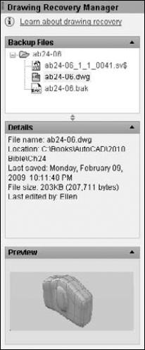
Figure 26.26. The Drawing Recovery Manager displays backup drawings in one place so that you can open them after a crash.
After a crash, the AutoCAD Error Report window opens so that you can send information to Autodesk about the crash. This information helps Autodesk design AutoCAD to be more stable.
When you upgrade to a new release, you need to understand how to work with drawings from earlier releases. Also, you may need to send drawings to clients or colleagues who have an earlier release. AutoCAD 2010 uses a new format, and the same goes for AutoCAD LT. Therefore, AutoCAD 2010 and AutoCAD LT 2010 save in the 2010 format. You cannot open a 2010 drawing in earlier releases. You can save your AutoCAD 2010 drawings in the following earlier drawing formats:
AutoCAD 2007/AutoCAD LT 2007 Drawing (
*.dwg). This format includes AutoCAD and AutoCAD LT 2008 and 2009.AutoCAD 2004/AutoCAD LT 2004 Drawing (
*.dwg). This format includes AutoCAD and AutoCAD LT 2005 and 2006.AutoCAD 2000/LT 2000 Drawing (
*.dwg). This format includes 2000, 2000i, and 2002.AutoCAD R14/LT98/LT97. This is the earliest version you can save to in DWG format.
AutoCAD R12/LT 2 DXF (
*.dxf). To go back earlier than AutoCAD R14/AutoCAD LT 97, you need to save to DXF format. See Chapter 27 for more about the DXF format.
Choose Application Button
In this chapter, I covered various methods for managing drawings. You read about the following:
Using the DesignCenter to access drawing components
Using tool palettes to access drawings, blocks, and hatches
Maintaining CAD standards, including checking a drawing against a standards drawing and translating layers
Understanding the Communication Center
Renaming named objects
Working with sheet sets
Organizing your drawings, including archiving drawings, finding them, and setting properties for them
Maintaining security of your drawings with a password and digital signatures
Using the Reference Manager to keep track of external files referenced in a drawing
Handling errors and crashes
In the next chapter I cover how to use AutoCAD or AutoCAD LT with other applications.