
Specifying points in a drawing is one of the most fundamental tasks you do in AutoCAD and AutoCAD LT. Unless you know how to specify a point, you can't draw anything real, whether a house or a gasket. Most objects you draw have a specific size, and you need to specify that information. You draw lines, arcs, and circles by specifying the coordinates of points on the screen. As with most tasks, AutoCAD and AutoCAD LT offer many ways to accomplish this.
AutoCAD and AutoCAD LT work the same way as the graphs with X and Y axes that you plotted in high school. Look at two displays of the User Coordinate System (UCS) icon, as shown in Figure 4.1. The UCS icon on the left is the default for 2D drawing; the one on the right is the default for 3D drawing and includes the Z axis. In this chapter, I focus on the X and Y axes.
Note
The UCS icon can take on different appearances. See Chapter 8 for details. For information on the UCS icon in 3D work and 3D coordinates, see Chapter 21.
The X arrow points along the X axis in the positive direction. This means that as you go in the direction of the arrow, the X coordinates increase. The Y arrow points along the Y axis in the positive direction. Using this system, every 2D point on the screen can be specified by using X and Y coordinates. This is called a Cartesian coordinate system. The universal convention is to place the X coordinate first, and then a comma (but no space), and then the Y coordinate. By default, the intersection of the X,Y axes is 0,0. Use negative numbers for points to the left of the X axis or below the Y axis.
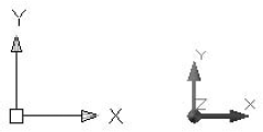
Figure 4.1. The UCS icon shows the direction of the X and Y axes. If you're in a 3D display, you also see the Z axis.
When you draw in AutoCAD or AutoCAD LT, you draw in undefined units. A line from point 3,0 to point 6,0 is three units long. While you're drawing, these units can be anything — a millimeter, a centimeter, a meter, an inch, a foot, or a mile. In reality, you should know exactly what the units represent. After all, you don't want your 36-foot-wide house to end up 36 inches wide!
When you set up a drawing, you specify how units are displayed — for example, whether partial units show as decimal points or fractions. (I cover units in Chapter 5.) However, you don't actually specify what the units represent until you print or plot your drawing — covered in Chapter 17.
To ensure accuracy, you should draw full size. If you're drawing a plan for a factory that will be 120 feet long, for example, you create lines with those measurements. On the screen, you can zoom in to see small details or zoom out to see the whole factory, so that you have no reason not to use the actual line lengths. It's only when you need to print those 120-foot-long lines on a real sheet of paper that you have to specify how to plot out your drawing at a reduced scale.
Users are typically familiar only with the type of notation used in their own field of specialty, whether scientific, architectural, engineering, or whatever. However, you should be at least somewhat familiar with all the major forms of measurement notation.
Note
If you are using engineering or architectural units, AutoCAD and AutoCAD LT display parts of inches (fractions) differently than the format you must use to type them in. You must type in coordinates without any spaces because in AutoCAD a space is equivalent to pressing Enter, and that ends your input. Use a hyphen between whole and partial inches — for example, 3′2-1/2″. (You can omit the ″ after the number because inches are assumed in engineering and architectural units if no symbol follows a number.) However, this appears on the status bar as 3′-2 1/2″. This can be confusing because the hyphen is in a different place, and you see a space between the whole and partial inches.
One of the more basic ways to specify the location of an object is to type its coordinates by using the keyboard. You can enter several types of coordinates. Use the type of coordinates that suit your specific situation.
Tip
If you need to enter a coordinate that you've typed recently, use the Recent Input feature. Right-click and choose Recent Input from the shortcut menu. Then choose the coordinate that you want from the list that appears.
Dynamic Input enables you to enter text input near the cursor. In Chapter 3, I explain how to use the Dynamic Input tooltip for commands and command options. Here I explain how to use it to enter coordinates.
You can type 2D coordinates in the Dynamic Input tooltip in the same way that you type them on the command line — in the format x,y. You can press Tab between the X and Y coordinates instead of typing a comma, but typing the comma is probably easier and therefore more accurate.
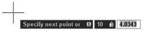
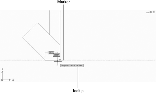
When you draw a line, after you specify the first point, you see only one tooltip box because AutoCAD assumes that you want to enter only the distance, using the current angle of the temporary line shown on the screen. However, as soon as you type a comma or press the Tab key, a second box appears so that you can enter the Y coordinate, as shown in Figure 4.2. The same situation applies when you want to move or copy an object and want to specify an X,Y displacement.
In Figure 4.2, note the lock next to the X coordinate. Before you type any part of the coordinate, both the X and Y values vary as you move the mouse. When you enter a value for the X coordinate, you fix this value, as the lock indicates. However, the Y coordinate is still unlocked until you type a value.
You can specify how Dynamic Input works for coordinates that you type. Changing the settings gives you very different results when you type coordinates, so you should familiarize yourself with the settings. To specify settings for the Dynamic Input feature, right-click the Dynamic Input button on the status bar and choose Settings to display the Dynamic Input tab of the Drafting Settings dialog box, as shown in Figure 4.3.
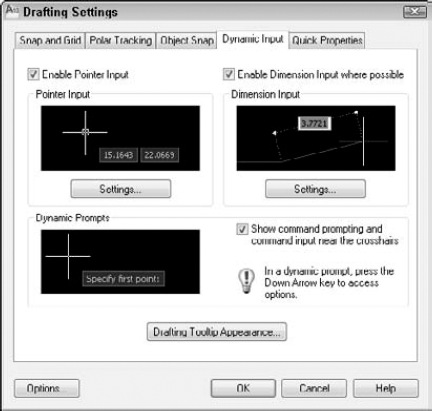
Figure 4.3. Use the Dynamic Input tab of the Drafting Settings dialog box to specify how your Dynamic Input works when you type coordinates.
The Enable Pointer Input check box is selected by default, which means that the Dynamic Input tooltip includes an input box where you can type coordinates at the start of any command. If you uncheck this check box, you see these first coordinates only on the command line as you enter them. However, whether the check box is checked or not, as long as the Dynamic Input button is selected on the status bar, you see the input box for subsequent coordinates in a command. For example, if you are drawing a line, and the Enable Pointer Input check box is not checked, you don't see coordinates that you type for the start point in the Dynamic Input tooltip, but for the next point, you see the input box and coordinates that you type appear in that box.
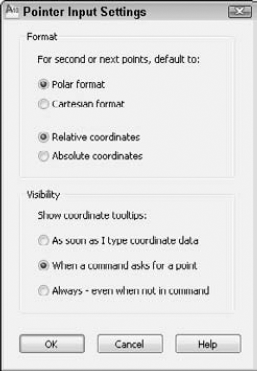
Click the Settings button to open the Pointer Input Settings dialog box. Here you can make the following choices:
Default format for second or next points. You can choose to default to polar or Cartesian format. The default is polar format, which shows distances. I explain polar format in the "Polar coordinates" section, later in this chapter. You can also choose between relative and absolute coordinates, as shown in Figure 4.4. The default is relative coordinates, which indicate a distance and direction from a previously specified point. I explain both absolute and relative formats in the next few sections of this chapter.
Tooltip visibility. You can specify that you see the tooltip only when you start typing a point in response to a prompt, automatically at a prompt for a point (the default), or always.
Warning
The settings in this dialog box are very important for determining how all of your coordinate entries work when Dynamic Entry is turned on. If you are upgrading from an earlier version of AutoCAD, you are used to the entry of X,Y coordinates denoting absolute, not relative, coordinates. However, with Dynamic Input turned on, the default is relative coordinates. This is a great default and will speed up your coordinate entry, but can be very confusing if you are unaware of this setting or where to change it.
The Enable Dimension Input Where Possible check box is selected by default. This section has nothing to do with dimensions! Instead, it refers to distances or lengths as well as angles, as opposed to points or coordinates. With this check box selected, after you indicate a first point, such as the start of a line or the center of a circle, you see a dimension tooltip that shows the length of the line segment or radius of the circle, as shown in Figure 4.5. You specify the length by typing in this tooltip. If you uncheck the check box, you don't see this dimension tooltip.
Click the Settings button in this section of the dialog box to open the Dimension Input Settings dialog box. Here you can change settings relating to dimension input during grip editing. I discuss grip editing in Chapter 10.
The Show Command Prompting and Command Input Near the Crosshairs check box enables the display of command prompts and your input in response to these prompts in the Dynamic Input tooltip. This part of Dynamic Input is supposed to take the place of the command line. However, the prompts are not an exact echo of what you see on the command line, and certain prompts do not appear in the tooltip.
Note
If you like Dynamic Input, try turning off the command line by using the COMMANDLINEHIDE command or by pressing Ctrl+9. You can get the command-line window back with the COMMANDLINE command or by pressing Ctrl+9 again. You can also undock the Command Line window, right-click its title bar, and choose Auto-hide. Then the Command Line window collapses to just its title bar; when you place the cursor over it, it automatically expands again.
Click the Drafting Tooltip Appearance button to open the Tooltip Appearance dialog box. Here you can change the color of the tooltip, change its size and transparency, and apply the settings to all drafting tooltips in AutoCAD.
The default Dynamic Input settings ensure that your input in the tooltip is always interpreted as polar, relative coordinates. However, you may want to override this setting for an individual coordinate. You can override this setting by using a symbol before your X coordinate as you type it. AutoCAD provides three overrides that you can use:
Absolute. To override the default setting of relative coordinates and enter an absolute coordinate, type #. For example, you could type #0,0 to specify the 0,0 coordinate. See the next section of this chapter for more information on absolute coordinates.
Relative. If you have set your Dynamic Input for absolute coordinates, you can enter @ to override the setting and type a relative coordinate. For example, you could type @3,4. See the "Relative Cartesian coordinates" and "Polar coordinates" sections for a detailed explanation of relative coordinates.
World. Normally, coordinates that you type are interpreted in the current User Coordinate System. The default coordinate system is called the World Coordinate System. If you have created a custom coordinate system but want to enter a World Coordinate System coordinate, type * before the X coordinate. For more information, see Chapter 8 (for two-dimensional drawings) and Chapter 21 (for three-dimensional drawings).
Tip
To temporarily turn off Dynamic Input, press and hold the F12 key. You might do this while you are picking points if you find that the tooltip obscures objects that you need to see. As soon as you release the F12 key, Dynamic Input returns.
When you type a line and enter the actual coordinates, such as a line from point 3,2 to 6,9, you are using absolute Cartesian coordinates. Absolute coordinates are measured from 0,0.
If you have Dynamic Input on with the default setting of relative units, you must enter the # symbol before entering the X portion of an absolute Cartesian coordinate when specifying the second or next point, as explained in the previous section. In this exercise, you practice entering absolute Cartesian coordinates.
STEPS: Entering Absolute Cartesian Coordinates
Start a new drawing by using the
acad.dwtoracadlt.dwttemplate. Close any palettes that may be open.
Choose Home tab

Specify first point:
−10,−5Specify next point or [Undo]:
21,−5Specify next point or [Undo]:21,49Specify next point or [Close/Undo]:−10,49Specify next point or [Close/Undo]:c(to close the rectangle)Most of the lines are off the screen. By default, a new drawing starts with 0,0 at the lower-left corner of your screen; therefore, negative coordinates do not show.
Choose View tab
Note
If the prompt responds with
Invalid PointorPoint or option keyword required, you have entered a coordinate incorrectly. Try typing the coordinate again. Also, don't forget that you can undo a command if you make a mistake. (See Chapter 3 for details.)Start the LINE command again and follow these prompts:
Specify first point:
−8,−2Specify next point or [Undo]:19,−2Specify next point or [Undo]:19,21.5Specify next point or [Close/Undo]:−8,21.5Specify next point or [Close/Undo]:cOnce more, start the LINE command and follow these prompts:
Specify first point:
−8,22.5Specify next point or [Undo]:19,22.5Specify next point or [Undo]:19,46Specify next point or [Close/Undo]:−8,46Specify next point or [Close/Undo]:cIf you changed the Dynamic Input settings in Step 1, you should change them back. Right-click the Dynamic Input button on the status bar and choose Settings. In the Pointer Input section, click the Settings button. In the Pointer Input Settings dialog box, click the Relative Coordinates option. Click OK twice to return to your drawing.
Save this drawing in your
AutoCAD Biblefolder asab04-01.dwg.
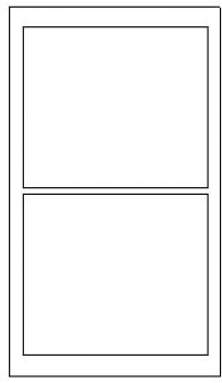
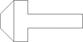
You can now see that you've drawn a simple window, as shown in Figure 4.6.
Two questions may have occurred to you during this exercise. First, isn't there a better way of entering absolute coordinates? Typing them in is slow and prone to error. Second, how do you know the absolute coordinates for what you're drawing? Read on for the answers.
In practice, you usually don't know the absolute coordinates of the points you need to specify in order to draw an object. Whether you're drawing an architectural layout, a physical object (as in mechanical drawing), or an electrical schematic, you don't have X,Y coordinates from which you can work. However, you often do have the measurements of what you're drawing. Usually, you start from any suitable point and work from there. In this situation, you know only the length of the lines you're drawing (if you're drawing lines). Real life doesn't have a 0,0 point. Relative coordinates were developed for these situations.
Relative coordinates specify the X and Y distance from a previous point. They are called relative coordinates because they have meaning relative only to a point previously specified. Suppose that you need to draw a window. You can start the window from any point. From there, you have the measurements you need.
If you have Dynamic Input on — set to the default option of relative units — X,Y coordinates are automatically relative. If you have Dynamic Input off or have set Dynamic Input to absolute coordinates, as described earlier in this chapter, you specify that the coordinates are relative by using the @ symbol. For example, if you start a line by picking any point with the mouse, and you know it should be two units long, you can specify the next point as @2,0. The result is a line starting with the first point you picked and ending two units along the X axis, as shown in Figure 4.7. The line is horizontal because the Y coordinate is 0. In a relative coordinate, this means that the Y distance does not change.
Relative Cartesian coordinates are often used for lines drawn at 90-degree angles (that is, they are either horizontal or vertical). These are called orthogonal lines. However, when you create a diagonal line from point 3,3 to point @2,5, the length of the line is not immediately obvious.
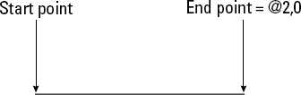
Figure 4.7. A line whose start point could be anywhere and whose endpoint is specified with the relative point @2,0 is a horizontal line two units long.
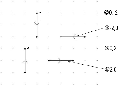
When you specify a positive number, such as the 2 in @2,0, the direction is positive. If you want to draw a line in the negative direction of an axis, type a minus sign before the number. Figure 4.8 shows how to draw lines in four directions, using relative coordinates.
Another common situation is to know the distance and angle of a point from either 0,0 or a previous point. In this case, you can use polar coordinates, which can be either absolute or relative. Most commonly, you use relative polar coordinates.
Polar coordinates take the form distance<angle. (To type the angle symbol, use the less-than symbol on your keyboard.) If you have Dynamic Input on, set to the default options of relative coordinates, polar coordinates are automatically relative. If you have Dynamic Input off or have set Dynamic Input to absolute coordinates, as described earlier in this chapter, you need to add the @ sign before a relative polar coordinate. If you also have the default option of polar format selected, you first see coordinates in polar format. Enter the distance, press the Tab key, and then enter the angle. You can also type the angle (<) symbol instead of using the Tab key. To switch to Cartesian format, just type a comma between the X and Y coordinates.
With Dynamic Input on, angles are measured from 0 to 180, with 0 to the right, going either clockwise or counterclockwise. Watch the dotted lines near the angle's tooltip to see exactly what the angle shown in the tooltip is measuring. You can use negative angles. With Dynamic Input off, angles are measured counterclockwise, with 0 to the right, ranging from 0 to 360.
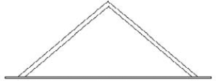
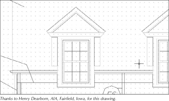
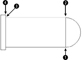
In the following series of steps, you draw part of a portico, the decorative molding above a door or window. You'll use architectural units. In this case, only inches are used, which don't need to be specified. You can specify feet by using an apostrophe (also called a prime) after any number.
When typing architectural units, partial inches are indicated by fractions in the form a/b. You need to separate the fraction from the whole inches by a hyphen. This can be a little confusing because the hyphen is also used for negative numbers. For example, to draw a horizontal line of 5¼ inches in the negative direction of the X axis, you would type -5-1/4,0. (The 0 indicates no change in the Y axis because it is a horizontal line.)
Note
The drawing used in this exercise on using relative and polar coordinates, ab04-a.dwg, is in the Drawings folder on the DVD.
STEPS: Using Relative and Polar Coordinates
Open
ab04-a.dwgfrom the DVD. Close any palettes that may be open.As you move your mouse around, notice that the coordinates displayed on the status bar are in architectural units (that is, in feet and inches). If the coordinates are grayed out, click them to turn them on.
Save the drawing in your
AutoCAD Biblefolder asab04-02.dwg.Note
The next steps involve some complex typing. If you get an error message, try typing the coordinate again. If you realize you made a mistake after ending the command, click Undo on the Standard toolbar. This exercise assumes that you are using the default Dynamic Input settings of polar format and relative coordinates and that Dynamic Input is on. See the "Using the Dynamic Input tooltip to enter coordinates" section earlier in this chapter for details.
Choose Home tab
Specify first point:
Pick any point at the lower-left corner of your screen. Specify next point or [Undo]:0,-3/4Specify next point or [Undo]:75-1/4,0Specify next point or [Close/Undo]:0,3/4Specify next point or [Close/Undo]:cStart the LINE command again. Follow the prompts:
Specify first point:
.This starts the line at the last endpoint you specified. Specify next point or [Undo]:4-3/4,0Specify next point or [Undo]:43<40Specify next point or [Close/Undo]:43<-40Specify next point or [Close/Undo]:-2-1/4,0Specify next point or [Close/Undo]:39-7/8<140Specify next point or [Close/Undo]:39-7/8<-140Specify next point or [Close/Undo]:to end the command.Save your drawing. You have created a portion of a portico, which goes over a window of a house, as shown in Figure 4.9.
Tip
You can type @
Notice that using relative coordinates, both Cartesian and polar, is much more realistic than using absolute coordinates. However, typing in coordinates is still awkward. Typing in coordinates is often the only way to get exactly what you want. Nevertheless, several other techniques for specifying coordinates are easier in many circumstances. I discuss these techniques in the next few sections.
One shortcut for entering coordinates is direct distance entry. After you specify the start point of a line, at the Specify next point or [Undo]: prompt, simply move the mouse cursor in the direction you want the line to go and type in the line's length. It works best in orthogonal mode or with polar tracking (discussed in the following section), which makes specifying the exact angle easy.
Note
You can use direct distance entry for any command that requires you to specify a distance and a direction, including both drawing and editing commands.
Lines drawn at 0, 90, 180, and 270 degrees are called orthogonal lines. When in orthogonal mode — ortho for short — you can only draw orthogonal lines with the mouse. Ortho Mode also affects editing. For example, with Ortho Mode on, you can move objects only vertically or horizontally. Combined with snap and grid, Ortho Mode makes drawing easier and more efficient. Ortho Mode is also great for direct distance entry.
Note
Orthogonal mode only affects points picked directly on the screen by using your mouse. Any relative or absolute coordinates that you type in the Dynamic Input tooltip or on the command line override orthogonal mode. For example, if you use a polar coordinate of 5<45 in the Dynamic Input tooltip, you'll get a line at an angle of 45 degrees, even when Ortho Mode is on.
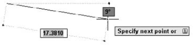
Polar tracking guides you, using a tooltip and vector line, when you want to draw (or edit) at an angle other than the four orthogonal angles, as shown in Figure 4.10. You can use polar tracking for orthogonal angles as well. If you have Dynamic Input on, just look for the word "Polar" to distinguish between the Dynamic Input and the polar tooltips.
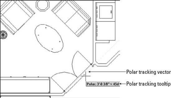
Figure 4.10. When polar tracking is on, a tooltip appears when you move the cursor close to one of the polar angles. Here you see a tooltip indicating an angle of 45 degrees.
Polar tracking makes it easy to use direct distance entry to specify distances for many angles. To use polar tracking, you first set the angles that you want to use.
To set polar tracking, you can define two types of angles:
Increment angle. To set the increment angle, click the Increment Angle drop-down arrow, where you can pick from angles that range from every 90 degrees to every 5 degrees. You can also type your own incremental angle in the text box. Polar tracking will then apply to that angle and its multiples.
Additional angles. If you think that you'll need other angles, check Additional Angles, click New, and then type in an angle. You can add up to ten angles. Note that additional angles are not incremental angles — if you type 35, only 35 degrees will be marked, not 70 degrees or other multiples of 35. To delete an additional angle, select it and click Delete.
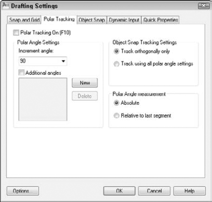
To customize how polar tracking works, click Options in the Drafting Settings dialog box to open the Options dialog box with the Drafting tab on top. The following settings in the AutoTracking Settings section apply to polar tracking:
Display polar tracking vector turns on and off the polar tracking vector, which is the faint dotted line that extends to the end of the screen.
Display AutoTrack tooltip turns on and off the tooltip that tells you the distance and angle.
To use polar tracking, you need to move the cursor slowly through the angles to allow time for the calculation and display of the vector and tooltip. Suppose that you're drawing a line. Specify the start point. To specify the second point, move the cursor in the approximate angle of the line you want to draw. When you see the polar tracking vector and tooltip, leave the mouse where it is and type the length of the line. Then press Enter to create the line with the proper length and angle. You'll find this method easier than typing polar coordinates for lines with angles specified in your polar tracking settings.
Tip
Turn on NumLock on your keyboard and use the numerical pad for typing lengths. Use the Enter key on the numerical pad as well.
You can specify a polar angle for just one command. If you're drawing a line, after specifying the first point, for example, type the angle preceded by the angle symbol (<). The next segment is then locked to that angle while you type its length. A polar angle specified in this way is called a polar override angle because it overrides the current polar angles in effect. Of course, a polar override is not faster than simply typing a polar coordinate, but it does let you see the angle of the line segment before you type its length.
In the following exercise, you practice using direct distance entry with Ortho Mode and polar tracking.
Note
The drawing (ab04-b.dwg) used in the following exercise on using direct distance entry with Ortho Mode and polar tracking is in the Drawings folder on the DVD.
STEPS: Using Direct Distance Entry with Ortho Mode and Polar Tracking
Open
ab04-b.dwgfrom the DVD. Close any palettes that may be open.

Choose Home tab
Move the mouse horizontally to the right and then type .5
Move the mouse up vertically (in the 90-degree direction) and then type .5
Move the mouse horizontally to the right and then type 2
Move the mouse up in the 90-degree direction and then type .5
Move the mouse to the left in the 180-degree direction and then type 2
Move the mouse up in the 90-degree direction and then type .5
Move the mouse to the left in the 180-degree direction and then type .5
Type c

Start the LINE command again. Press Enter to start the new line from the most recent point. At the
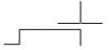
Specify next point or [Undo]:prompt, move the cursor diagonally up and to the left so the line is approximately in the 135-degree direction. When you see the tooltip confirming the angle, release the mouse button and type .7071Move the cursor up until you see the polar tracking tooltip confirming a 90-degree angle. Type .5
Move the cursor diagonally in the 45-degree direction until you see the tooltip. Type .7071
Save your drawing. It should look like Figure 4.13.
As you work, you can refer to the coordinate display on the status bar. This display helps you know where your cursor and objects are when you draw and is also helpful when editing, by informing you how far and in what direction you are moving or copying objects.
Note
You can set the Dynamic Input tooltip to show coordinates all the time, even when you're not in a command. See the "Specifying Dynamic Input settings" section, earlier in this chapter.
AutoCAD and AutoCAD LT have three coordinate display modes:
Dynamic absolute coordinates (absolute). Absolute coordinates that change as you move the mouse, as shown in Figure 4.14 on the left.
Static absolute coordinates (off). Absolute coordinates that change only when you specify a point, as shown in Figure 4.14 in the middle. The coordinate display is dimmed.
Dynamic polar coordinates (relative). Polar coordinates that change continuously as you move the mouse, as shown in Figure 4.14 on the right. They appear after you've already specified a point and are ready to specify the next point, as when you're in the process of drawing a line.

The easiest way to change the coordinate display is to click the coordinates area on the status bar. You can also right-click the coordinate display and choose Relative, Absolute, or Off from the shortcut menu.
For purposes of this chapter, I ignore the Z coordinate that follows the X and Y coordinates (in AutoCAD only). In two-dimensional drawings, the Z coordinate is always zero.
In the following exercise, you practice using the coordinate display options. You can do this exercise with any new or existing drawing open on the screen. If you have Dynamic Input on, compare the display in the Dynamic Input tooltip and the display on the status bar.
STEPS: Using Coordinate Display Options
Look at the coordinate display on the status bar. It should be shown in black. If the coordinates are shown in gray, click the coordinates.
Move the mouse around in a few directions. Notice how the coordinates constantly change with the mouse movement.
Right-click the coordinates and choose Off. The coordinate display is grayed out.
Move the mouse around again. The coordinate display does not change with the movement of the mouse.
Choose Home tab
Watch the coordinate display as you pick any point at the
Specify next point or [Undo]:prompt.Pick several other points and watch as the coordinate display changes only when you pick a point. This is the static coordinate display.
Click the coordinates again without ending the LINE command.
Move the mouse to another point that you would like to pick, but watch the coordinate display before you pick the point. This time, the length and angle of the new line segment are shown. These are dynamic polar coordinates.
Pick a few more points, watching the polar coordinates.
Right-click the coordinates and choose Absolute to return to dynamic absolute coordinates.
Press Enter to end the LINE command. Do not save your drawing.
The easiest and quickest way to specify coordinates is to pick them directly on the screen with the mouse. Several techniques are available to help you do so accurately.
You can adjust the size of the crosshairs that cross the cursor. By default, they are 5 percent of screen size. To change the crosshair size, choose Application Button
The SNAP command is often an alternative to tedious entry of coordinates. This command restricts the cursor to an incremental distance that you choose, such as 0.5 units. You can set the snap size to anything you want. For example, if all your measurements are rounded off to the nearest 0.25 units, you can set your snap to 0.25.
The snap technique is not very useful when you need to draw to three or more decimal places of accuracy. And when you're zoomed out in a large drawing, the snap points may be so close together that you cannot easily find the one you want. But in the right situation, snap is one of the quickest, most accurate drawing techniques available. AutoCAD and AutoCAD LT provide two types of snap settings, Grid Snap and PolarSnap.
When you snap to a grid, an invisible grid becomes active (which you can make visible by using the GRID command, discussed in the next section). As soon as you turn on Grid Snap, the mouse cursor can move only to the Grid Snap points.
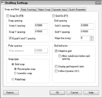
Figure 4.15. The Snap and Grid tab of the Drafting Settings dialog box. (The AutoCAD LT dialog box is slightly different.)
Note
In Chapter 8, I discuss rotating the angle of the snap and grid. Chapter 8 also discusses Isometric snap, used for isometric drawing.
Usually you want the X spacing (going across) to be the same as the Y spacing (going up and down). By default, the Equal X and Y Spacing check box is selected, so you need to specify only the X spacing; the Y spacing changes automatically to equal the X spacing. X and Y spacing will be different only if you type a different number in the Snap Y Spacing text box.
After you set polar tracking settings, discussed earlier in this chapter in the "Polar tracking" section, you can snap to increments along the polar angles you have set. When PolarSnap is on, the polar tooltip only shows distances in increments of the snap setting. When you see the distance you want, just click. PolarSnap makes it easy to draw accurately without having to type coordinates.
To use PolarSnap, follow these steps:
Right-click the Snap Mode button on the status bar and click Settings to open the Drafting Settings dialog box with the Snap and Grid tab displayed.
Check PolarSnap in the Snap Type section of the dialog box (refer to Figure 4.15).
Type a distance in the Polar Distance text box.
Click OK to close the dialog box.
Click Snap Mode on the status bar.
Note that PolarSnap and Grid Snap are mutually exclusive. If PolarSnap is on, the cursor will not snap to the grid. Used with polar tracking, PolarSnap is a powerful tool. Remember that you can polar track along orthogonal as well as other angles.
Tip
You can choose either PolarSnap or Grid Snap (switch between them) by right-clicking Snap Mode on the status bar. A shortcut menu lets you choose the type of snap you want, or turn both off.
Some users find the grid annoying, but when you first start to use AutoCAD or AutoCAD LT, you may find it helpful. Even accomplished users can take advantage of the grid, especially when starting a new drawing.
Tip
If you're working with a small snap spacing and the dot grid is too dense, set the dot grid to two or more times the size of the snap spacing.
As with the snap feature, you usually want the X spacing (going across) to be the same as the Y spacing (going up and down). You only need to specify the X spacing; the Y spacing automatically changes to be the same, as long as the Equal X and Y Spacing check box is selected in the Drafting Settings dialog box. X and Y spacing will only be different if you type a different number in the Grid Y Spacing text box.
You can turn on the grid in this dialog box by clicking the Grid On check box, but it's easier to click Grid Display on the status bar (or press F7).
In the following exercise, you practice using PolarSnap and Grid Snap points as well as grid dots.
Note
The drawing used in the following exercise on using snap points and grid dots, ab04-b.dwg, is in the Drawings folder on the DVD.
STEPS: Using Snap Points and Grid Dots
Open
ab04-b.dwgfrom the DVD. Close any palettes that may be open.Save the drawing in your
AutoCAD Biblefolder asab04-04.dwg.
In the Snap Spacing section, the Snap X Spacing should be 0.5.
In the Grid Spacing section, the Equal X and Y Spacing check box should be selected. The Grid X Spacing should be 0.5. Click OK.
On the status bar, click Snap Mode, Grid Display, and Ortho Mode. The grid appears. Make sure that the Object Snap and Object Snap Tracking buttons on the status bar are off.
Choose View tab
Move the mouse around and watch the coordinates on the status bar. (Right-click the coordinate and choose Absolute if they are in static mode.) They show halves of units because you have set the snap to 0.5.
Choose Home tab
Move the mouse around and watch the coordinates. If you don't see polar coordinates (for example, 3.0000<0), right-click the coordinates and choose Relative.
Move the mouse to the right until the coordinates read 8.5000<0 and click. You have drawn a horizontal line with a length of 8.5 units.
Right-click and choose Enter to end the LINE command.
Move the mouse cursor away from the end of the new line and back to it again, and the absolute coordinates appear. They should be 10.5000,2.0000.
Right-click and choose Repeat LINE to start the LINE command again. Use the coordinate display to start the line at 1.5000,1.5000. (For the rest of this exercise, ignore the Dynamic Input tooltip.) Continue to pick points (rather than type them) and draw the following line segments, as shown in the coordinate display:
0.5000<0
3.0000<90
0.5000<180
3.0000<270
End the LINE command.
Start the LINE command and pick points, drawing the following line segments (as shown in the coordinate display) starting from 10.5000,1.50. Then end the LINE command:
0.5000<0
3.0000<90
0.5000<180
3.0000<270
Starting from 2.0000,4.0000 draw an 8.5-unit line at 0 degrees. End the LINE command.
Start the LINE command again. At the first prompt, pick 11.0000,2.0000. Right-click the Snap Mode button on the status bar and choose Settings. In the Snap Type section, choose PolarSnap. (This is equivalent to choosing the PolarSnap On feature on the Snap Mode button's shortcut menu.) In the Polar Spacing section, change the Polar Distance to 0.5. Choose the Polar Tracking tab and set the Increment Angle to 45 degrees. Click OK. Click Polar Tracking on the status bar.
Move the cursor in a 45-degree direction from 11.0000,2.0000 until you see the tooltip. Move along the polar tracking vector until the tooltip says 3.5000 < 45° and click. End the LINE command.
Right-click the Snap Mode button and choose Grid Snap On. Start the LINE command and, at the
Specify first point:prompt, choose 11.0000,4.0000.Right-click the Snap Mode button and choose PolarSnap On. Move the cursor in a 45-degree direction until the tooltip says 3.5000 < 45° and click. End the LINE command.
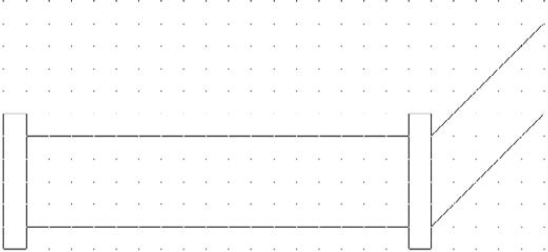
Save your drawing. Your drawing should look like Figure 4.17.
As you no doubt experienced, this is a much easier way to draw compared to typing in coordinates. Note that drawing with Snap on works better when you're drawing small objects. However, even when drawing an office building, you spend a great deal of time working on small details that may be easier to draw with Snap on.
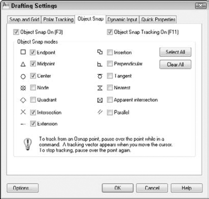
Often you need to draw relative to an existing object. For example, you may need to start a line from the endpoint or midpoint of an existing line. Object snaps (OSNAPS for short) enable you to precisely specify a point by snapping to a geometrically defined coordinate on an existing object. Object Snaps provide a very precise and efficient way to draw.
Here are three ways to specify an object snap:
Right-click, choose Snap Overrides from the shortcut menu, and then choose the object snap that you want from the menu.
Access the Object Snap shortcut menu by holding down the Shift key and right-clicking. Choose the object snap that you want from the shortcut menu.
Type the object snap's abbreviation on the command line.
Note
On multibutton mice, you can customize one of the buttons to show the Object Snap menu. Displaying the Object Snap menu with the click of a mouse button is very convenient. Customizing the mouse is discussed in Chapter 33.
When you specify an object snap, a prompt for that object snap appears on the command line. For example, if you choose a midpoint object snap, you see mid of on the command line. Unfortunately, the Dynamic Input tooltip does not show this prompt.
Tip
When you use Dynamic Input and object snaps together, the tooltip alternates between showing the Dynamic Input tooltip and the object snap tooltip, or displays them as separate tooltips. To keep all the tooltips together, set the TOOLTIPMERGE system variable to 1.
Table 4.1 lists the object snaps. Use the abbreviation to type the object snap from the keyboard.
Table 4.1. Object Snaps
Abbreviation | Uses | |
|---|---|---|
Endpoint | End | Lines, arcs, and so on. |
Midpoint | mid | Lines, arcs, and so on. |
Intersection | Int | Intersection of lines, circles, arcs. |
Apparent Intersection* | App | The intersection that would be created if two objects were extended until they met. |
Extension | Ext | Extends lines, arcs, and so on past their endpoints but in the same direction. After choosing this object snap, pause over the endpoint of a line or arc until you see a small plus sign. As you move the mouse cursor along the extension path, a temporary extension path appears so that you can draw to or from points on the extension path. |
Center | Cen | Circles, arcs, ellipses. |
Quadrant | Qua | Nearest quadrant (0-, 90-, 180-, or 270-degree point) of a circle, arc, or ellipse. |
Perpendicular | Per | Arc, circles, ellipses, lines, multilines, polylines, rays, splines, or construction lines. The Deferred Perpendicular mode lets you draw a line perpendicular from one of these objects. Start the line command and choose the Perpendicular object snap. Click the object that you want to draw perpendicular from and then move the cursor away from that object. You see the Deferred Perpendicular tooltip and a temporary perpendicular line that follows your cursor along the original object. You can then complete the perpendicular line. |
Parallel | Par | Continues a line, polyline, and so on so that it's parallel to an existing line or other straight-line segment. After you choose this object snap, pause over the line you want to draw parallel to until you see a small parallel line symbol. As you move the mouse cursor parallel to the object, a temporary parallel path appears to help you create the parallel segment. |
Tangent | Tan | Starts or continues a line from or to a point tangent with an arc, circle, or ellipse. |
Node | Nod | Point objects. (discussed in Chapter 7) and origin point (defpoint) on dimensions (covered in Chapter 14). |
Insertion | Ins | Insertion point of text (see Chapter 13) or a block (see Chapter 18). |
Nearest | Nea | Nearest point on any object. |
None | Non | Turns off any object snap modes. |
[a] Apparent Intersection also applies to 3D objects that appear to intersect because of the angle of view. | ||
When drawing a line, think of it as having a starting point and an ending point. After the line is drawn, however, both of these points are considered endpoints in terms of object snaps. When picking the endpoint of a line for the endpoint object snap, pick a point on the line closer to the endpoint that you want. The same applies to arcs. Although the arc prompts read Start point and End, both are considered endpoints for purposes of object snaps.
AutoSnap is a feature that helps you work with object snaps. When you move the cursor near the geometric point you have specified, such as an endpoint, you are notified in three ways:
Figure 4.18 shows an endpoint marker and AutoSnap tooltip.
You can customize the AutoSnap feature to suit your needs or make it go away completely if you want. Choose Application Button
In the following exercise, you practice using object snaps.
STEPS: Using Object Snaps
Start a new drawing by using the
acad.dwtoracadlt.dwttemplate. Close any palettes that may be open.Save the drawing in your
AutoCAD Biblefolder asab04-05.dwg.Click Ortho Mode on the status bar to turn on Ortho Mode. If the Object Snap button on the status bar is on, click it to turn off running object snaps (covered in the next section).
Choose Home tab
Specify first point:
2,7.Move the cursor downward. Specify next point or [Undo]:4.Move the cursor to the right. Specify next point or [Undo]:4.Move the cursor up.Specify next point or [Close/Undo]:
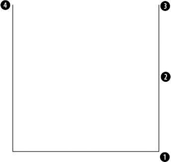
4Specify next point or [Close/Undo]:Press Enter to end the command.Your drawing should look like Figure 4.19. The circled numbers are reference points for this exercise.
Choose Home tab
Specify start point of arc or [Center]:
Right-click. From the shortcut menu, choose Snap OverridesEndpoint. _endp ofMove the cursor to
in Figure 4.19. When you see the endpoint marker and AutoSnap tooltip, click. Specify second point of arc or [Center/End]:Right-click and choose Center. Specify center point of arc:Press Shift and right-click. Choose Midpoint from the shortcut menu. _mid ofMove the cursor to
and pick. Specify end point of arc or [Angle/chord Length]:end.Move the cursor to
and pick.Choose Home tab
Specify center point for circle or [3P/2P/Ttr (tan tan radius)]:
Choose Center from the Object Snap shortcut menu. cen ofMove the cursor over the arc until you see the Center marker and tooltip, and then click. Specify radius of circle or [Diameter]:.75Start the LINE command and use any method you want to draw a line from the endpoint at
Note
When you press Shift and right-click to get the Object Snap menu, the mouse pointer must be in the drawing area. If it is on a toolbar, you get the Toolbars list. If that happens, press the Esc key, or hold down the Shift button and right-click again in the drawing area.
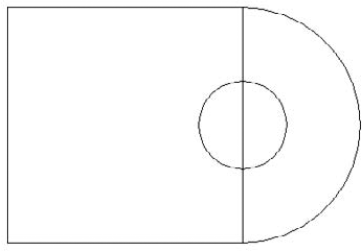
Save your drawing. It should look like Figure 4.20.
The Endpoint object snap is probably the most commonly used of all the object snaps. It would be nice to have a method of using object snaps that you use often without resorting to a menu, toolbar, or keyboard entry. The solution is to set a running object snap, which keeps one or more object snaps on until you turn them off.
Tip
Many users like to work with three or four running object snaps on at once, such as Endpoint, Midpoint, Center, and Intersection. If you can't find the object snap you want because you have several object snaps near each other, press the Tab key to cycle through the object snaps, one by one, until you find the one that you want.
You use the Object Snap button on the status bar to turn on your running object snaps. If you want to turn them off temporarily, just click the Object Snap button or press F3. This capability to toggle running object snaps on and off makes it easy to work with running object snaps on almost all the time, because you can turn them off at the click of a button.
Sometimes you're in the middle of a command and want to turn off an object snap just for a second. You're trying to pick a point and that pesky object snap marker keeps appearing just when you don't want it. Or you may want to turn Snap mode on or off for part of a command. Temporary overrides exist for this purpose. There are two kinds of temporary overrides:
Toggles. You press a key or combination of keys. The setting switches on or off. You then press the same keyboard shortcut to reverse the setting. For example, if you have Ortho Mode on, you can press F8 to turn it off. To turn Ortho Mode back on, press F8 again.
Temporary overrides. You press and hold a key or key combination. The setting switches on or off only while you're holding down the keyboard shortcut. The setting reverts to its original setting when you release the key or key combination. For example, if you have Ortho Mode on, you can press Shift to temporarily turn it off. As soon as you release the Shift key, Ortho Mode comes back on.
Table 4.2 lists these overrides. Note that each setting has two shortcuts, one for your left hand and one for your right hand. Use whichever one you like. You can customize the keys for these overrides. (For more information, see Chapter 33.)
Tip
To customize the hold-down time for temporary overrides, go to the Windows Control Panel (Start
Table 4.2. Coordinate Setting Overrides
Toggle | Temporary Override | Description | |
|---|---|---|---|
F3 | Shift+A; Shift+' | Equivalent to clicking the Object Snap button on the status bar. | |
Shift+S; Shift+; | Use when Object Snap mode is off and you want to briefly turn it on. | ||
Shift+E; Shift+P | Temporarily turns on an Endpoint object snap when Object Snap mode is off. | ||
Shift+V; Shift+M | Temporarily turns on a Midpoint object snap when Object Snap mode is off. | ||
Shift+C; Shift+, | Temporarily turns on a Center object snap when Object Snap mode is off. | ||
Shift+D; Shift+L | Equivalent to deselecting both the Object Snap and the Object Snap Tracking buttons on the status bar. (I explain object tracking in the next section.) | ||
Ortho Mode | F8 | Shift | Equivalent to clicking the Ortho Mode button on the status bar. |
Snap mode | F9 | Equivalent to clicking the Snap Mode button on the status bar. | |
F10 | Shift+X; Shift+. | Equivalent to clicking the Polar Mode button on the status bar. | |
Object Snap Tracking mode | F11 | Shift+Q; Shift+] | Equivalent to clicking the Object Snap Tracking button on the status bar (I explain this in the next section). |
Dynamic Input | F12 | Equivalent to clicking the Dynamic Input button on the status bar. |
In the following exercise, you practice using running object snaps with Object Snap mode.
STEPS: Using Running Object Snaps with Object Snap Mode
Start a new drawing by using the
acad.dwtoracadlt.dwttemplate. Close any palettes that may be open.Save the file in your
AutoCAD Biblefolder asab04-06.dwg.
Choose Home tab
Turn on Ortho Mode by clicking the Ortho Mode button on the status bar. If Object Snap mode is not on, click it on the status bar.
Move the mouse in the 0-degree direction and type 6
Move the mouse up in the 90-degree direction, type 3
Start the ARC command. At the
Specify start point of arc or [Center]:prompt, pick the endpoint atAt the
Specify second point of arc or [Center/End]:prompt, right-click (or press the down arrow if Dynamic Input is on) and choose End. Pick the endpoint atAt the
Specify center point of arc or [Angle/Direction/Radius]:prompt, right-click (or press the down arrow if Dynamic Input is on) and choose Angle, and then type 180Start the LINE command and at the
Specify first point:prompt, pick the endpoint atMove the mouse to the left in the 180-degree direction, type 6
Right-click the Snap Mode button on the status bar and choose Settings. Make sure that the Equal X and Y Spacing check box is selected. Click Grid Snap in the Snap Type section. Set the Snap X Spacing to 0.25. Check the Snap On check box. Click OK.
Note
If the boiler is too small, choose View tab
Start the LINE command. At the
Specify first point:prompt, place the cursor 0.25 units aboveAt the
Specify next point or [Undo]:prompt, pick point 2,1.75. (If necessary, right-click the coordinates and choose Absolute to get absolute coordinates.)If Dynamic Input is not on, click the Dynamic Input button on the status bar. Follow the prompts:
Specify next point or [Undo]:
Pick .5<180. (This means that you see a length tooltip of .5 and an angle tooltip of 180°.)Specify next point or [Close/Undo]:Pick 3.5<90.Specify next point or [Close/Undo]:
(If you turned off Object Snap mode in Step 13, press F3 to turn it on again.) Pick the endpoint at
in Figure 4.22. Specify next point or [Close/Undo]:Save your drawing.
Note
Even if you have running object snaps, if you specify an object snap during a command, it overrides the running object snap. For example, having a running endpoint object snap does not mean that you can't use a midpoint object snap for any specific drawing command.
By default, if you type absolute or relative coordinates, they take precedence over any running object snaps. This lets you leave running object snaps on but override them with keyboard entry of typed coordinates whenever you want. In general, the default gives you the most control and flexibility. However, you can change this default to give running object snaps precedence. To change the default, choose Application Button
Sometimes you need to locate a point that is not on an existing object. For example, you may need a point a certain distance and angle from an existing object. This section explains three techniques that enable you to locate points that are not on objects — object snap tracking, point filters, and the From feature.
You're drawing a line and have specified the start point. You want the endpoint to be exactly vertical to the endpoint of an existing line.
You're drawing a circle inside a rectangle (which could be a hole inside a sheet-metal plate). You want the center of the circle to be exactly centered inside the rectangle, at the intersection of the midpoints of the rectangle's two sides.
You want to start a line at the point where two existing lines would intersect if they were extended.
To start using object snap tracking, at least one object snap must be active. Turn on a running object snap, as explained in the previous sections. Then click the Object Snap Tracking button on the status bar.
With object snap tracking on, follow these steps:
Start a command that requires you to specify a point.
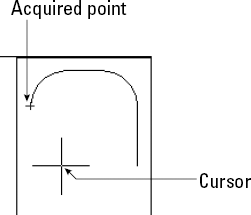
Place the cursor briefly over an object snap, such as the endpoint of a line, to temporarily acquire it. You can acquire more than one point. These acquired points are used to calculate the tracking paths. You see a small plus sign (+) over the object snap as confirmation, as shown in Figure 4.23.
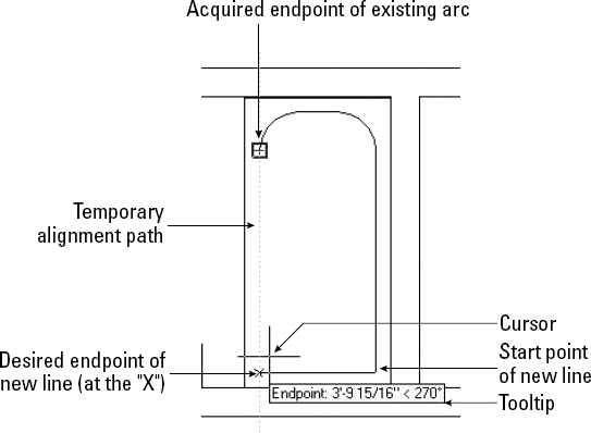
Move the cursor away from the object snap toward your desired point. You see the temporary alignment paths as you move the cursor over available drawing paths, as shown in Figure 4.24. If Ortho Mode is on, you see only horizontal and vertical paths. If Polar mode is on, you see polar paths based on the polar angle settings, as explained earlier in this chapter.
When you see a tooltip and a small x, click it. You can now continue or complete the command, using this point.
After you acquire a point, you can clear it in any one of three ways:
Move the cursor back over the point's plus sign.
Click the Object Snap Tracking button on the status bar to turn it off.
Start any new command.
You can customize the following features of object snap tracking on the Drafting tab of the Options dialog box (choose Application Button
Uncheck Display Polar Tracking Vector to eliminate the tracking paths.
Uncheck Display Full-Screen Tracking Vector to display the tracking paths only from the cursor to the object snap point.
Uncheck Display AutoTrack Tooltip to eliminate the tooltips.
In the Alignment Point Acquisition section, choose Shift to Acquire, which will require you to press Shift to acquire a point when the cursor is over an object snap point.
In the following exercise, you practice locating points with object snap tracking.
Note
The drawing used in the following exercise on locating points with object snap tracking, ab04-c.dwg, is in the Drawings folder on the DVD.
STEPS: Locating Points with Object Snap Tracking
Open
ab04-c.dwgfrom the DVD. Close any palettes that may be open.
Choose Home tab
At the
Specify next point or [Undo]:prompt, pass the cursor overMove the cursor down until it is to the left of
At the
Specify next point or [Undo]:prompt, click atStart the LINE command again. At the
Specify first point:prompt, pick the endpoint of the arc atAt the
Specify next point or [Undo]:prompt, pass the cursor overAt the
Specify next point or [Undo]:prompt, pick the endpoint atChoose Home tab
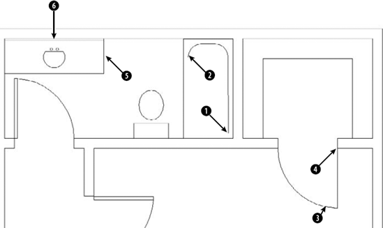
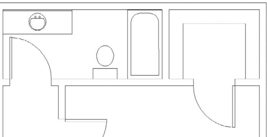
Move the cursor to the middle of the sink, where lines from both midpoints would intersect until you see the tooltip (reading Midpoint: < 270°, Midpoint: < 180°) and click.
At the
Specify radius of circle or [Diameter]:prompt, type 7.5Save your drawing. It should look like Figure 4.26.
The temporary tracking feature is similar to object snap tracking, but limits you to horizontal and vertical directions. Follow these steps:
Start a command.
At a prompt to specify a point, enter tracking
At the
First tracking point:prompt, specify a point (usually using object snaps) that is horizontal or vertical to the final point that you want to specify.Immediately move the cursor horizontally or vertically toward the final point that you want to specify. You see a rubber-band line.
At the
Next point:prompt, move the cursor from the rubber-band line to specify a second point that is also vertical or horizontal to the final point.Press Enter to end tracking and continue the command.
The cursor moves to the intersection of the vertical and horizontal rubber-band lines. You can now continue your command.
Point filters enable you to specify a coordinate by using the X coordinate of one existing object snap and the Y coordinate of another. You construct an X,Y coordinate based on coordinates of existing objects. If this sounds complicated, it is. Object snap tracking should mostly eliminate the need to go back to the old point filter way of doing things. (Point filters have been around for a long time.)
Here's how to use point filters:
Start a command to draw an object.
To specify a coordinate, enter .x or .y
The prompt requests a point. Generally, you specify the point by using an object snap.
The prompt requests the other coordinate value, which you generally provide by using an object snap. (If you're working in 2D, ignore the request for a Z coordinate.)
Continue your command.
Tip
You don't need to use existing coordinates for both the X and Y portions of the coordinate. For example, you can construct an X,Y coordinate by using the Y coordinate of an existing line and picking the X coordinate anywhere on the screen.
The From feature enables you to create a new object starting at a known distance and direction from an existing object. It's like creating one or more invisible lines between the existing object and the new object, helping you to start the new object in the proper place. Use the From feature when the point you need to specify is a known X,Y distance from an object snap but not on any object snap itself. Here's how to use the From feature:
Start a command to draw an object, such as LINE.
Press Shift+right-click, and choose From on the shortcut menu. You can also enter from
The prompt requests a base point, which you usually provide by using an object snap, such as an endpoint.
The prompt requests an Offset, which you provide by using relative or polar coordinates. You can type coordinates or look at the coordinates in the Dynamic Input tooltip or on the status bar and click when you see what you want.
Note
When you specify the offset for the From feature, you need to use the @ symbol to indicate relative coordinates, even if Dynamic Input is set to the default of relative coordinates. The Dynamic Input relative coordinate's setting only applies to the second coordinate that you enter. For example, if you are drawing a line, the first coordinate you enter is considered absolute, and subsequent coordinates are considered relative.
Continue the command you started (in Step 1).
In the following exercise, you practice using the From feature.
Note
The drawing used in the following exercise on using the From feature, ab04-06.dwg, is in the Results folder on the DVD.
STEPS: Using the From Feature
Open
ab04-06.dwg, which you created in an earlier exercise. If you did not do the previous exercise, open the drawing from theResultsfolder of the DVD. Close any palettes that may be open. Make sure Ortho Mode is on and Snap mode is off. Object Snap should be on. Set a running object snap for Endpoint.Save the drawing as
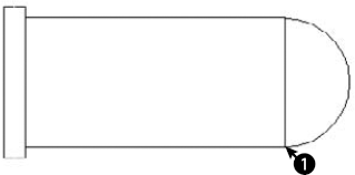
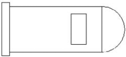
ab04-08.dwgin yourAutoCAD Biblefolder.Choose Home tab
From the Object Snap shortcut menu, choose From.
The prompt asks you for a base point. Pick the endpoint at
At the
<Offset>:prompt, type @−1,0.5You are now ready to continue the line at the
Specify next point or [Undo]:prompt. Press F3 to turn off Object Snap mode. Move the cursor in the 90-degree direction and type 2Move the mouse in the 180-degree direction and type 1
Move the mouse in the 270-degree direction and type 2
Right-click and choose Close from the shortcut menu to close the rectangle and end the LINE command.
Save your drawing. It should look like Figure 4.28.
This chapter covers a great deal about specifying coordinates. These skills form the basis for all your future work with AutoCAD and AutoCAD LT. You read about:
The X,Y coordinate system
Using Dynamic Input
Using absolute Cartesian coordinates
When and how to use relative Cartesian coordinates
Absolute and relative polar coordinates
Direct distance entry
The orthogonal (Ortho) mode
Using polar tracking
Controlling the display of coordinates on the status bar
Grid and PolarSnap settings
Using the visible grid
Using object snaps to specify geometric points on objects
Running object snaps and turning Object Snap mode on and off
Temporarily overriding coordinate settings
Using object snap tracking to locate points
Using point filters to locate points
The From feature for locating points not on an object
The next chapter introduces you to the basics of setting up a drawing.