
Often you may wish that you could zoom in to see a particular part of a drawing more closely or move the display in a certain direction to reveal an area that is hidden. You may also want to save a view so that you can return to it at some other time. In this chapter, you read about controlling the display of your drawing to meet all your drawing needs and increase your productivity. This chapter covers viewing a 2D drawing.
Note
This entire chapter assumes that you're using the 2D Drafting & Annotation workspace and (for AutoCAD) the 2D Wireframe visual style. To check, choose 2D Drafting & Annotation workspace from the Workspace Switching pop-up list on the status bar. To set the visual style to 2D Wireframe, type vscurrent
AutoCAD and AutoCAD LT are vector programs, which means that they store information about objects in your drawing in terms of coordinates and equations. To display your drawing on your computer screen, the programs convert the vector information to pixels. Occasionally, you may need to re-display the objects on your screen. One way is to recalculate the entire drawing, in a process called regenerating (the REGEN command). Another way is to quickly access a virtual screen from your computer's memory; this is called redrawing (the REDRAW command). Keep in mind that redrawing is quicker than regenerating.
When should you use the REDRAW and REGEN commands?
Use the REDRAW command to remove blips or to quickly refresh the screen. (In AutoCAD only, the REDRAWALL command redraws the display in all viewports. Viewports are covered later in this chapter.) To redraw the screen, type redraw

Use the REGEN command whenever you want to recalculate and redisplay the entire drawing. In common usage, the word regen refers to the REGEN command as well as regenerate or regeneration. To regenerate the entire drawing, type regen
Often you cannot see the entire drawing on your screen. You therefore need a way to see the parts of your drawing that are not currently visible.
To pan means to move the display without changing the magnification. The word pan refers to the expression of panning a camera across a scene or view. You pan to view a different part of your drawing.
The PAN command moves the display in the direction and distance that you indicate without changing the magnification. Real-time panning moves the drawing as you move the cursor.
Tip
You can pan past the edge of the screen (actually the viewport). This means that when the cursor reaches the edge of the screen, you can continue moving your mouse in the same direction to continue the pan.
To leave Pan mode, press Esc or Enter, or start any command by using the ribbon, a menu, or toolbar. You can also right-click to open the shortcut menu and choose Exit or one of the other display options. If you pan by using the mouse wheel, you don't need to press Esc or Enter to leave Pan mode.
You can use the scroll bars to pan vertically and horizontally as you would with any Windows program. However, you can't easily predict just how much the drawing view will move. Therefore, the scroll bars are less useful than the PAN command.
Note
You can turn the display of the scroll bars on and off. Choose Application Button
The ZOOM command enables you to zoom in and out of your drawing, like the zoom lens of a camera. When you zoom in, everything is magnified so that you can see it more easily, but you see less of the entire drawing. When you zoom out, objects look smaller, but you can see more of the drawing. The ZOOM command has several options that make it easy to see just what you need at an appropriate size.
Note
Zooming does not affect the actual size of objects. Chapter 9 covers changing the actual size of objects, known as scaling.
Tip
You can zoom past the edge of the screen (actually the viewport). As you move the mouse up or down to zoom, when you reach the edge of the viewport, continue to move the mouse in the same direction to continue the zoom in or out.
You can zoom by rotating the mouse wheel up to zoom in and down to zoom out. There is no Zoom Realtime cursor, and you don't need to press Esc or Enter to leave Zoom mode. You can also double-click the wheel to do a zoom to the extents of the drawing.
Tip
To control how much you zoom for each incremental movement of the wheel, change the ZOOMFACTOR system variable.
The ZOOM command has many options that let you fine-tune the process. Start the command by choosing View tab
Table 8.1. Zoom Options
Button | Option | Description |
|---|---|---|
Previous | Redisplays the most recent display of your drawing. This option has its own button on the status bar. | |
Window | Lets you define a rectangular window as the boundaries of the new display. Use the Window option to zoom in on any area already displayed in your drawing. When you use Zoom Window, the command displays everything in the window that you specify but reshapes the display to fit your screen. As a result, you may see objects that were outside the specified window. You can move the mouse past the drawing area to define the window past the edge of the screen — the display moves to allow you to pick a corner. You don't need to specify this option separately, because the command initially prompts you to specify the first corner of a window. When you do so, you're prompted for the opposite corner. | |
Dynamic | Enables you to zoom and pan in one operation. This option is covered in the following section. | |
Scale | Lets you enter a number to scale the display relative to the drawing limits (a kind of absolute scaling). Enter a number followed by x to scale the display relative to the current view (relative scaling). Enter a number followed by xp to scale the display relative to paper space units (discussed in Chapter 17). A number less than 1 (such as 0.5) reduces the size of the objects on the screen (by half when you use 0.5). A number greater than 1 (such as 2) increases the size of the objects on the screen (to twice the size when you use 2). | |
Center | Lets you specify a new center for the display, and then a new magnification/height. The current magnification/height is shown in brackets for your reference. Type a smaller number to increase the magnification, making the objects larger. Type a larger value to decrease the magnification, making the objects smaller. | |
Object | Lets you zoom in to selected objects. | |
In | Uses the Scale option with a value of 2x. See the Scale option. It's only available from the ribbon drop-down list. | |
Out | Uses the Scale option with a value of 0.5x. See the Scale option. It's only available from the ribbon drop-down list. | |
All | Zooms the display to the greater of the drawing extents or the drawing limits. | |
Extents | Zooms to the outer extents of the drawing. You can also double-click the wheel of your mouse. |
When you use one of the Zoom options, you see the objects in your drawing become larger or smaller in a smooth transition. The smooth transition helps you to orient yourself to the new display. To turn off this feature, use the VTOPTIONS command. In the View Transitions dialog box that opens, uncheck the Enable Animation for Pan & Zoom check box.
Note
When you undo consecutive ZOOM or PAN commands, they count as one operation. Because people often use several ZOOM or PAN operations together, combining them helps you to get back to your previous state more quickly. To disable this feature, choose Application Button
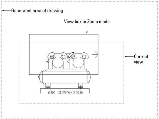
The Dynamic option of ZOOM enables you to pan and zoom in one operation. When you start ZOOM Dynamic, you see the virtual screen area of the drawing in a blue, dashed rectangle; this view box represents the drawing extents or limits, whichever is greater. Your current view is bounded in a green, dashed rectangle. Your mouse cursor changes, based on the two modes of ZOOM Dynamic. Each time you click the left mouse button, you switch modes. Here's how the two modes work:
Pan mode. The view box contains an X and can move freely around any displayed area of the drawing.
Zoom mode. The view box contains an arrow. The left side of the box is fixed at the point where you changed to Zoom mode. As you move the cursor, the box expands or shrinks, letting you zoom to any magnification.
When the view box displays the view that you want, click the right mouse button and choose Enter (or press Enter). The command pans and zooms to show that view. Figure 8.1 shows the screen during a ZOOM Dynamic operation.
Note
The drawing used in the following exercise on panning and zooming, ab08-a.dwg, is in the Drawings folder on the DVD.
STEPS: Panning and Zooming
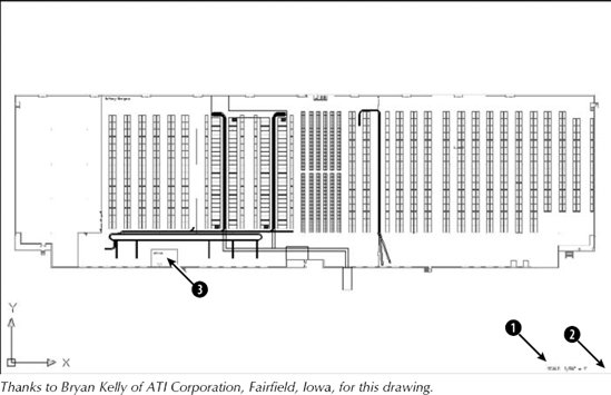
Open
ab08-a.dwgfrom the DVD. This is a drawing of a warehouse, as shown in Figure 8.2.
At the
Specify corner of window, enter a scale factor (nX or nXP), or [All/Center/Dynamic/Extents/Previous/Scale/Window/Object] <real time>:prompt, pick


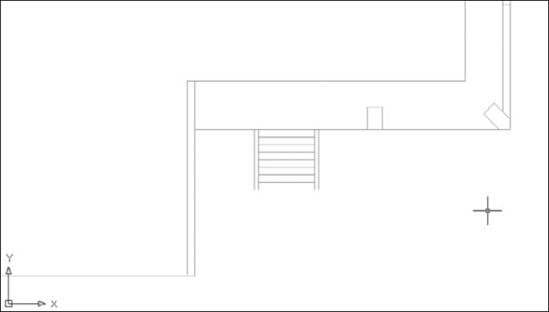
You are now in Zoom mode. The Zoom box contains an arrow. Move the mouse to the left to shrink the Zoom box. Notice that the Zoom box is fixed at its left side. When the Zoom box is about half of its original size, left-click again.
You are back in Pan mode again. Move the Pan box to the bottom-right corner of the warehouse. Right-click and choose Enter to zoom in on this new view. Your display should look approximately like Figure 8.3.

The SteeringWheel is a navigation device that allows you to zoom and pan from a single interface. It also lets you rewind through previous displays. This wheel is an all-in-one navigation tool for both 2D and 3D use. For more information on 3D navigation, see Chapter 22. In AutoCAD LT, the wheel offers only 2D navigation tools. Figure 8.4 shows the 3D Navigation SteeringWheels.
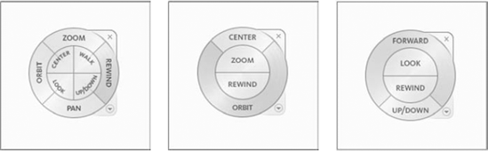
Figure 8.4. The SteeringWheel is a quick navigation device that hovers at the cursor. It comes in several configurations.
Pan. Place the cursor over the Pan wedge, click and hold the pick button, and drag in the direction you want to pan. When you click, you immediately see the Pan cursor.
Zoom. Place the cursor over the Zoom wedge, and then click and hold the pick button. Drag up or to the right to zoom in. Drag down or to the left to zoom out. When you click, you immediately see the Zoom cursor.
Rewind. Click and hold the Rewind wedge. You see a series of windows showing each view that you've displayed. Drag over the windows and release the mouse when you see the view that you want.
Orbit. Click and hold the Orbit wedge to view your drawing in various 3D views. I discuss Orbit in Chapter 22 (AutoCAD only).
Center. Click a pivot point for 3D navigation. I discuss this feature more in Chapter 22 (AutoCAD only).
Walk. Lets you walk through a 3D drawing. I discuss walking through a drawing in Chapter 22 (AutoCAD only).
Look. Swivels the 3D view. I discuss this further in Chapter 22 (AutoCAD only).
Up.Down. Moves the view along the Y axis, like going up or down in an elevator. I discuss this further in Chapter 22 (AutoCAD only).
To exit, Press Esc or Enter or click the wheel's X button. To configure the wheel, right-click and choose SteeringWheel Settings. In the SteeringWheel Settings dialog box, you can configure both 2D and 3D features. For example, you can change the wheel's size and opacity, and display a mini wheel, which is a smaller version of the SteeringWheel. You can also quickly choose one of the configurations from the shortcut menu. The SteeringWheel Settings dialog box and option are in AutoCAD only.
After you've done a lot of panning and zooming in a drawing, you may find that you return to the same part of your drawing again and again, especially if the drawing undergoes a lot of changes. In a large drawing, it can take some time to display the part of the drawing that you want. You can speed up the process by saving views.
A view is simply a display of a drawing on your screen. A view can show any part of your drawing at any magnification. After you have the display that you want, you give the view a name and then save it. AutoCAD or AutoCAD LT then lets you retrieve that view at any time, without zooming or panning.
First display the view that you want to save on the screen. Then choose View tab
The Views pane lists the following types of views:
Current. The current display.
Model views. All named views, including cameras, in model space. Model space is where you draw. I cover the concept of model space in Chapter 17. Cameras are a way to define 3D views (they are not available in AutoCAD LT); I explain cameras in Chapter 22.
Layout views. All named views created in a layout (paper space). A layout is a mechanism for laying out your drawing in preparation for plotting or printing. I explain layouts in Chapter 17.
Preset views. Preset views that come with AutoCAD and AutoCAD LT. These are the same views that you see by choosing View tab

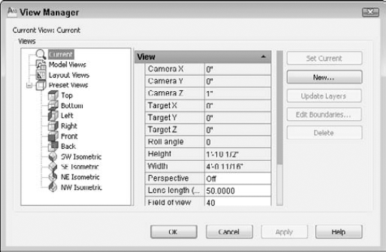
When you choose a view in the Views panel, you see its properties in the central panel of the View Manager dialog box. The available properties depend on the type of view. You can use the properties panel to change most of a view's properties; some are for information only and are not editable. Some of the properties only apply to 3D views, and some are not available in AutoCAD LT. Table 8.2 lists the properties that may appear in the View Manager.
Table 8.2. View Properties
Property | Description |
|---|---|
Name | Named Views, Cameras, and Layout Views |
Category | The category that you specify when you create a new named view. A category is optional and applies only to model and layout views. If you specify a category, it appears on the Sheet Views tab of the Sheet Set Manager (covered in Chapter 26). |
Specifies whether the view is associated with a viewport on a sheet in a sheet set. This applies only to layout views. | |
UCS | The name of the User Coordinate System (UCS) saved with the view. When you create a named view, you can save a UCS with that view. I cover UCSs later in this chapter. |
Layer snapshot | Specifies whether the current layer states are saved with the view. You can save this layer snapshot with a model or layout view. I cover layer states in Chapter 11. |
Location | Specifies the layout tab name when you define a named view on a layout tab. See Chapter 17 for a discussion of layout tabs. |
Annotation Scale | Stores the annotation scale that was current when you defined the view. See Chapter 17 for more on annotation scales. |
Visual style | Specifies a visual style for the view. This applies only to model views. I explain visual styles in Chapter 22; they apply mostly to 3D drawings. For 2D drawings, the visual style is 2D Wireframe. |
Background | Specifies a background for the view. Backgrounds apply only to 3D model views (AutoCAD LT does not offer backgrounds). Choose Solid, Gradient, Image, or Sun & Sky to open the Background dialog box. I cover backgrounds more in Chapter 22. |
Live section | Specifies a live section object applied to the view. See Chapter 24 for more on live sections. |
View type | Displays the type of shot, used for animation and playbacks. I discuss creating animated presentations (the ShowMotion feature) later in this chapter. |
Transition type | Displays the type of transition between views, when shown as an animated presentation (the ShowMotion feature). |
Transition duration | Displays the length of the transition between shots. |
Playback duration | Displays the length of the display of the shot, when played back as an animated presentation. |
Camera X | Displays the X coordinate of the view's camera. This is for information only and does not apply to layout views. |
Camera Y | Displays the Y coordinate of the view's camera. This is for information only and does not apply to layout views. |
Camera Z | Displays the Z coordinate of the view's camera. This is for information only and does not apply to layout views. |
Target X | Displays the X coordinate of the view's target. This is for information only and does not apply to layout views. |
Target Y | Displays the Y coordinate of the view's target. This is for information only and does not apply to layout views. |
Target Z | Displays the Z coordinate of the view's target. This is for information only and does not apply to layout views. |
Roll angle | Specifies the angle that the view is tilted around the line of site. This is for information only and does not apply to layout views. |
Height | Specifies the height of the view. This is for information only and does not apply to camera views. |
Width | Specifies the width of the view. This is for information only and does not apply to camera views. |
Specifies whether a view is a perspective view. This applies to model views. I discuss perspective views in Chapter 22. | |
Lens length (mm) | Specifies the lens length in millimeters. This applies to perspective views only. The LENSLENGTH system variable controls the default value for this setting. Changing this value also changes the Field of View setting, which is another way of expressing this setting. |
Field of view | Specifies the field of view of a perspective view. Changing this value also changes the Lens Length setting. This does not apply to layout views. |
Front plane | Specifies the offset for the front clipping plane if you enabled front clipping. I cover clipping in Chapter 22; it applies to 3D views only. |
Back plane | Specifies the offset for the back clipping plane if you enabled back clipping. |
Clipping | Turns clipping on or off. |
To create a new named view, click New to open the New View / Shot Properties (or New View in AutoCAD LT) dialog box, as shown in Figure 8.6. Type a name for your view in the View Name text box. To specify a view, you use the View Properties tab in AutoCAD.
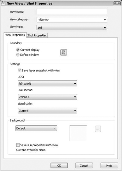
View names can be up to 255 characters and can include spaces. As explained in Table 8.2, you can save a category, a layer snapshot, a User Coordinate System, a live section, and a visual style with a view. Select the Current Display option button to use the current display as the view. Otherwise, click the Define View Window button, and specify a window around the view that you want. Press Enter to return to the New View / Shot Properties (New View in AutoCAD LT) dialog box.
Click New again to define another new view, or choose OK to return to the View Manager dialog box, where you see your new view listed. Click OK to return to your drawing.
Tip
In a very large drawing, you might create views as soon as you create the titleblock — for example, one for each quadrant of the drawing and another for the titleblock lettering. This helps you move quickly from one section of the drawing to another. As you determine the need for more specific views, you can add them.
The View Manager enables you to easily display any view that you have saved. Follow these steps:
Choose View tab
Choose the view that you want to restore.
Click Set Current.
Click OK.
You can use the View Manager to manage named views. You can also find these features by right-clicking inside the View Manager.
To delete a view, choose the view that you want to delete and click the Delete button or press the Delete key on your keyboard.
To rename a view, select it, type a new name in the Properties pane (next to the Name property), and press Enter.
To change the layer states that you saved with the view, change the states of any layers before opening the dialog box. Then open the View Manager dialog box, choose a named view, and click Update Layers. The view now uses the current layer states. (I explain layers in Chapter 11.)
To edit the boundaries of a view, choose the Edit Boundaries button. You are now back in your drawing and the current view boundaries are shown in black or white (depending on the color of your background). At the prompts, specify the two opposite corners that you want to serves as boundaries for the view and press Enter.
You can create a presentation that displays one named view after another, as a way to show the drawing, perhaps to a client or colleague. In essence, you create a slide show from named views in your drawing. Each view can have a transition, as well as timing for the transition and the display of the view itself; together, these properties are called a shot. A looping feature lets you create an ongoing display of views. This feature, called ShowMotion, is not available in AutoCAD LT. You define the shot on the Shot Properties tab of the New View / Shot Properties dialog box, as shown in Figure 8.7.
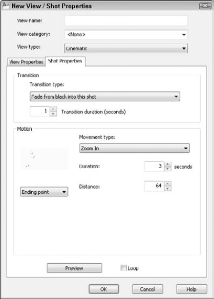
Figure 8.7. Use the Shot Properties tab of the New View / Shot Properties dialog box to create and configure a presentation of your drawing.
To configure the shot, first choose one of the view types:
Cinematic. Allows you to choose a movement for the view. Most of the options are appropriate for 3D drawings only. The options are Zoom In, Zoom Out, Track Left, Track Right, Crank Up, Crank Down, Look, and Orbit. Each movement has its own settings. Try them out and click the Preview button to see what they look like.
Still. Displays a still view. You can specify the duration of the view.
Recorded Walk. Lets you record a walk-through of a 3D model. I discuss this feature in Chapter 22.
Next, choose a transition from the Transition Type drop-down list. Then enter a duration for the transition in the Transition Duration text box. Finally, use the Duration text box to specify how long the view displays. Click OK when you're done.
Tip
The Fade from Black into This Shot looks best with a black background. The Fade from White into This Shot looks best with a white background. See Appendix A for instructions on changing the background color of the drawing area.
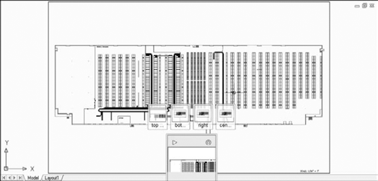
Use the navigation tools to do the following:
Click any view to display that view.


To edit the properties of a shot, right-click the thumbnail of an individual shot and choose Properties, or use the EDITSHOT command and enter the name of the shot. The View / Shot Properties dialog box opens, where you can change the settings of the shot.
Note
The drawing used in the following exercise on working with views, ab08-a.dwg, is in the Drawings folder on the DVD.
Open
ab08-a.dwgfrom the DVD if it is not already open from the previous exercise.Save the file as
ab08-01.dwgin yourAutoCAD Biblefolder.Choose View tab
Click New to open the New View / Shot Properties (New View in AutoCAD LT) dialog box, with the View Properties tab on top if you are using AutoCAD.
In the View Name text box, type top left.
Click the Define Window option button or the Define View Window button to return to your drawing temporarily.
At the
Specify first corner:prompt, pick the top-left corner of the drawing. At theSpecify opposite corner:prompt, pick somewhere around the center of the warehouse. Press Enter to return to the New View / Shot Properties (New View in AutoCAD LT) dialog box.If you are using AutoCAD LT, go to the next step. Click the Shot Properties tab. Check that the View type is set to Still. Change the Transition Duration to 0.5 seconds. In the Motion section, change the Duration to 1 second.
Click OK once.
Click New again. Type bottom left in the text box of the New View / Shot Properties (or New View in AutoCAD LT) dialog box.
Click the Define View Window button. At
the Specify first corner:prompt, pick the bottom-left corner of the drawing. At theSpecify Opposite corner:prompt, again pick around the center of the warehouse. Press Enter.If you are using AutoCAD LT, go to the next step. Click the Shot Properties tab. Again, change the Transition Duration to 0.5 seconds. In the Motion section, change the Duration to 1 second, as you did previously.
Click OK. The View Manager dialog box should list both of your views. Click OK to close the View Manager.
Choose View tab

Save your drawing. The views that you created are now part of the drawing database.
Using named views provides three additional advantages:
You can use named views when you open a drawing so that one of its views is immediately displayed.
You can open only the part of a drawing contained in a view.
You can turn a named view into a floating viewport for plotting purposes (AutoCAD only).
I explain these techniques in the next three sections.
After you've saved views, you can use them to open a drawing so that a view is immediately displayed. Click Open on the Quick Access toolbar. In the Select File dialog box, choose the file that you want to open and check the Select Initial View check box. Then click Open. In the Select Initial View dialog box, choose the view that you want to display, and click OK.
You may have a very large drawing that is slow and cumbersome to work with when it is completely loaded. For example, if you have a surveyor's drawing of an entire county, but you need to work only with one plat, you can open a named view containing only that plat. This feature is not available in AutoCAD LT.
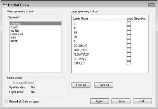
To partially open a drawing from within AutoCAD, follow these steps:
Click Open on the Quick Access toolbar to open the Select File dialog box.
Choose a drawing and then click the Open button's drop-down list. Choose Partial Open to open the Partial Open dialog box, as shown in Figure 8.9.
Choose a view from the list of named views.
Check the check box of one or more layers. To include all the layers, click Load All. If you don't include at least one layer, no objects are loaded. (Chapter 11 covers layers.) Click Open.
After you've partially opened a drawing, you can load more of the drawing. Enter partiaload
You can combine layouts from more than one drawing into a sheet set. (AutoCAD LT doesn't include this feature.) Sheet sets are a powerful way to organize many layouts. I cover them in detail in Chapter 26. However, at this point you should know that named views have a value beyond helping you display an area of your drawing. They can become your final layout for plotting.
Suppose that you're drawing a mechanical model with a top view, a side view, and a section view. In the final plot, you want to display these three views on one sheet of paper. Without sheet sets, you would create three floating viewports and individually pan and zoom to get the three views. (For more information on floating viewports, see the "Floating viewports" sidebar in this chapter, as well as Chapter 17.) Using the sheet-set feature as you work, you can create named views of the three parts of the drawing. Then you can use those same views to create the floating viewports for plotting.
Tiled viewports enable you to divide up the screen into rectangular bounding boxes. You can then show different views of your drawing in each viewport — at one time. The purpose of tiled viewports is to help you draw. For example:
You can see the whole drawing in one viewport and a zoomed-in portion of that drawing in another viewport.
You can see widely separated views of a large drawing at one time.
Note
There are two types of viewports — tiled and floating. For more information on floating viewports, see the "Floating viewports" sidebar in this chapter. For a detailed discussion, turn to Chapter 17.
Actually, you're already using a tiled viewport, because the regular single view of your drawing that you've been working with represents the default of a one-tile viewport. Tiled viewports have the following characteristics:
No matter how many viewports you have, they always collectively take up the entire screen. They are not separate entities but a way of dividing the screen.
Only one viewport can be active at a time. The active viewport has a bold border.
The crosshairs appear only in the active viewport.
The UCS (User Coordinate System) icon (if set to On) appears in each viewport.
Any change that you make to your drawing in one viewport automatically appears in every other viewport (or in viewports that show the part of the drawing where you made the change).
You can create up to 64 viewports — but you'll never want to create that many!
You can begin a command in one viewport and finish it in another. For example, you can start a line in one viewport, switch to a second viewport, and end the line there.
You can save and restore viewport configurations.
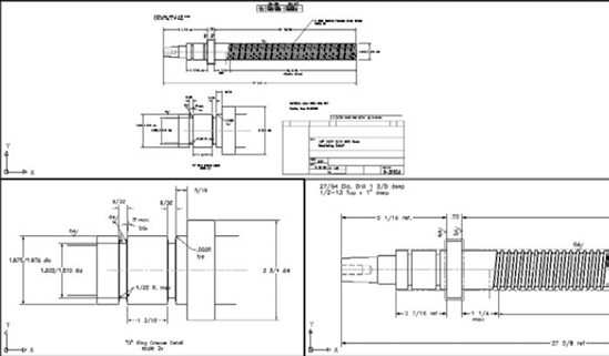
Figure 8.10 shows a drawing divided into three tiled viewports. Each viewport shows a different view of the same drawing.
Creating tiled viewports involves deciding how you want to divide up the screen. A set of tiled viewports is called a configuration. A few simple configurations come with AutoCAD and AutoCAD LT, but you can create your own by further dividing up any of the viewports. You can also join two adjacent viewports. Finally, you can always return to the default of one viewport.
If you have named views in your drawing, you can specify a view for each viewport to display. Click a viewport in the Preview pane and choose a named view from the Change View To drop-down list at the bottom of the dialog box. You can also choose a visual style from the Visual Style drop-down list if you are using AutoCAD. If your drawing is in 3D, you can choose 3D from the Setup drop-down list, and AutoCAD creates standard orthogonal views in the viewports. When you've specified your viewport configuration, click OK to return to your drawing.
The Viewports dialog box is usually the best place to start creating viewports. However, if the standard configurations do not meet your needs, you can use one of them as a starting point and then use the other options.
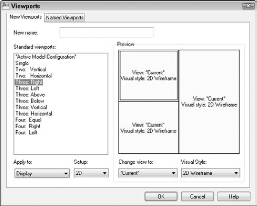
Notice the Apply To drop-down list at the bottom-left corner of the Viewports dialog box in Figure 8.11. By default, the tiled viewport configurations apply to the entire display, meaning that they replace your current configuration. You can also choose to apply the configuration to the viewport that is currently displayed in the drawing area. The active viewport has a bold border and crosshairs. To make a viewport active, click anywhere inside that viewport. Then choose View tab
Let's say that you have four equal viewports, and the top-left viewport is active. If you choose the Four: Equal configuration from the Viewports dialog box while the top-left viewport is active and apply it to the current viewport, the top-left viewport is divided into four viewports. Now you have seven viewports in the drawing.
After you've created the viewport configuration that you want, the first step is to create the views that you need in each viewport. Just click in a viewport, and zoom and pan until you have the view that you want.
Tip
Many users choose one viewport to display the entire drawing and the other viewports to display zoomed-in views of smaller sections.
One of the great advantages of viewports is that you can draw from one viewport to another. In a large drawing, you may need to draw a line from one end of the drawing to another, but when you display the entire drawing, you can't see the detail well enough to specify where to start and end the line. To draw from one viewport to another, just click the viewport where you want to start. Start a command, specifying any necessary coordinates. To continue the command in a second viewport, click to activate that viewport. Continue the command, specifying coordinates as necessary.
You can also use viewports to edit your drawing. All commands except those that change the display — such as zooming, panning, and creating views — can be started in one viewport and continued in another.
You can save a tiled viewport configuration. Then you can restore it when needed. Viewport configuration names can be up to 255 characters and can include spaces.
After you create a viewport configuration that you like, choose View tab
After returning to one viewport or using a different configuration, you can restore a named viewport configuration. Choose View tab
Note
The drawing used in the following exercise on creating, naming, and restoring tiled viewport configurations, ab08-b.dwg, is in the Drawings folder on the DVD.
STEPS: Creating, Naming, and Restoring Tiled Viewport Configurations
Open
ab08-b.dwgfrom the DVD.Save the file as
ab08-02.dwgin yourAutoCAD Biblefolder.
In the listing at the left of the dialog box, choose Three: Above. Click OK. You see three tiled viewports.
Click the bottom-right viewport. Choose Zoom on the status bar and choose a window around the left portion of the threaded model (the upper part of the drawing).
Click the bottom-left viewport. Again choose Zoom on the status bar and choose a window around the bottom-left portion of the drawing (not including the titleblock).
Click the top viewport. Choose View tab
Choose View tab
With the top viewport still active, choose View tab
Choose View tab
Choose
3 view O Ringand click OK to restore the viewport configuration, including the views in each viewport.Save your drawing.
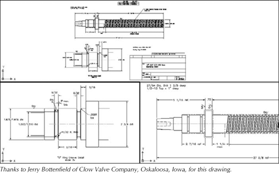
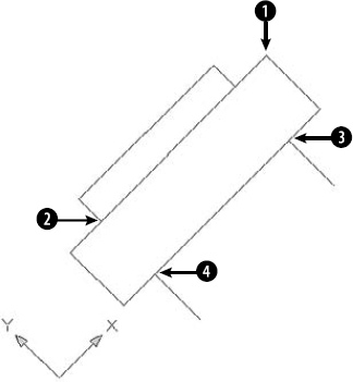
Not all 2D drawings are vertical and horizontal. In some drawings, significant portions of your objects need to be at nonorthogonal angles. One example is an auxiliary view to show the "true size" of an inclined surface. Sometimes it helps to rotate the crosshairs to match the major angles of the drawing.
Consider Figure 8.13. A great deal of this drawing is at an angle. You could handle this in four ways:
Draw as normal, specifying the necessary angles.
Rotate the snap, which also rotates the grid and crosshairs.
Create a new User Coordinate System (UCS). (Creating a new UCS is covered later in this chapter.)
Draw the entire model vertically and rotate it afterward.
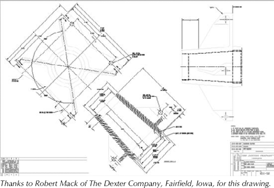
Figure 8.13. In 2D drawings such as this, you should consider various options, such as rotating the snap or creating a new UCS.
If you need to draw several objects at a certain angle, such as 45 degrees, you can rotate the snap to that angle. The grid and crosshairs rotate to follow suit. This technique works best when the decimal point accuracy required lets you draw by using snap points. You can also use this technique to guide the cursor at an appropriate angle for direct distance entry, although polar tracking is another way to accomplish the same task.
To change the snap rotation angle, you use the SNAPANG system variable. Enter snapang
Note that you can also set an X base and a Y base. This simply ensures that the grid goes through a point of your choice, which is very important if you're using Snap mode to draw. If you're just starting to draw an object, use the 0,0 base and draw to the existing snap points. However, if you have an existing object and need to add to it, changing the base can be very helpful. Setting X and Y bases does not change the coordinates, which are tied to the UCS. (The UCS is discussed in the next section.) To set the base, use the SNAPBASE system variable on the command line and specify a coordinate for the base. You can use an object snap.
Note
You can use the ID command to get the coordinates of a point. Then use these coordinates as the X and Y bases. Chapter 12 covers the ID command.
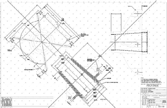
After setting the snap angle, you may want to turn the grid on to help you get your bearings. The crosshairs and grid now reflect the new snap angle. Figure 8.14 shows the same drawing with a snap angle of 45 degrees. Notice how the crosshairs now match the angle of the drawing. The crosshairs have been set to 100 percent of screen size, which is useful when rotating the snap angle. (To reset the crosshairs size, choose Application Button
You can create a new User Coordinate System (UCS) rather than rotate the snap angle. The results are similar, except that when you create a UCS, you also affect the X,Y coordinates. The UCS is much more flexible when you start drawing in three dimensions.
By default, a drawing is set up by using a World Coordinate System. This sets the origin of the X,Y points at 0,0 and the angles using the familiar East (right-facing) equals 0 degrees system. Figure 8.15 shows the UCS icon in its default display.

You can easily create your own UCS and even save it for future use in the drawing. To define a UCS in a 2D drawing, you indicate the angle of the X and Y axes and an origin point. The origin point then becomes the new 0,0 coordinate. You have several options for specifying the UCS.
Understanding the UCS options will help you create a new UCS more easily, based on the information that you have available. To create a UCS, choose View tab
Table 8.3. UCS Options
Button | Option | Meaning |
|---|---|---|
World | Specifies the default UCS, with the X axis horizontal, the Y axis vertical, and the origin at the initial 0,0 location. | |
Origin | Specifies a new 0,0 point of your choice, relative to the current origin. | |
View | Aligns the X and Y axes with the current view. Used in 3D drawing. This option arbitrarily sets the origin. | |
X | Keeps the current origin and rotates the Y and Z axes around the current X axis. You specify the angle. This is used in 3D drawing. | |
Y | Keeps the current origin and rotates the X and Z axes around the current Y axis. You specify the angle. This is used in 3D drawing. | |
Z | Keeps the current origin and rotates the X and Y axes around the current Z axis. You specify the angle. This option can be used in 2D drawing. | |
Object | Enables you to align the UCS with an object. In general, this option uses the most obvious object snap as the origin and aligns the X axis with the object. For example, when you choose a line, the endpoint nearest your pick point becomes the origin and the X axis aligns with the angle of the line. When you choose a circle, the X axis points toward the point that you pick on the circumference. | |
Z-Axis Vector | Specifies which way the Z axis points. This option is not used in 2D drawing. | |
Face | Aligns the UCS with the face of a 3D solid. | |
3 Point | Enables you to specify three points. The first point is the origin, the second point indicates the positive direction of the X axis, and the third point indicates the positive direction of the Y axis. |
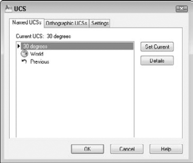
After you create a UCS, you can save it so that you can easily switch back and forth between the World Coordinate System and your UCS. To save a UCS, follow these steps:
Specify the UCS as described in the previous section.

Click
Unnamed. Type a name for the UCS and press Enter. The name can be up to 255 characters and can include spaces.Click OK.
To restore a saved UCS, return to the same dialog box, choose the UCS that you want to use, and click Set Current. To delete a saved UCS, select it in the UCS dialog box and press the Del key. You can also select a UCS, right-click, and choose one of the options from the shortcut menu. When you're done, click OK to close the dialog box.
When you start a new drawing, the UCS icon is at the bottom left of your drawing at 0,0. By default, the icon remains at 0,0 even if you pan around the drawing. The icon may, therefore, end up in the middle of your drawing. If 0,0 is off the screen, then the icon reverts to the bottom left of your drawing.
You can turn off the UCS icon completely. If you aren't working with customized UCSs, you often have no reason to see the UCS in a 2D drawing. If you want the UCS icon on, you can also display it only at the bottom left of your drawing. This keeps the icon out of the way so that it does not obstruct your drawing.
If you create a new UCS, keeping the UCS icon at the 0,0 point (the origin) of your new UCS helps you to get your bearings. A plus sign appears in the icon to indicate the origin. However, if the origin is out of the current display or so close to the edge that the icon won't fit, the UCS icon appears at the lower-left corner of your drawing anyway.
To control the UCS icon, choose View tab
On. Toggles the display of the UCS icon on and off. You can also turn the display on and off by choosing View tab
Display at UCS Origin Point. Toggles the placement of the UCS icon at the origin on and off.
Apply to All Active Viewports. Applies the preceding two settings to all viewports, rather than to just the current viewport.
You can customize the look of the UCS icon. To do this, choose View tab
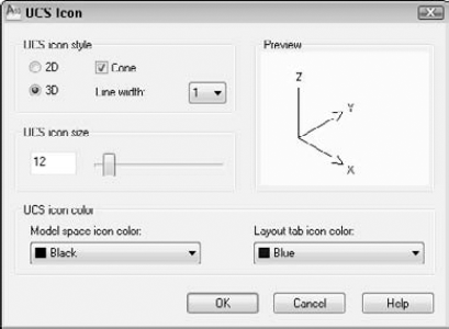
Choose between 2D and 3D styles. The 3D style shows the Z axis, but you won't see it when you're looking at your model from the top (called Plan view). If you choose the 3D style, you can check the Cone box to display a cone effect for the arrows of the X and Y axes. Either way, the Z axis has no arrow, which enables you to distinguish it from the X and Y axes. You can also choose a line width from 1 to 3, 1 being the default.
You can change the size of the icon. Just drag the slider up and down to get the result you like. Finally, you can change the color of the icon, both in model space and in paper space layouts. (I cover paper space layouts in Chapter 17.) Click OK to close the dialog box.
In this exercise, you practice drawing with a custom UCS to create the basic framework for the drawing shown previously in Figures 8.13 and 8.14, a bearing housing for a commercial dryer.
Note
The drawing used in the following exercise on drawing with a custom UCS, ab08-c.dwg, is in the Drawings folder on the DVD.
STEPS: Drawing with a Custom UCS
Open
ab08-c.dwgfrom the DVD. This exercise assumes that you have Dynamic Input on, with the default relative coordinates setting.Save the file as
ab08-03.dwgin yourAutoCAD Biblefolder. Ortho Mode and Object Snap should be on. Set a running object snap for Endpoints only.
At the
Specify rotation angle about Z axis <90>:prompt, type 45Choose Home tab
Choose Home tab
Start the LINE command again. Follow the prompts:
Specify first point:
Choose the From object snap. Base point:Use the Endpoint object snap to pick pointin Figure 8. 19. <Offset>:Type@-.875,0Specify next point or [Undo]:Move the cursor in the 90° direction (which looks like the 135° direction because of the rotated UCS)..625Specify next point or [Undo]:Move the cursor in the 180° direction.3.75Specify next point or [Close/Undo]:Move the cursor in the 270° direction..625Specify next point or [Close/Undo]:Start the LINE command again.
Turn on Object Snap Tracking on the status bar and follow the prompts:
Specify first point:
Pass the cursor over
and then over
in Figure 8.18 to acquire these points. Move the cursor to
at the intersection of the two temporary tracking lines and click.Specify next point or [Undo]:
Move the cursor in the 270° direction relative to the UCS.1.25. Specify next point or [Undo]:Because you would normally continue working on this drawing, you should save the UCS. Choose View tab
Still in the dialog box, choose World, click Set Current, and click OK to return to your drawing. The UCS icon and crosshairs return to their familiar angle.
To return to the Rotated 45 UCS, again open the UCS dialog box with the Named UCSs tab on top. Choose Rotated 45 and click Set Current. Click OK to restore the Rotated 45 UCS.
Save your drawing.
Tip
After creating a new, rotated UCS such as the one in the previous exercise, type plan (to start the PLAN command) and use the Current UCS option to remove the rotation. Now you aren't working at an angle in your UCS. To return to the World UCS, type plan again and choose the World option to return to your drawing's previous state.
An isometric drawing is a 2D drawing made to look like a 3D drawing. Every child learns how to draw a box that looks three dimensional. By drawing parallelograms instead of squares, the drawing gives the impression of being in three dimensions. AutoCAD and AutoCAD LT enable you to do the same thing. However, most people use true 3D tools these days. For more information, see Part IV of this book.
The ISOPLANE (short for isometric plane) command rotates the crosshairs to the special angles required for isometric drawing. You then toggle the ISOPLANE setting from left to right to top, to draw on each of the three "planes." As you do so, the angles of the crosshairs, snap, and grid change to the appropriate angles.
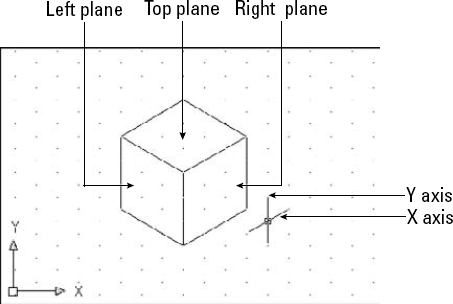
These angles are 30 degrees for the X axis, 90 degrees for the Z axis, and 150 degrees for the Y axis. As you toggle among the planes, you see the crosshairs take on various configurations of these angles. Figure 8.19 shows the standard isometric cube. You can see three sides — left, right, and top. In the figure, the crosshairs are set to the right isometric plane.
Isometric drawing is not often used for precise drawing because specifying the exact points that you need can be difficult. Also, true 3D drawing has mostly supplanted isometric drawing. Isometric drawings are sometimes still used for piping work as well as for illustrations.
Tip
Use snap points and object snaps as much as possible in an isometric drawing. Also, you can enlarge crosshairs to better visualize the isometric planes. (Choose Application Button
To start Isometric mode, right-click the Snap button on the status bar and choose Settings to open the Drafting Settings dialog box. On the Snap and Grid tab, in the Snap Type section, choose Grid Snap (if it is not already selected), and then Isometric Snap to enter Isometric mode. While you're there, turn on Snap and Grid if you want them on. Click OK. After you're in Isometric mode, press F5 to toggle from plane to plane.
Drawing lines in Isometric mode is fairly straightforward if the lines are parallel to one of the isometric plane angles. Circles and arcs in Isometric mode must be drawn as ellipses and elliptical arcs. When you're in Isometric mode, the ELLIPSE command has an Isocircle option.
Tip
Polar coordinate display is very helpful while drawing isometrically. The coordinates are easier to understand than the unusual absolute snap point coordinates created by ISOPLANE.
In this chapter, you read how to control the display of your drawing. You learned about:
The PAN and ZOOM commands, including real-time pan and zoom and the many ZOOM options
Using the SteeringWheel
Saving several views of your drawing so that you can retrieve them quickly
Creating animated presentations of your drawing
Creating tiled viewports for drawing and editing, as well as naming and displaying useful viewport configurations
Rotating the snap and grid
Creating a User Coordinate System, saving a UCS, and then setting it as current
Setting the snap style to isometric to create isometric drawings
In the next chapter, you discover how to start editing your drawings.