
In Chapter 14, you drew many dimensions using the default dimension style. However, you can create your own dimension styles to control the way dimensions appear. Now that you're familiar with dimensions, you can learn how to customize them to suit your needs.
You should create your dimension styles before dimensioning. Some drawings have several dimension styles, although a drawing can look confusing if it has too many dimension styles. In general, you create a dimension style, save it in your template drawings, and (you hope) rarely have to deal with it again, except to override a setting for a unique situation.
The various disciplines each have their own standards and customs regarding dimensions. Dimension styles are flexible enough to accommodate any type of dimensioning practice.
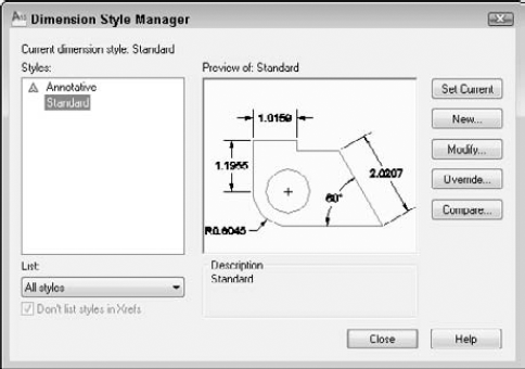
The Dimension Style Manager is the master control room for managing dimensions. Here you create new dimension styles and modify existing ones.
The preset Standard dimension style is most appropriate for mechanical drafting. Whichever type of drafting you do, you'll probably need to make some changes to the default dimension style or create a new dimension style. A preview of the current dimension style is shown at the right side of the dialog box.
To create a new style, click New to open the Create New Dimension Style dialog box, as shown in Figure 15.2. Type a new name in the New Style Name text box. In the Start With drop-down list, choose which existing dimension style you want to use as a basis for the new dimension style. If you have more than one to choose from, choose the style that most resembles the new style you want to create.
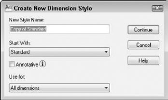
If you want dimensions that use this dimension style to be annotative, check the Annotative check box. Annotative dimensions are valuable when you will be displaying your model at more than one scale, in separate viewports.
Note
Annotative objects automatically scale according to the scale of a viewport on a layout. You use a layout to lay out a drawing for plotting, and viewports display various views of the drawing. Each viewport can have a different scale, and annotative objects automatically adjust in size accordingly. I discuss annotative objects more in Chapter 17.
The Use For drop-down list lets you decide whether you want to use the dimension style for all dimensions or only for a specific type of dimension; you can choose from Linear, Angular, Radius, Diameter, Ordinate, or Leaders and Tolerances. Usually, you create a dimension style for all dimension types. Later in this chapter, I explain how to create variants of dimension styles for specific types of dimensions. When you're done, click Continue.
You can also use the Dimension Style Manager to rename an existing dimension style. Click its name to select it. Click it a second time to see an edit box. Type the new name and press Enter.
Dimension styles have many components, and so the process of defining a dimension style is complex. Your task is organized for you by the tabs of the dialog box.
When you click Continue in the Create New Dimension Style dialog box, a second New Dimension Style dialog box opens, as shown in Figure 15.3.
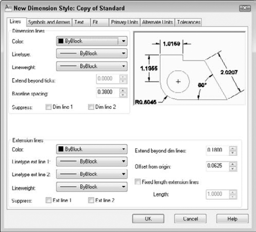
An important part of defining a dimension style is specifying how the dimension lines and extension lines look, which you do on the Lines tab of the New Dimension Style dialog box. In Chapter 14, I illustrate the parts of a dimension. Refer to Figure 14.1, if necessary.
To set the color of the dimension line so that it differs from that of the rest of the dimension, click the Color drop-down list and choose a color. Choose Select Color to open the Select Color dialog box if you want to use a nonstandard color. Remember, a dimension is a block — that is, it is one object. The default color is ByBlock so that dimensions take on the color of the current layer or color setting. In general, you should have a separate layer for dimensions so that the entire dimension is the color set for that layer. Use this setting only if you want the dimension lines to be a different color from your dimension layer color. The arrowheads do not have a separate color setting and always follow the dimension-line setting.
Note
See Chapter 11 for a discussion of how to use the Select Color dialog box. See Chapter 18 for coverage of blocks.
To specify a linetype for a dimension, choose one from the Linetype drop-down list. If the linetype that you want isn't on the list, then you need to load it. To do this, choose Other to open the Select Linetype dialog box. (For more information on loading linetypes, see Chapter 11.) The default lineweight is ByBlock, which means that it takes on the lineweight of the current layer. To set a lineweight for the dimension line, click the Lineweight drop-down list and choose a lineweight. In general, you want your objects to stand out, so dimensions should have a lineweight the same as, or narrower than, the objects that you're dimensioning.
The Extend Beyond Ticks text box determines how far the dimension lines extend past the extension lines. When you have arrowheads at the ends of the dimension lines, the Extension option is unavailable. However, if you choose Architectural Tick, Oblique, Dot Small, Integral, or None in the Arrowheads section of the dialog box, the Extend Beyond Ticks option becomes available. This type of extension is typical for architectural drafting. Figure 15.4 shows a dimension with an architectural tick and a 0.1-unit extension.
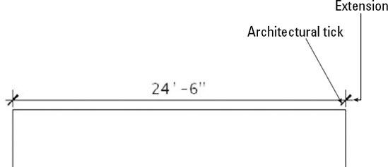
Figure 15.4. A typical architectural dimension showing the text above one dimension line, an architectural tick, and the dimension line extending slightly beyond the extension lines.
The Baseline spacing text box determines the distance between successive dimension lines when you create baseline dimensions with the DIMBASELINE command. This specification creates evenly spaced dimension lines. (In Chapter 14, I discuss the DIMSPACE command, which lets you evenly space any linear or angular dimensions.)
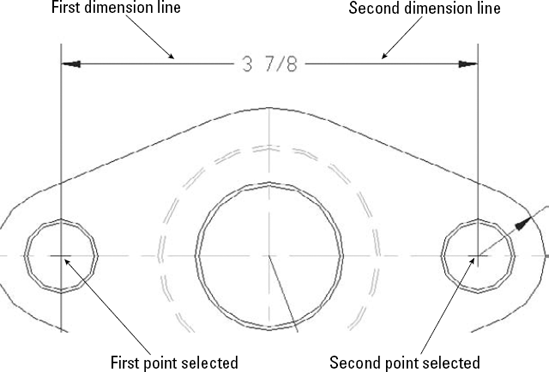
In some dimension styles, the dimension text splits the dimension line into two parts, as shown in Figure 15.5. This creates two dimension lines. You can suppress — that is, turn off — the first or second dimension line (or both dimension lines) by checking the appropriate box (or boxes). The first line is nearest where you specified the first extension-line origin. (If you selected an object instead of specifying two extension-line origins, you may not be able to predict which dimension line is the first and which is the second. Experiment.) You would usually suppress dimension lines when they interfere with other dimensions or with objects in your drawing. (The DIMBREAK command, which I cover in Chapter 14, breaks dimensions where they cross objects. You may be able to break a dimension instead of suppressing one of the dimension lines.)
As with dimension lines, you can pick a color for the extension lines that differs from that of the rest of the dimension. Click the Color drop-down list and choose a color. Choose Select Color to open the Select Color dialog box if you want a nonstandard color. The default color is ByBlock so that extensions take on the color of the current layer or color setting.
You can choose a separate linetype for each extension line. Choose the linetype that you want from the drop-down lists. If the linetype that you want isn't listed, click Other to open the Select Linetype dialog box, where you can load the linetype that you need.
Extension lines typically extend slightly past the dimension line, as you can see in some of the figures in this chapter. Use the Extend Beyond Dim Lines text box to specify this extension distance.
Extension lines don't usually touch the object that they dimension to make it easier to distinguish the dimension from the object. Use the Offset from Origin text box to define the distance from the specified points on the object to the extension lines.
Extension lines usually vary in length throughout a drawing, depending on the shape of the objects that you're dimensioning. However, sometimes you may want the extension lines to all be the same length, even if they don't reach near their objects. This method avoids dimension lines crossing each other when you're dimensioning a complex shape.
To specify fixed-length extension lines, check the Fixed Length Extension Lines check box and specify the length in the Length text box.
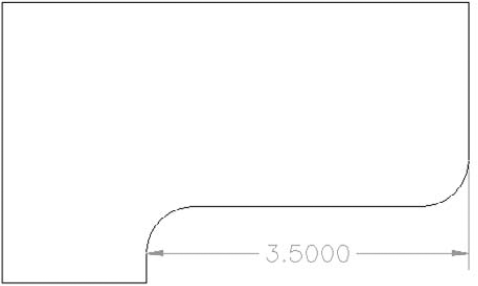
You can suppress the first or second extension line (or both lines) so that either or both are not visible. To do this, check the appropriate box (or boxes). Figure 15.6 shows a dimension with the first extension line suppressed.
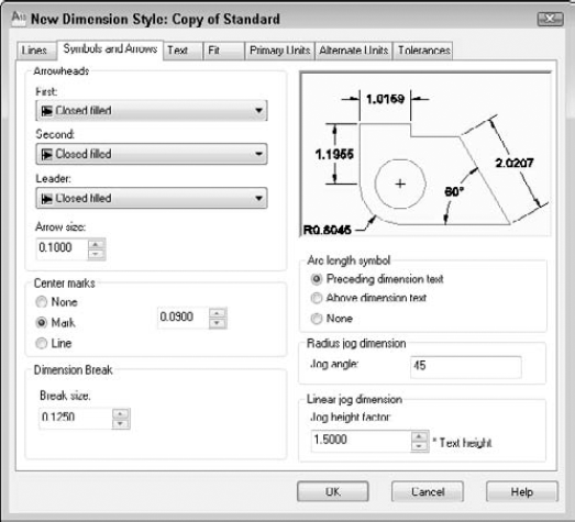
The Symbols and Arrows tab organizes your settings related to arrowheads and certain dimension-related symbols, as shown in Figure 15.7. For example, you can define center marks and arc length symbols on this tab.
The Arrowheads section controls the arrowheads at the ends of dimension lines. You don't actually have to use arrowheads, as you saw in Figure 15.4. You can also set the first and second arrowheads individually. However, if you change the first arrowhead, the second one follows suit, assuming that you want both ends of the dimension to look the same. To specify two different arrowheads, choose an arrowhead in the first drop-down list and then in the second drop-down list.
You can create and use your own arrowhead:
In any drawing, create the arrowhead that you want with a unit size of 1.
Make a block out of it. For an arrow-shaped block, pick the point of the arrow for the insertion point and create it pointing to the right. You may have to experiment with the right insertion point. Save the block. (See Chapter 18 for instructions on creating blocks. You can't use annotative blocks as arrowheads.)
In the first and second drop-down lists, choose User Arrow. The Select Custom Arrow Block dialog box opens, displaying the blocks available in the drawing.
Choose the block that you want from the drop-down list.
Click OK.
Figure 15.8 shows a dimension with a user arrow.
Tip
You can set a different arrow for leaders. Choose the arrow that you want from the Leader drop-down list.
Set the size of the arrowhead in the Arrow Size text box. As explained later in this chapter in the discussion of scale, you should use the final size that you want to see when the drawing is plotted on paper.
The Center Marks section of the Symbols and Arrows tab in the New Dimension Style dialog box specifies how you want to mark the centers of arcs and circles when you choose Annotate tab
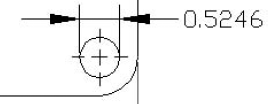
Specify the size of the center mark or centerline in the text box to the right of the Center Marks section. For center marks, the size is the distance from the intersection of the two lines to their endpoints. If you use centerlines, the size also determines the distance from the circle quadrants to the end of the centerlines.
In the Dimension Break section, specify the break size. A dimension break is a gap in the dimension where it crosses an object. I discuss dimension breaks (the DIMBREAK command) in Chapter 14.
The Arc Length Symbol section is for specifying the location of the symbol used when you dimension arc lengths. By default, the symbol goes before the dimension value, but you can choose to put it on top or omit it completely.
The Radius Jog Dimension section lets you specify the angle used when you create a jogged dimension for circles or arcs with large radii. A jogged dimension is a small dimension that doesn't reach to the center of the circle or arc. For more information on jogged dimensions, see Chapter 14.
In the Linear Jog Dimension section, specify a jog height factor for linear jogs. A jog is a zigzag symbol that indicates that the object is not drawn to scale, usually due to space limitations. For more information, see Chapter 14. You specify the size in relation to the text height for the dimension. The default is 1.5 times the text height. I discuss dimension text height in the next section.
Because the Standard dimension style is closest to mechanical drafting standards, in the following exercise you start to create an architectural dimension style, using the Standard style as a base. This requires you to make a maximum number of changes, thereby letting you become as familiar as possible with the dimension style settings. Here you practice controlling dimension lines and arrows.
Note
The drawing used in the following exercise on controlling dimension lines and arrows, ab15-a.dwg, is in the Drawings folder on the DVD.
STEPS: Controlling Dimension Lines and Arrows
Open
ab15-a.dwgfrom your DVD.Save the file as
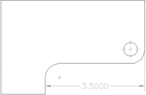
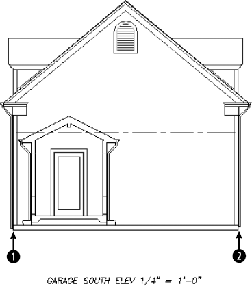
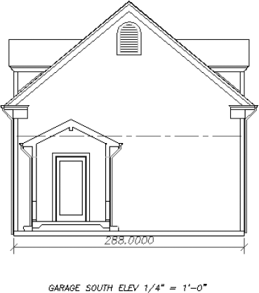
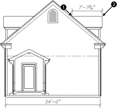
ab15-01.dwgin yourAutoCAD Biblefolder. This drawing is an elevation of a garage, as shown in Figure 15.10. Ortho mode and Object Snap should be on. Set running object snaps for Endpoint and Intersection. The Dim layer is current.To see what the Standard dimension style looks like, choose Home tab

Click Zoom on the status bar and specify a window near


Click the Symbols and Arrows tab if it isn't on top. In the Arrowheads section, choose Oblique from the first drop-down list. The size should be 3/16″.
Click the Lines tab. In the Dimension Lines section, type 3/32 in the Extend Beyond Ticks text box. (Because of the units precision setting — which you set with the UNITS command — this value is rounded off to 1/8″ in the display, although the value is still 3/32.) Click OK to return to the Dimension Style Manager.
In the Dimension Style Manager, notice that the arrows have been changed to ticks in the preview. Click Close.
Select the dimension that you created in Step 3. Choose Home tab
Save your drawing. Keep this drawing open if you're continuing on to the next exercise.
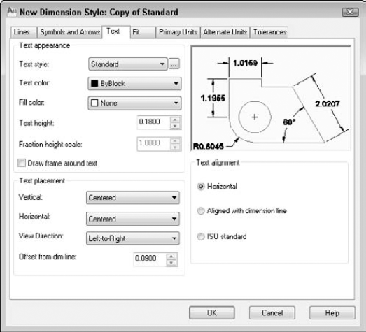
You can format the text of the dimension for readability and to match other text in your drawing. In the New Dimension Style dialog box, the Text tab, shown in Figure 15.11, controls text appearance, placement, and alignment.
You have full control over dimension text appearance, as you do over any other text in your drawing. To specify a text style for your dimension text, choose a text style from the Text style drop-down list. You may want to create a special text style, such as Dim Text, for dimension text, to give you the flexibility to alter dimension text without changing other text in your drawing. Create the dimension text style before creating your dimension style. If you want the dimension to be annotative, its text style should also be annotative.
Note
See Chapter 13 for a discussion of text styles.
Choose a color from the Text Color drop-down list. You can pick a color for the dimension text that differs from that of the rest of the dimension. The default color is ByBlock so that dimensions take on the color of the current layer or color setting. Use this setting only if you want the dimension text to be a different color from your dimension layer color. To choose a nonstandard color, choose Select Color from the drop-down list to open the Select Color dialog box.
You can create a block of color around the dimension text so that if other objects are behind the dimension, you can still read the dimension text clearly. To add a color, choose one from the Fill Color drop-down list.
Choose the height for your dimension text. When you set the text style height to zero, you can set the height in the New Dimension Style dialog box. Otherwise, the text style height takes over. It's much easier to make all your dimension style adjustments in one place than to make changes in the text style as well.
If your unit type uses fractions, use the fraction height scale to set a ratio of fraction text to whole text. This option is available only if your units specify the use of fractions. You may want the fractions to be smaller than whole numbers. A scale of 0.5 makes the fractions half the size of whole numbers; the resulting overall fraction is slightly higher than the whole numbers of the dimension text.
Some dimension styles require a border around the dimension text. If you want to include a rectangular border, check the Draw Frame Around Text check box.
The Vertical drop-down list affects how text is justified relative to the dimension line. As you make changes, be sure to look at the preview to see whether the results are what you want. You have the following options:
Centered. Centers the text in the dimension line, breaking the dimension line into two. This is typical for mechanical drafting. You can see an example in Figure 15.5.
Above. Places text above the dimension line. This is typical for architectural drafting. You can see an example in Figure 15.4.
Outside. Places the text on the side of the dimension line that is farthest from the object that you're dimensioning.
JIS. Places text in conformation to the Japanese Industrial Standards rules, which vary the placement according to the angle of the dimension line.
BELOW. Places text below the dimension line.
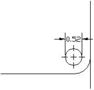
The Horizontal drop-down list affects the placement of dimension text between the extension lines. Here again, you have a handy visual confirmation of your choice. You have the following choices:
Centered. This is the default. It centers text between the two extension lines.
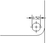
At Ext Line 1. Places the text next to the first extension line. The first extension line is always the first point that you specified at the
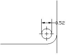
Specify first extension line origin or <select object>:prompt. The picture and the words Horizontal Justification can be especially confusing for vertical dimensions. If you aren't consistent in how you pick your dimensions, you can get some strange results.At Ext Line 2. Places the text next to the second extension line. The comments for the previous option apply to this option as well.
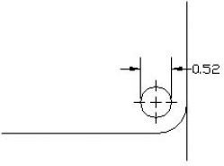
Over Ext Line 1. Places the text over the first extension line. The comments for the At Ext Line 1 option apply to this option as well.
Over Ext Line 2. Places the text over the second extension line. The comments for the At Ext Line 1 option apply to this option as well.
Left-to-Right. Displays the text starting on the left reading to the right.
Right-to-Left. Displays the text starting on the right reading to the left.
Use the Offset from Dim Line text box to set the gap between the dimension text and the dimension line. This sets the DIMGAP system variable. If the dimension line is broken, the gap is the space between each side of the dimension text and the two dimension lines. If the dimension line is unbroken and the text is above the line, the gap is the space between the bottom of the text and the dimension line. The gap also controls the space between the box created for Basic tolerance dimensions and the text inside them. Basic tolerances are discussed in the "Formatting tolerances" section later in this chapter.
Tip
When trying to fit dimension text, lines, and arrows into a narrow space, AutoCAD and AutoCAD LT also use the gap (the DIMGAP value) to calculate the minimum space required on either side of the dimension text. Therefore, reducing the gap can help fit more of the dimension elements between the extension lines.
Different disciplines have different standards for aligning dimension text. The Text Alignment section of the Text tab affects how the text is aligned relative to the dimension line, as follows:
Horizontal. Keeps text between the extension lines horizontal, regardless of the angle of the dimension line (typical of mechanical drawings).
Aligned with Dimension Line. Keeps text at the same angle as the dimension line (typical of architectural drawings).
ISO Standard. Uses the ISO standard, which aligns text with the dimension line when text is inside the extension lines, but aligns text horizontally when text is outside the extension lines (because of a tight fit).
Note
The drawing used in the following exercise on defining dimension text, ab15-01.dwg, is in the Results folder on the DVD.
STEPS: Defining Dimension Text
If
ab15-01.dwgis open from the previous exercise, use it for this exercise as well. Otherwise, openab15-01.dwgfrom theResultsfolder of the DVD. Ortho Mode and Object Snap should be on. Set running object snaps for Endpoint and Intersection. The Dim layer is current.Save the file as
ab15-02.dwgin yourAutoCAD Biblefolder.Choose Home tab
In the Text Appearance section, choose ROMANS as the text style.
In the Text Placement section, choose Above from the Vertical drop-down list.
In the Text Alignment section, choose Aligned with Dimension Line. Although mechanical dimensions usually require horizontal text, architectural dimensions require that the text be aligned with the dimension line.
Click OK and then click Close to update the dimension to include the changes. The text is still too tiny to see clearly.
Save your drawing. Keep this drawing open if you're continuing on to the next exercise.
When there is not enough room to place the arrowheads, dimension line, and text between the extension lines, some elements of the dimension need to go outside the extension lines. The Fit tab, shown in Figure 15.12, lets you specify how you want to handle this situation.
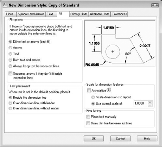
The Fit Options section determines which elements are moved outside the extension lines — text, arrows, or both — when they can't fit inside the extension lines. These are among the hardest of the dimension styles options to understand, yet they can greatly affect how your dimensions appear.
Warning
The Fit options specify what goes outside the extension lines. For example, choose the Arrows option to place the arrows outside the extension lines if there is not enough room for them. Be careful, or you'll get a result that is the opposite of what you intended.
Here are your choices:
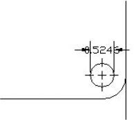
Either Text or Arrows (Best Fit). Puts whatever fits inside the extension lines. The arrowheads might fit inside and the text might not, or the other way around. If there isn't enough room for either text or arrows, then they both go outside the extension lines. Figure 15.13 shows a dimension using this option.
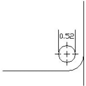
Arrows. If there is not enough room for both the text and the arrows between the extension lines, the arrows go outside and the text goes between the arrows. Figure 15.14 shows a dimension using this option. The results of this option happen to look the same as Figure 15.13, but a different setting produced them.
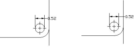
Text. If there isn't enough room for the text and the arrows between the extension lines, the text goes outside and the arrows go between them. Figure 15.15 shows a dimension using this option.
Both Text and Arrows. Keeps the text and arrows together — between the extension lines if there is enough room, and outside the extension lines if there is not. Figure 15.16 shows a dimension using this option.
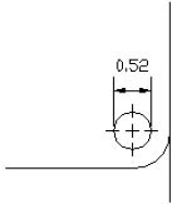
Always Keep Text between Ext Lines. As it says, this option always keeps the text between the extension lines, even if they don't fit. Figure 15.17 shows a dimension using this option.
Suppress Arrows If They Don't Fit Inside the Extension Lines. Use this check box to suppress the display of arrows completely if they don't fit inside the extension lines (instead of putting them outside). This option is used together with one of the previous options. Figure 15.18 shows a dimension using this option with the Either Text or Arrows (Best Fit) option.
The Text Placement section determines where you want the dimension text when it isn't in its default position, due to a tight fit. Your options are:
Beside the Dimension Line. Places the dimension text next to the dimension line, but outside the extension lines. Figure 15.19 shows a dimension using this option, as well as the same dimension edited to move the text off the model. You can move the text anywhere to the left or the right of the dimension line, but not above or below it. Editing dimensions is covered later in this chapter.
Over Dimension Line, with Leader. Places the dimension text over the dimension line and between the extension lines with a leader from the dimension line to the text. You can move the text anywhere to suit your needs and dimensioning conventions, as shown in Figure 15.20.
Over Dimension Line, without Leader. Places the dimension text over the dimension line and between the extension lines with no leader, as shown in Figure 15.21. You can move the text anywhere.

The Scale for Dimension Features section lets you specify the scale factor. The reason you need to specify a scale factor is because you may have to scale the drawing when you plot it. The scale factor adjusts the size of dimension text (unless a nonzero text style height controls the text), arrowheads, spacing, and so on. It has no effect on the content of dimension text — that is, it does not affect actual measurements. So many size options are possible in a dimension style that you could spend all day trying to multiply each size option by the scale. Then if you have to change the scale of the drawing, you would need to recalculate all the size specifications. Setting the Overall Scale factor tells AutoCAD or AutoCAD LT to automatically multiply every size specification by the scale factor.
To scale dimensions according to the scale of the layout, check the Scale Dimensions to Layout option. You would use this feature if you plan to use more than one viewport, each with a different scale factor. If not, you can choose an overall scale, which would be the scale factor that you plan to use; check the Use Overall Scale Of option and enter a scale.
The annotative feature, which is available for text, hatches, blocks, and dimensions, replaces the previous dimension scaling. Therefore, when you check the Annotative check box, the two options become unavailable.
Note
Scale factors are discussed in detail in Chapter 5. See Chapter 17 for a discussion of scaling dimensions in a paper space layout (including the use of annotative dimensions) and placing dimensions on a layout.
In the Fine Tuning section, if you check the Place Text Manually option, the horizontal text placement settings are ignored, and the point that you pick at the Specify dimension line location or [Mtext/Text/Angle/Horizontal/Vertical/ Rotated]: prompt is used. Before you click, as you move the cursor along the dimension line, you can see the text following the cursor.
Check the Draw Dim Line Between Ext Lines option to force a dimension line between the extension lines, even when there isn't room for text or arrows, as shown in Figure 15.22.
Note
The drawing used in the following exercise on setting dimension fit, ab15-02.dwg, is in the Results folder on the DVD.
STEPS: Setting Dimension Fit
If
ab15–02.dwgis open from the previous exercise, use it for this exercise as well. Otherwise, openab15-02.dwgfrom theResultsfolder of the DVD. Ortho Mode and Object Snap should be on. Set running object snaps for Endpoint and Intersection. The Dim layer is current.Save the file as
ab15–03.dwgin yourAutoCAD Biblefolder.Choose Annotate tab
On the Fit tab, in the Text Placement section, choose Over Dimension Line, with Leader.
In the Fine Tuning section, check Draw Dim Line Between Ext Lines. Architectural dimensions customarily place a line between the extension lines, even if the text cannot fit.
Because the drawing's scale is ¼″=1', or 1:48, type 48 in the Use Overall Scale Of text box.
Click OK. Click Close to return to your drawing.
Save your drawing. You can finally see the dimension! It should look like Figure 15.23. Keep this drawing open if you're continuing on to the next exercise.
The primary units define the type of units used to display the dimension in your drawing. You need to set primary units separately from the units for the drawing, which affect coordinate display but not dimensions.
Click the Primary Units tab, shown in Figure 15.24, to set the format and precision for linear and angular dimensions. You should already be familiar with setting units, which I discuss in Chapter 5. You must set your units for dimensions separately.
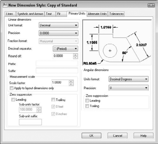
To get the look and accuracy that you want, you should specify the format and precision of your linear dimensions. The New Dimensions Style dialog box provides settings for linear dimensions. You have the following options:
Choose a format from the Unit Format drop-down list. You have the same choices as in the Drawing Units dialog box: Scientific, Decimal, Engineering, Architectural, and Fractional, as well as an additional option, Windows Desktop.
Note
To see the current Windows Desktop units setting, choose Start
Choose a precision (the number of decimal points or the fraction denominator) from the Precision drop-down list.
Choose a fraction format from the Fraction Format drop-down list. This option is available only if the format that you chose uses fractions. Horizontal places a horizontal line between stacked numerators and denominators. Diagonal uses a diagonal slash between the stacked numerator and denominator. Not Stacked uses a diagonal line between the numerator and denominator, which are not stacked. You can see the effect of each choice in the preview box.
Choose a decimal separator. This option is available only if the format that you chose uses decimals. You can choose from a period, a comma, and a space.
Use the Round Off text box to round off linear dimension distances. For example, you can round to the nearest 0.1 unit or ½ inch.
Use the Prefix and Suffix boxes to add a prefix or suffix that you want to place before or after every dimension. For example, you might want to add a suffix of mm after every dimension if you're measuring in millimeters and giving the drawing to a client who usually sees dimensions in inches.
You can use the Scale Factor text box to set a scaling factor for linear dimensions, including radial and diameter dimensions, and ordinal dimensions. This factor changes the actual measurement text. For example, if you draw a line 2.5 units long and you specify a linear scale of 0.5, the object is dimensioned as 1.25 units. You could set this scale to 25.4 to use metric measurements on a drawing that you have created with U.S. measurements. This can occur if you're sending the same drawing to certain clients in the United States and other clients elsewhere in the world. You can also use this scale in conjunction with alternate units, as explained in the next section.
Check the Apply to Layout Dimension Only option to apply the linear scaling factor only to layout (paper space) dimensions.
In the Zero Suppression section, choose whether you want to suppress leading and trailing zeros. If you suppress leading zeros, a number such as 0.375 appears as .375. If you suppress trailing zeros, a number such as 3.7500 appears as 3.75.
Note
If you suppress leading zeros, you can choose to display a measurement of less than one unit in a subunit, which is an alternative, smaller unit.
You can use subunits with decimal units only. For example, if your units represent feet, instead of displaying a dimension value as 0.25 feet, you may want to display the measurement as 3″.
To do so, first check the Leading check box, to suppress leading zeros. Then specify the Sub-Units Factor value to set the number of subunits per unit. In the previous example, you would set the Sub-Units Factor to 12, because there are 12 inches in a foot. (If your units represent meters, you could set the Sub-Units Factor to 100 to show units of less than one in centimeters.)
Use the Sub-Units Suffix text box to specify a suffix for the dimension text. In the example you would set this value to ″, to represent inches. AutoCAD multiples the actual value (.25) by the subunit factor (12), adds the suffix, and displays the results (3″). (If your units represent meters and you want to show centimeters for subunits, set the suffix to cm.
For architectural units, you can choose to suppress 0 feet and 0 inches. If you suppress 0 feet, a number such as 0'-8″ becomes 8″. If you suppress 0 inches, a number such as 6'-0″ becomes 6'.
To get the look and accuracy that you need for angular dimensions, you should also set their format and precision. The Angular Dimensions section of the Primary Units tab lets you format angular measurements. You have the following options:
Choose from Decimal Degrees, Degrees Minutes Seconds, Gradians, and Radians.
Choose a precision from the Precision drop-down list.
In the Zero Suppression section, choose whether you want to suppress leading and trailing zeros for angular dimensions. For example, an angle of 37.0° would appear as 37° with the trailing zero suppressed.
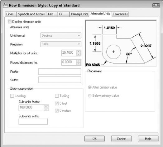
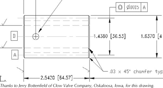
If you want, you can show an alternate set of units in your dimensions. The most common use of this feature is to show millimeters and inches together. Alternate units appear in square brackets. To show alternate units, click the Alternate Units tab of the New Dimension Style dialog box, as shown in Figure 15.25. Check the Display Alternate Units check box.
As you can see, this dialog box is very similar to the Primary Units tab, discussed in the previous section. Notice the default scale of 25.40 in the Multiplier for Alt Units text box. There are 25.4 millimeters to an inch. If your primary units are millimeters, you can set the linear scale to 0.03937, which is the number of inches to a millimeter. Of course, if your units are not inches but meters, miles, or something else, you need to make the appropriate calculations.
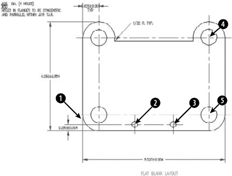
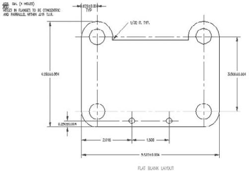
Figure 15.26 shows two dimensions with alternate units.
In the Placement section, choose one of the options to place alternate units after or below the primary units.
Note
The drawing used in the following exercise on defining primary units, ab15-03.dwg, is in the Results folder on the DVD.
STEPS: Defining Primary Units
If
ab15–03.dwgis open from the previous exercise, use it for this exercise as well. Otherwise, openab15–03.dwgfrom theResultsfolder of the DVD. Ortho Mode and Object Snap should be on. Set running object snaps for Endpoint and Intersection. The Dim layer is current.Save the file as
ab15–04.dwgin yourAutoCAD Biblefolder.Choose Annotate tab
In the Unit Format drop-down list, choose Architectural.
In the Precision drop-down list, change the precision to 0'-0 1/8″.
In the Fraction format drop-down list, choose Diagonal.
In the Zero Suppression section, uncheck the 0 Inches check box because architectural dimensions sometimes show 0 inches.
Click the Text tab. In the Fraction Height Scale text box, type .75.
Click OK. In the Dimension Style Manager, click Close to return to your drawing. The dimension is automatically updated and now looks appropriate for an architectural drawing.
To see how the stacked fractions appear, create a linear dimension from
Return to the previous view if you zoomed in. Save your drawing. It should look like Figure 15.27.
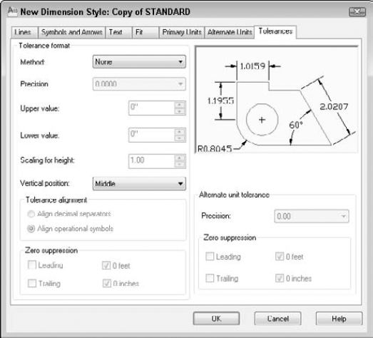
Tolerances are used in mechanical drafting to specify how much deviation is allowed from the exact measurement when the model is manufactured. Format the tolerance notation on the Tolerances tab of the New Dimension Style dialog box. The Tolerances tab is shown in Figure 15.28.
Note
The Tolerances tab formats regular dimensions. You can also create special Tolerance control frames, which have the same purpose, but are separate object types. I cover them in Chapter 14.
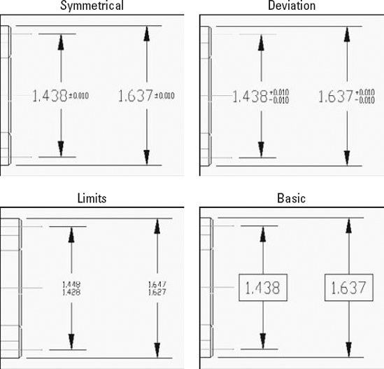
Use the Tolerance Format section to specify how you want the tolerances to be displayed. You can choose one of four tolerance methods from the Method drop-down list, as shown in Figure 15.29:
Symmetrical tolerances have the same upper and lower amounts and are shown with a plus/minus sign. The Upper Value text box is active so that you can type in the tolerance amount.
Deviation tolerances can have different upper and lower amounts and are therefore shown after separate plus and minus signs. When you choose a deviation tolerance, the Upper Value and Lower Value text boxes become active.
Limits dimensions include the upper and lower tolerances in the measurement. Use the Upper Value and Lower Value text boxes to type in the upper and lower tolerance amounts.
Basic dimensions place the dimension in a box.
In the Precision drop-down list, choose a precision value. Use the Upper Value text box to set the tolerance value for symmetrical tolerances. For deviation and limits tolerances, use both the Upper Value and Lower Value text boxes.
The Scaling for Height text box lets you scale the height of the tolerance relative to the dimension text height. Using smaller text for the tolerances is common. A value of 1 creates tolerance text that is equal to the dimension text height. A setting of 0.5 creates tolerance text that is half the size of regular dimension text.
Use the Vertical Position drop-down list to determine how the tolerances are aligned with the main dimension text. This setting has the greatest effect on Deviation tolerances that display two lines of text for the one dimension text line. You have the following choices:
Top. Aligns the tolerance text with the top of the dimension text
Middle. Aligns the tolerance text with the middle of the dimension text
Bottom. Aligns the tolerance text with the bottom of the dimension text
Note
The Vertical position setting also applies to stacked fractions, determining how the fractions are justified with the whole-number dimensions.
If you choose a Limits or Deviation tolerance, you can specify the alignment of stacked upper and lower tolerance values. You can align the values by the decimal separators (such as a decimal point) or by the operational symbols (such as the plus-minus symbol).
Use the Zero Suppression section to suppress leading or trailing zeros, or feet and inches. See the preceding explanation of the Primary Units tab for more information.
If you've turned on alternate units, you can separately set the precision and zero suppression for alternate unit tolerances in the Precision text box.
Click OK, and then click Close to return to your drawing. You're ready to start dimensioning!
You may need to edit dimension styles. Whether you want to use a different dimension style for a certain object or change the properties of a dimension style, you have the flexibility you need. You can change dimensions in the following ways:
Choose a new dimension style.
Create a variant of a dimension style for a certain type of dimension.
Modify the characteristics of the dimension style in use.
Override the dimension style with different dimension options for one dimension that you want to be an exception.
Chapter 14 covers some dimension editing techniques. This section explains how to make changes related to dimension styles.
To start using another dimension style, click the Dimension Style drop-down list in the Dimensions panel of the Annotate tab or the expanded Annotation panel of the Home tab, and choose the dimension style that you want to use.
Existing dimensions remain unchanged, but any new dimensions that you add from this point forward will use the new current dimension style.
Create a variant of a dimension style for a specific type of dimension, such as a leader or angular dimension. You might have an architectural dimension style with ticks (rather than arrows) at the end of the dimension lines, but you might want angular dimensions to have open arrows. Here are the steps to do this:
Choose Annotate tab
Click New.
From the Use For drop-down list, choose the type of dimension that you want to use with the new variant.
Click Continue.
Make the changes that you want, using the techniques described earlier in this chapter.
Click OK to return to the Dimension Style Manager. Here you see the variant listed under its base (parent) dimension style.
Click Close.
Dimensions of the type that you specified now take on the characteristics of the variant. For example, angular dimensions would have an open arrow.
You can change the dimension style used by an existing dimension. Select the dimension and then choose a new dimension style from the Dimension Style drop-down list in the Dimensions panel of the Annotate tab or the expanded Annotation panel of the Home tab.
Another method of changing a dimension's style is to open the Properties palette (press Ctrl+1) and select one or more dimensions. In the Properties palette, click the Dim style item in the Misc section and choose a new dimension style from the drop-down list. You can also change the dimension style of a selected dimension in the Quick Properties palette.
Tip
Select any dimension to open the Quick Properties palette, where you can change some of the properties of that dimension.
You can easily change a dimension style. The advantage of changing a dimension style is that all dimensions using that style are automatically updated. To change a style:
Choose Annotate tab
Choose the dimension style that you want to change from the list of styles.
Choose Modify.
AutoCAD opens the Modify Dimension Style dialog box, which is exactly the same as the New Dimension Style dialog box. Use the settings on all the tabs and make the changes that you want. Click OK to close these dialog boxes and return to the Dimension Styles Manager.
Click Close.
All dimensions automatically change to reflect the changed dimension style.
Tip
You can create a new dimension style from an existing dimension on the fly by using the Properties palette. Open the Properties palette. Click the arrow next to the type of change that you want to make, and make the change. After you're done, right-click in the drawing area and choose Dim Style
Sometimes you want to make an exception to a style for one dimension — for example, when suppressing an extension line in a tight space. It isn't often worthwhile to create a new dimension style for such a situation. To override a dimension style, simply change the properties of the dimension by using the Properties palette.
You can also create an override to the current dimension style. The override is like a subset of the dimension style. After you create the override, all new dimensions that you create using the dimension style include the override changes. To revert back to the original dimension style, you must delete the override. You also have the option to incorporate the override into the dimension style or save it as a new style.
To create a dimension style override, follow these steps:
Choose Annotate tab
Choose the dimension style for which you want to create an override (if it isn't already selected).
In the Dimension Style Manager, click Override.
The Override dialog box opens, which is just like the New (or Modify) Dimension Style dialog box. Make the changes that you want by using any of the tabs. Click OK.
In the Dimension Style Manager, you see the style override listed beneath the dimension style that you selected. Click Close.
New dimensions that you create using the dimension style that you selected now include the override properties.
To stop using the override, open the Dimension Style Manager, right-click the style override to open the shortcut menu, and do one of the following:
Choose Delete to delete the override.
Choose Save to Current Style to incorporate the override properties into the current dimension style.
Choose Rename to create a new dimension style from the override. You see a selection box around the name. Type a new dimension style name and press Enter. This action removes the override and replaces it with the new dimension style.
Removing the override doesn't change dimensions that you've already created with the override.
Tip
To quickly override a dimension's style, select the dimension. Then right-click and choose one of four options. Dim Text Position offers four suboptions to control the position of the dimension's text. Precision lets you quickly choose from 0 to 6 decimal places. The Dim Style option creates a new style from the selected dimension. Finally, the Flip Arrow option flips the selected arrow to the outside of the extension lines.
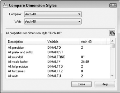
You can compare a dimension style with the current dimension style. To do this, follow these steps:
Choose Annotate tab
In the Compare and With drop-down lists, choose the two dimension styles that you want to compare. The resulting list shows the differences by system variable. For more information about system variables used in dimensions, see the sidebar "Dimension system variables."
Click Close twice to return to your drawing.
With proper planning, dimension styles make dimensioning much easier and produce more-uniform results. Although you can save dimension styles in your templates, you may sometimes need to work with someone else's drawing or an old drawing that doesn't contain the dimension styles that you need. As explained in Chapters 11 and 13, you can use the DesignCenter to import features from other drawings. To import a dimension style, follow these steps:
Choose View tab
In the left pane, navigate to the drawing that has the dimension style that you want.
Double-click the drawing icon or click its plus sign.
To see the list of the dimension styles, double-click the dimension style's icon in either the left or right pane.
Double-click the dimension style's icon to import it into your drawing.
Note
The Express Tools offer two commands, DIMIM and DIMEX, which enable you to save (export) and retrieve (import) dimension styles. Type these commands on the command line. For information on installing Express Tools, see Appendix A.
Note
The drawing used in the following exercise on changing dimension styles, ab15-b.dwg, is in the Drawings folder on the DVD.
STEPS: Changing Dimension Styles
Open
ab15-b.dwgfrom your DVD.Save the file as
ab15-05.dwgin yourAutoCAD Biblefolder. This is a tension arm for a commercial dryer, as shown in Figure 15.31. Ortho Mode and Object Snap should be on. Set running object snaps for Endpoint, Intersection, and Center. The Dim layer is current.The current dimension style is CIR. Choose Annotate tab
Choose Annotate tab
Choose Annotate tab
Start the DIMLINEAR command again. At the
Specify first extension line origin or <select object>:prompt, choose the intersection at

To list the overrides, choose Annotate tab
To remove the overrides (no tolerance and the first extension line suppressed), right-click
<style overrides>in the Dimension Style Manager and choose Delete. You get the message,Are you sure you want to delete ″<style overrides>″? Choose Yes. Click Close to return to the drawing.Start the DIMLINEAR command again. At the
Specify first extension line origin or <select object>:prompt, choose the intersection at
To compare the CIR and LIN dimension styles, open the Dimension Style Manager again. Choose Compare. LIN should appear in the Compare drop-down list. Choose CIR from the With drop-down list. The result is a list of the differences. Click Close twice to return to your drawing.
Save your drawing. It should look like Figure 15.32.
In this chapter, you gained a thorough understanding of how to use dimension styles to organize your dimensions. You read how to:
Define a dimension's lines and arrows
Define dimension text style and placement
Create an annotative dimension style
Fit dimensions into small spaces
Define the primary and alternate measuring units
Format tolerances
Create a variant of a dimension style for specific types of dimensions
Change dimension style used by a dimension
Modify a dimension style and update all dimensions that use that style
Override a dimension style for temporary changes
Update existing dimensions
Compare dimension styles
Copy dimension styles from other drawings, using the DesignCenter
In the next chapter, you learn how to draw complex objects.