
As you draw, you'll find that you often need to place the same group of objects several times in a drawing. An architect needs to place windows and doors many times in a plan layout of a house. An electrical engineer places electrical symbols in a drawing again and again. A mechanical model may include nuts, bolts, and surface finish symbols many times in a drawing. Blocks are groups of objects that you save and name so that you can insert them in your drawing whenever you need them. A block is one object, regardless of the number of individual objects that were used to create it. Because it's one object, you can easily move, copy, scale, or rotate it. If necessary, you can explode a block to obtain the original individual objects.
A great advantage of blocks is that by changing the block definition, you can update all the instances of that block in that drawing. Another advantage of blocks is that they reduce the size of the drawing file. A drawing stores the definition of a block only once, along with a simple reference to the block each time it's inserted, instead of storing each individual object in each block in the drawing database.
As soon as you have a block in a drawing, you can work with it as with any other object. You can snap to object snaps of the individual objects within blocks, as well as trim and extend to objects within blocks, even though you can't edit the individual objects. For example, you can draw a line from the midpoint of a line in a block.
Many disciplines use parts libraries that may consist of thousands of items. You use the block feature to save and insert these parts. You can save many blocks in a drawing or place each in a separate file so that you can insert them in any drawing you wish.
Dynamic blocks are blocks that contain parameters for insertion and editing. You can create a dynamic block that takes the place of numerous similar regular blocks by giving it the flexibility to take on various sizes, rotations, visibility variations, and more. Dynamic blocks support parametric constraints, which give them more intelligence.
You can attach attributes to blocks. Attributes are labels that are associated with blocks. Attributes have two main uses: to label objects and to create a simple database. You can use fields in your attributes to automate the generation of text. (Chapter 13 explains all about fields.)
This chapter explains how to make the most of blocks and attributes.
Any object or set of objects can be saved as a block. Creating a block is easy, but a little planning makes using it much simpler. Before you create a block, you need to understand how blocks are inserted and how you want to use the specific block that you're creating.
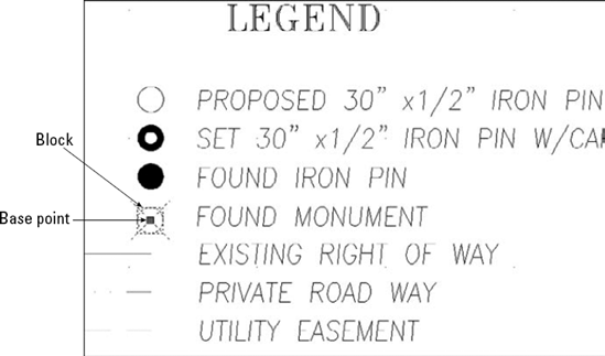
Figure 18.1 shows the legend for a plat drawing. Each legend symbol is a block that is then inserted in the drawing as needed. A symbol has been selected, and you can see that it has one grip at the base point. The base point is the point that you use to insert the block. Every block must have a base point. When you insert the block, the base point is placed at the coordinate that you specify for inserting the block — the insertion point. All the objects of the block are then inserted in their proper place relative to that insertion point.
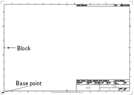
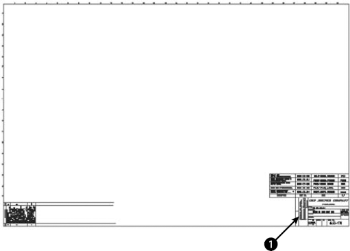
The base point does not have to be on the object, but it should be in a location that makes it easy to insert the block. Figure 18.2 shows a different sort of block, a title border/block. In this case, the base point is usually inserted at 0,0 of the drawing. By placing the base point at the lower-left corner of the border, you can easily place this block in any drawing. The base point is similar in concept to the justification point on text objects.
To create a block, first create the objects just as you want to save them. You may include other blocks as objects in your block. (A block within a block is called a nested block.)
After you've created the objects for your block, follow these steps:

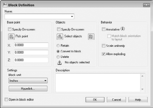
In the Name text box, type a name for the block. The name can be up to 255 characters, and spaces are allowed.
If you want to specify a base point in the dialog box, in the Base Point section, uncheck the Specify On-Screen check box. Then you can either click the Pick Point button to return to your drawing and specify a base point, or enter X, Y, and Z coordinates. Use an object snap on any of the objects in the block to place the base point somewhere on the block.
You can select objects for a block before starting the BLOCK command. If you have not done so, you can check the Specify On-Screen check box in the Objects section. When you click OK, you will get a prompt to select objects. Alternatively, you can click the Select Objects button, return to your drawing to select objects, and then return to the dialog box.
Choose how you want the objects of the block to be treated in the Objects section:
Retain. Keeps the objects that you selected as individual objects.
Convert to Block. Converts the objects to a block.
Delete. Deletes the objects. Use this option if you created the objects to insert them elsewhere and do not need the original objects. One advantage of deleting the objects is that their disappearance confirms that you selected the right objects.
Choose the insert units that you want to use when defining your block in the Settings section. (You can choose anything from microns to parsecs!) Let's say you work in kilometers and save a block with an insert unit of kilometers. When you insert a block, it will be measured in kilometers, rather than millimeters or inches. If the units aren't important to you, you can specify the units as Unitless.
If you want the block to be annotative, check the Annotative check box in the Behavior section of the dialog box. You can set up annotative objects to scale automatically to the scale of a viewport. When you make a block annotative, you can also check the Match Block Orientation to Layout check box to match the block's orientation to that of the paper space layout (portrait or landscape). You set a layout's orientation in the Page Setup or Plot dialog box. For more information, see Chapter 17.
Note
For more information on using annotative objects, see Chapter 17.
Check the Scale Uniformly check box to force any scaling of the block to scale at equal X and Y factors. This feature prevents distortion of the block. By default, this option is not checked. However, it's not available if you choose to make the block annotative.
The Allow Exploding check box lets you explode the block after you insert it. This option is checked by default.
If you want, enter a description for the block. The description is used by the DesignCenter. You can also add a hyperlink by clicking the Hyperlink button. (See Chapter 28 for more on hyperlinks.)
Check the Open in Block Editor check box if you know that you want to create a dynamic block. (I explain dynamic blocks later in this chapter.) Then when you click OK to close the dialog box, the Block Editor immediately opens.
Click OK to return to your drawing.
The definition of the block is now stored in the drawing, ready for you to insert as many times as needed. If you selected Delete, your objects disappeared. You can retrieve them by using the one command with a sense of humor: OOPS. The OOPS command restores the last object or set of objects that you erased. This command works whether you used the ERASE command or created a block, and even if you used some other command in the meantime. By contrast, UNDO undoes commands only in the order that you executed them.
If you make a mistake, or if you want to change the block in some way, you can redefine it. If you just created the block, use UNDO and make any necessary changes. If you created the block earlier, follow these steps:
Insert the block and explode it. (Exploding is covered later in this chapter.)
Make the desired changes and repeat the process of defining the block, using the same name for the block.
Warning
When you specify the name of the block, you should type it, rather than choose it from the Name drop-down list. Choosing the name from the list replaces selected objects that you want to be in the new version of the block with the objects from the previous block definition, and sets the insertion point to 0,0.
Click Redefine when the message asks whether you want to redefine the block.
Redefining a block that has been inserted in your drawing updates all the blocks in that drawing. This is a powerful technique to control your drawing. If you have repetitive symbols in your drawing, it's worthwhile to make blocks out of them just so that you can make this type of global change if necessary.
Note
The drawing that you need for the following exercise on creating a block, ab18-a.dwg, is in the Drawings folder on the DVD.
STEPS: Creating a Block
Open
ab18-a.dwgfrom the DVD.Save the file as
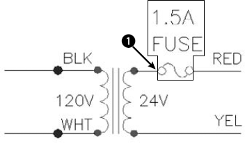
ab18-01.dwgin yourAutoCAD Biblefolder. This is a small portion of an electrical schematic drawing, as shown in Figure 18.4. Object Snap should be on. Set running object snaps for Endpoint, Quadrant, and Intersection.In the Name text box of the Block Definition dialog box, type 1-5 amp fuse.
In the Base Point and Objects sections, check the Specify On-screen check box.
In the dialog box's Objects section, choose Delete. The Insert Units should be Unitless. Leave the Description blank. The Open in Block Editor check box should not be checked.
Click OK.
In the drawing, at the
Specify insertion base point: prompt, use the Quadrant object snap to pick
At the
Select objects:prompt, select the boxed objects shown in Figure 18.4 (the two lines of text, the two circles, and the two arcs). Press Enter to end selection.To check that the block has been created, choose Home tab

Save your drawing.
You can use the DesignCenter (as explained later in this chapter) to insert blocks from any drawing. Nevertheless, many users organize their blocks in their own files so that they can be easily stored and located. Parts and symbols libraries are made up of many individual drawing files, one for each part or symbol. These libraries are a powerful aid to drawing more efficiently.
To save a block as a file, follow these steps:
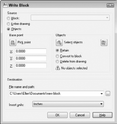
Type wblock

In the Source section, choose how you want to create the drawing file:
Block. Use this option when you've already created the block and now want to save it as a drawing file. Choose the block from the drop-down list.
Entire drawing. Use this option to make a copy of your drawing.
Objects. Use this option to start defining the block in the same way that you define a block within a drawing, as described in the preceding section of this chapter. The Base Point and Objects sections become available.
Choose the location (drive and folder) for the file in the File Name and Path text box. If you're creating the file from objects, insert a name for the file in place of the default
New Blockat the end of the path.In the Insert Units drop-down list, choose the units that you want for your block, or choose Unitless for no units.
If you make a mistake when selecting objects to write to a file with WBLOCK, or you want to change the objects in the file, you can replace the file. Start WBLOCK and type the name of the block file that you want to change. Be sure to choose the same file location. When you click OK, a message asks whether you want to replace the existing file. Click Replace the Existing filename.dwg.
Note
The drawing that you need for the following exercise on saving a block to a file, ab18-b.dwg, is in the Drawings folder on the DVD.
STEPS: Saving a Block to a File
Open
ab18-b.dwgfrom the DVD.Save the file as
ab18-02.dwgin yourAutoCAD Biblefolder. This is a large titleblock, as shown in Figure 18.6. Object Snap should be on. Set a running object snap for Endpoint.Type wblock
In the Source section of the dialog box, choose Objects. In the Objects section, click Select Objects.
Use Zoom Window to zoom in on the text at the bottom-right corner of the titleblock. At the
Select objects:prompt, select all the 90°-rotated text atIn the Base Point section, click Pick Point. Use the Endpoint object snap to pick the bottom-left corner of the box containing the text that you selected. Using this base point lets you easily place the text in the box at any time.
In the Objects section, choose Delete from Drawing.
In the File Name and Path text box, type notes-tol after the path, which should already be set to your
AutoCAD Biblefolder. Click OK to save the block as a file.Type oops
Choose View tab
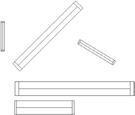
You insert blocks that are defined in a drawing in the same way as separate drawing files. After you choose the location, you can change the size and rotation of the block. This capability is ideal for parts libraries. You can create parts at the size of 1 unit and then scale or rotate them as needed. Figure 18.7 shows a window block inserted at various scales and rotation angles. (You could also create one dynamic block with the capability of inserting it at various scales and rotation angles. I cover dynamic blocks later in this chapter.)
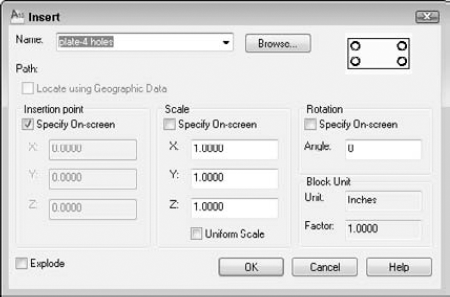
To insert a block or file, follow these steps:

Note
If the block is annotative, you see an annotative icon next to the block's preview.
You can insert a block or a file as follows:
To insert a block from within your drawing, click the Name drop-down list and choose one of the existing blocks.
To insert a file, click Browse. The Select Drawing File dialog box opens. Locate the file's drive and folder, and then choose the file. A preview appears to the right. Click Open. The Insert dialog box displays the path of the file.
Uncheck Specify On-screen in the Insertion Point, Scale, and Rotation sections if you want to specify the insertion point, scale, and rotation angle in the dialog box. Then provide the requested information in the dialog box.
Check the Explode check box if you want to insert the block as individual objectsrather than as one block object. The Explode check box is disabled if you did not check the Allow Exploding check box in the Block Definition dialog box when you created the block.
Click OK to close the Insert dialog box.
Tip
While you're dragging the block and before you specify an insertion point, if the Properties palette is open, you can change the properties of the block. For example, you can choose a layer to insert the block on a layer other than the current layer.
If any of the Specify On-Screen check boxes were checked, the command line prompts you for the necessary information:
At the
Specify insertion point:prompt (which varies, depending on whether or not you checked the Explode check box in Step 4), specify the insertion point. You see the block with its base point at the cursor, so you can judge how it looks.At the
Enter X scale factor, specify opposite corner, or [Corner/XYZ] <1>:prompt, press Enter to accept the default scale factor of 1, or type another scale. The Specify Opposite Corner option lets you define a square box whose side defines the scale factor. A side of 1 unit results in a scale factor of 1. If you specify the X scale factor, the command line prompts you for the Y scale factor. The default is the same scale as X, but you can specify a different one. For 3D models, use the XYZ option to specify all three scale factors. (If you checked Explode, the prompt is slightly different, and you specify the scale factor for all directions at once. If the Uniform Scale check box is checked, the prompt asks you for a scale factor.)At the
Specify rotation angle <0>:prompt, type in a rotation angle. You can also pick a point to use the angle from the insertion point to the point that you picked as the rotation angle. This technique is useful for aligning a block with an existing object.
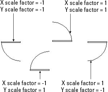
After you provide all the necessary information, the command inserts the block or file. A negative scale factor for any of the axes creates a mirror image of the block or file. When you specify a negative X scale axis, the block is mirrored around the Y axis. When you specify a negative Y scale axis, the block is mirrored around the X axis. Figure 18.9 shows a door block inserted with positive and negative scale factors. The rotation angle of all the blocks is 0 degrees. By combining negative and positive scale factors with rotation angles, you can get any door configuration that you want. Sometimes it can be difficult to visualize the result of a negative scale combined with a rotation angle. See the sidebar, "Presetting scale and rotation while inserting a block," for a solution. Dynamic blocks also offer a way to insert blocks at various scales and rotation angles.
When you insert a drawing file, paper space objects are not included in the block definition created in your drawing. To insert paper space objects in another drawing, open the original drawing and define the objects as a block. Then use the DesignCenter to insert that block into any other drawing.
Double-click the block's icon to open the Insert dialog box so that you can specify exactly how you want to insert the block, just as I described earlier for blocks within a drawing.
Drag the block's icon onto the drawing area to insert the block at the point where you release the mouse button, using the default scale and rotation.
You can use the DesignCenter to insert entire drawings. In the left pane, navigate to the folder containing the drawing. The drawings are then listed in the right pane. Choose a drawing and drag it onto the drawing area. On the command line, you'll see the -INSERT command, the command-line version of INSERT. You can simply specify an insertion point, scale, and rotation, or you can use the options described in the sidebar "Presetting scale and rotation while inserting a block."
Note
The DesignCenter is covered in more detail in Chapter 26. You can also insert blocks from a tool palette. Many people use tool palettes, also covered in Chapter 26, as the primary way to insert blocks from a block library. You can quickly create a tool palette containing all the blocks in a folder.
Note
The drawings that you need for the following exercise on inserting blocks, ab14-b.dwg and ab18-c.dwg, are in the Drawings folder on the DVD.
STEPS: Inserting Blocks
Open
ab18-c.dwgfrom the DVD.Save the file as
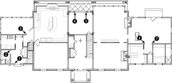
ab18-03.dwgin yourAutoCAD Biblefolder. This is the floor plan of the first floor of a house, as shown in Figure 18.10. Many of the doors and a toilet need to be inserted. Object Snap should be on. Set running object snaps for Endpoint and Midpoint. The current layer is Door.Use Zoom Window to zoom in on the left wing of the house.

Tip
If you make a mistake while inserting a door, press Esc if you're in the middle of the prompts. If you've completed the command, click Undo on the Quick Access toolbar or erase the door and start over.
As you move the cursor, you can see the dragged image of a door. This image shows you the block at an X and Y scale of 1, and a 0-degree rotation angle. Follow the prompts:
Specify insertion point or [Basepoint/Scale/X/Y/Z/Rotate]:
Use the Endpoint object snap to pickin Figure 18.10. Enter X scale factor, specify opposite corner, or [Corner/XYZ] <1>:−1Enter Y scale factor <use X scale factor>:1Specify rotation angle <0>:270(You could also specify −90 degrees.)Repeat the INSERT command. The Insert dialog box already shows the DOOR block. Click OK. Follow the prompts. You'll probably want to zoom into the area of

Specify insertion point or [Basepoint/Scale/X/Y/Z/Rotate]:
Pickin Figure 18.10. Enter X scale factor, specify opposite corner, or [Corner/XYZ] <1>:2/3Enter Y scale factor <use X scale factor>:Specify rotation angle <0>:180If you zoomed in for the previous step, return to the previous view by using Zoom Previous (View tab
Specify insertion point or [Basepoint/Scale/X/Y/Z/Rotate]:
Pick
in Figure 18.10. Enter X scale factor or specify opposite corner, or [Corner/XYZ] <1>:−3/4Enter Y scale factor <use X scale factor>:3/4Specify rotation angle <0>:315Zoom in to the area around

Specify insertion point or [Basepoint/Scale/X/Y/Z/Rotate]:
Pickin Figure 18.10. Enter X scale factor, specify opposite corner, or [Corner/XYZ] <1>:1Enter Y scale factor <use X scale factor>:Specify rotation angle <0>:270Repeat the INSERT command and click OK. Follow the prompts:
Specify insertion point or [Basepoint/Scale/X/Y/Z/Rotate]:
Pick
in Figure 18.10. Enter X scale factor, specify opposite corner, or [Corner/XYZ] <1>:−1Enter Y scale factor <use X scale factor>:1Specify rotation angle <0>:90Zoom in on the area around

Specify insertion point or [Basepoint/Scale/X/Y/Z/Rotate]:
Pickin Figure 18.10. Enter X scale factor, specify opposite corner, or [Corner/XYZ] <1>:−2/3Enter Y scale factor <use X scale factor>:2/3Specify rotation angle:270Repeat the INSERT command and click OK. Follow the prompts:
Specify insertion point or [Basepoint/Scale/X/Y/Z/Rotate]:
Pick
in Figure 18.10. Enter X scale factor, specify opposite corner, or [Corner/XYZ] <1>:2/3Enter Y scale factor <use X scale factor>:Specify rotation angle:90Beneath the doors that you just inserted is a water closet with a toilet. Pan down to it by clicking Pan on the status bar and dragging. Erase the toilet, which is a block. Change the current layer to FIXTURE.

Double-click TOILET2. You see a preview at the bottom of the DesignCenter. (If you don't, click Preview on the DesignCenter toolbar.) The Insert dialog box opens. Because you can see the preview, you know the rotation angle is correct; you can assume that the scale is correct because toilets are generally about the same size. The Insertion Point Specify On-Screen check box should be checked. The other Specify On-Screen check boxes should be unchecked. Click OK.
Drag the toilet into the water closet and use a Midpoint object snap to place it at the middle of the bottom wall of the water closet. If you want, close the DesignCenter by clicking its Close button.
Do a Zoom Extents and save your drawing.
The MINSERT command (AutoCAD only) lets you insert blocks (but not annotative blocks) in a rectangular array. Type minsert
Several factors require care when working with blocks. Large libraries of blocks need to be well managed so that you can find the block that you need quickly. You also need to consider the issue of which layers you use when you define your blocks so that you get the desired results when you insert them.
Tip
You can use the QSELECT command to select all instances of a block from a drop-down list. Choose Block Reference as the object type and Name as the property. From the Value drop-down list, choose the block that you want.
You may want a block to take on the current layer when inserted, or to retain its original layer. You can manage block layers, along with their color and linetype properties, to obtain the desired result. A block can be defined in four ways to determine which layer, color, linetype, and lineweight properties it will use when you insert it, as shown in Table 18.1.
As Table 18.1 makes clear, two of the methods (setting the objects to ByBlock and creating them on layer 0) create chameleon blocks that take on the properties of the current layer. Use the other two methods when you want the block to retain its properties, regardless of the current layer.
Creating blocks on layer 0 is the simplest method. If you want the blocks to have a specific color and linetype, create a layer for them and switch to that layer before inserting the blocks. You can also change the layer of a block, after it's inserted, in the same way that you change the layer of any object.
Table 18.1. Properties of Block Component Objects and Insertion Results
Properties of Component Objects | Insertion Results |
|---|---|
On any layer (except layer 0), with color, lineweight, and linetype set to ByLayer | The block keeps properties of that layer. If you insert a block into another drawing without that layer, the drawing creates the layer. If you insert the block into another drawing with that layer, but the layer has a different color and linetype properties, the block takes on properties of the layer that are different from those that you created it on. If you insert the block on a different layer, the block keeps the properties of the layer on which it was created, but the Properties palette reports the block as being on the layer on which it was inserted, because it reports the layer of the insertion point, not the block objects. |
On any layer (including layer 0), with color, linetype, and lineweight set explicitly | The block keeps the color, linetype, and lineweight with properties that were explicitly set. If you insert the block into another drawing, the drawing creates the layer on which original objects were made. |
On any layer (except layer 0), with color, linetype, and lineweight set to ByBlock | The block takes on the color of the current color setting. (If the current color is set to ByLayer, the block will take on the current layer's color.) If you insert the block into another drawing, the drawing creates the layer on which original objects were made. Note: If the color, linetype, and lineweight are ByBlock when you create objects for a block, the objects are always shown with black/white color, a continuous linetype, and the default lineweight. |
On layer 0 (with color, linetype, and lineweight set to ByBlock or ByLayer) | The block takes on the layer and properties of the current layer on which it's inserted. If you insert the block into another drawing, no layers are created. |
Note
The drawing that you need for the following exercise on working with blocks and layers, ab18-d.dwg, is in the Drawings folder on the DVD.
STEPS: Working with Blocks and Layers
Open
ab18-d.dwgfrom the DVD.Save the file as
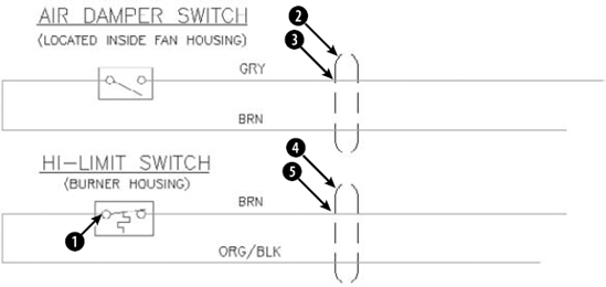
ab18-04.dwgin yourAutoCAD Biblefolder. This is a portion of an electrical schematic, as shown in Figure 18.11. Object Snap should be on. Set running object snaps for Endpoint, Midpoint, Quadrant, and Intersection.Choose Home tab
Use the Quadrant object snap to pick the left quadrant of the left circle in the switch, at
Use a selection window to select the air damper switch. (The objects are currently on the Object layer, which is red with a continuous linetype.) Choose Home tab
Choose Home tab
Use a selection window to select the top conduit symbol at
Use a selection window to select the bottom conduit at
Save your drawing. Choose Application Button
Choose View tab
Check the Layer drop-down list. A new layer,
Object, is the layer that the original objects were on.In the right pane of the DesignCenter, double-click
top conduit. In the Insert dialog box, click OK. Follow the prompts to insert the file anywhere in the drawing, using a scale factor of 3. Again, the object retains its explicitly set properties of green color and Hidden2 linetype but is listed as being on layer 0. Click the Layer drop-down list to see that the Conduit layer has been added to the drawing.Click Home tab
In the DesignCenter's right pane, double-click
ad switch. In the Insert dialog box, click OK. Follow the prompts to insert the file anywhere in the drawing, using a scale factor of 3. The block (whose objects were created on the Object layer and whose properties were set to ByBlock) takes on the current color of Cyan and is listed on layer 0.Choose Home tab
In the DesignCenter, double-click
bot conduit. In the Insert dialog box, click OK. Follow the prompts to insert the file anywhere in the drawing, using a scale factor of 3. The block, whose original objects were on layer 0, has the properties of layer Green and is listed on layer Green.Click the DesignCenter's Close button to close the DesignCenter. Don't save this new drawing.
When you explode blocks that were created on layer 0 or with BYBLOCK objects, the objects return to their original status and appear black/white with a continuous linetype and default lineweight again. If you insert a block with different X and Y scales, the command does its best to create objects based on their new shapes. For example, if you have a block that includes a circle and insert it with an X scale of 1 and a Y scale of 2, you see an ellipse. Therefore, when you explode the block, you get an ellipse from what used to be a circle.
Note
When you explode an annotative block, you get the components of the current scale presentation only. The components are not annotative.
The XPLODE command is a version of the EXPLODE command that you can use to control the final layer, color, and linetype of the objects. If you select more than one object, you can set the properties for all the objects that you select at once (that is, globally) or for each object individually.
To xplode an object, type xplode
At the Enter an option [All/Color/LAyer/LType/LWeight/Inherit from parent block/Explode] <Explode>: prompt, choose whether you want to specify color, layer, linetype, lineweight, or all four. If you are using AutoCAD, the Color option allows you to specify true colors using the RGB system or a color from a color book. (See Chapter 11 for more information.) The Inherit from Parent Block option works only for blocks created on layer 0 whose color and linetype were also set to ByBlock. These ByBlock objects then retain their color and linetype after you explode them.
Xplode cannot explode blocks whose X and Y scale factors have unequal absolute values. That means an X scale of 1 and a Y scale of −1 is okay, but not an X scale of 2 and a Y scale of −3.
Note
The drawing that you need for the following exercise on exploding and xploding blocks, ab18-e.dwg, is in the Drawings folder on the DVD.
STEPS: Exploding and Xploding Blocks
Open
ab18-e.dwgfrom the DVD.Save the file as
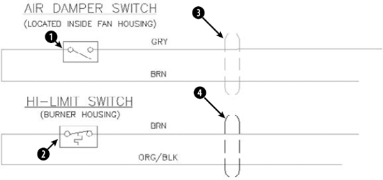
ab18-05.dwgin yourAutoCAD Biblefolder. This is the same electrical schematic used in the previous exercise, except that the objects are now blocks that have been inserted (see Figure 18.12). Object Snap should be on. Set running object snaps for Endpoint, Midpoint, Quadrant, and Intersection. The current layer is Object.
Choose Undo from the Quick Access toolbar.
Type xplode
Choose the
hi-limitswitch atType xplode
Select objects:
Choose the conduits atand.End selection. 2 objects found. Xplode Individually/<Globally>:to accept the default. Enter an option [All/Color/LAyer/LType/LWeight/Inherit from parent block/Explode] <Explode>:Right-click and choose All. New Color [Truecolor/Colorbook] <BYLAYER>:Enter new linetype name for exploded objects <BYLAYER>:Enter new lineweight < >:Enter new layer name for exploded objects <OBJECT>:conduitObjects exploded with color of BYLAYER, linetype of BYLAYER, and layer conduit.Save your drawing.
Blocks can be complex objects. You may need to add, remove, or change a component of a block. You can also update or substitute blocks. Here are a few additional points that can help you to work with blocks.
If you double-click a block, you open the Edit Block Definition dialog box. Choose the block from the Block to Create or Edit list and click OK to open the Block Editor. The Block Editor opens. I explain the Block Editor in detail later in this chapter in connection with dynamic blocks. However, you can use the Block Editor to edit all blocks, not just dynamic ones. Make the changes you want.
To a certain extent, you can use grip editing with blocks. By default, when you select a block, only one grip — at the base point — is displayed. However, you can show the grips of all the objects by choosing Application Button
As a general rule, you don't want to enable grips for blocks when working with complex blocks. However, you can turn them on to use grips to mirror, rotate, move, or scale the block if you want to use the grip of a component object as a base point for the edit.
As I mentioned earlier in the chapter, when you redefine a block, all instances of that block are automatically updated. However, if you inserted a file to use as a block in a drawing and then changed that file, your current drawing has no way of knowing of the change in that drawing file. (Instead, use an external reference to solve this problem. See Chapter 19 for more on external references.)
To update a block that came from inserting an entire file, you can reinsert the file. Follow these steps:
Choose Home tab
Click Browse.
Choose the file that you've changed, and click Open. (You must locate the actual file rather than choose the block of the same name that already exists in the drawing.)
A message asks whether you want to redefine the block because that block already exists in the drawing. Choose Redefine Block.
Press Esc to avoid actually inserting a new copy of the block.
The drawing updates all the instances of the block with the new file. You can also use the DesignCenter to insert and update blocks.
Tip
You can update a block definition in your current drawing to match a block on a tool palette by right-clicking the block tool on the tool palette and clicking Redefine. All instances of the block are redefined to match the tool on the tool palette. (The block on the tool palette must be in the current drawing, not an external drawing.)
You can substitute a different file as the basis for blocks in your drawing. There are three reasons for doing this:
If you have many instances of complex blocks, you may find that regen times are slow. You can create a simple block, WBLOCK it, and substitute it for the original blocks until plotting time.
You can create more than one version of a drawing — for example, an office layout with various kinds of desks. You can create the drawing with one type of desk, inserting files of the desks. Substitute a file of another type of desk, and you have a new office layout design.
Another common reason to substitute blocks is when your company switches to a different standard for a part.
To substitute blocks, follow these steps:
Type -insert
Type blockname=filename where blockname is the name of the block and filename is the name of the file. (If the file is not in the support file search path, type the entire path.) Press Enter.
Note
To place a folder in the support file search path, choose Application Button
A message tells you that the block with this name already exists, and asks whether you want to redefine it. Type y
Press Esc to avoid actually inserting a new copy of the new file.
The file that you inserted replaces the current blocks.
Note
The Express Tools command BLOCKREPLACE (choose Express Tools tab
Usually when you insert a file into a drawing, the block name and filename are the same. Likewise, when you WBLOCK a block, you usually name the file with the name of the block. Be aware that when you use block substitution, you have a block in your drawing that is the same as a file of a different name. For example, if you have a block in your drawing called smalldesk and substitute a file called bigdesk, you now have a block called smalldesk that is actually the same as the file bigdesk. This can become confusing, so use block substitution with care.
Note
Wb.zip unzips to three programs that create a list of blocks in your drawing, and writes them to separate drawing files. Display the list of blocks and open selected drawings from the list; after you modify them, update those drawings as blocks in your current drawing. WBLOCKM also writes all the blocks in your drawing to a folder that you specify. Look in SoftwareChapter 18Wb. These programs work with AutoCAD only. MPE-arch is a library of mechanical, plumbing, and electrical symbols for architectural drawings, mostly lights and outlets. Mpe.dwg contains all the symbols and can be used as a legend. Look in SoftwareChapter 18Mpe-arch. North is a collection of North symbols for architectural drawings. Look in SoftwareChapter 18North.
You probably have multiple similar blocks that you store and use on a regular basis. Moreover, you might insert these blocks at various scales and rotation angles. For example, you could have several sizes of doors that you insert at various angles, sometimes right-opening and sometimes left-opening. Dynamic blocks are blocks that contain intelligence and flexibility so that you can insert them in many variations. Thus, they can significantly reduce the number of blocks in your block library.
Note
Dynamic blocks support both geometric and block parametric constraints. You can convert dimensional parametric constraints to block parametric constraints by choosing Block Editor tab
Dynamic blocks let you specify the types and amounts of variations for each block. You create (author) dynamic blocks in the Block Editor. You can use one of two systems to accomplish your goal. Each system has its strengths; use the system that most easily gives you the results you need.
Note
You can control many of the colors used in the Block Editor as well as other display features. Click the dialog box launcher arrow at the right end of the Block Editor's Manage panel to open the Block Editor Settings dialog box.
This section describes action-based parameters. Action-based parameters allow for complex systems of flexibility. (I cover parametric constraints, which are different, including geometric and dimensional constraints, in Chapter 10.) For a block to be dynamic, it must include at least one parameter. A parameter usually has an associated action.
Parameters define the special properties of the dynamic block, including locations, distances, and angles. Parameters can also constrain the values within which the parameter can function. An action specifies how a block uses its associated parameter to change in some way.
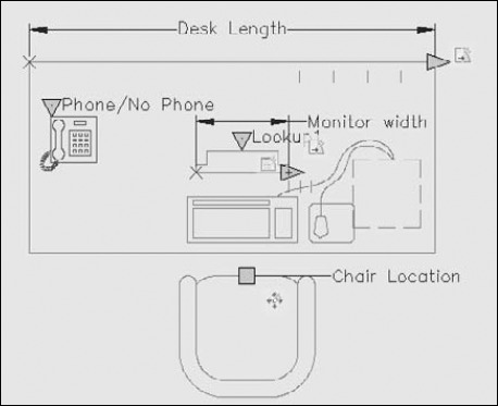
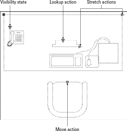
For example, you may want to move one component of a block independently of the block, such as the chair in a block containing a desk and a chair. To accomplish this, you add a point parameter that specifies a point on the chair. You then add a move action that allows you to move the chair from that point. Figure 18.13 shows a desk and a chair block that includes the following dynamic components:
The desk has a distance parameter with a stretch action. Therefore, you can stretch the desk without affecting the chair. You would use this type of action if you have several sizes of desks that you need to include in your drawing.
The chair contains a point parameter with a move action. As a result, you can move the chair independently of the rest of the block. If you stretch the desk, you might want to move the chair so that it remains centered in front of the desk, or you might simply want to move the chair farther away from the desk.
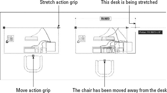
Figure 18.13. This dynamic block contains components that enable you to stretch the desk's length and move the chair.
If you open a dynamic block in a pre-2006 release of AutoCAD or AutoCAD LT, you see the last current view of the block. You cannot use the dynamic features of the block, but you can edit it as a regular block. The block is assigned a name, such as U2.
To change the background color of the Block Editor, choose Application Button
Because defining a dynamic block takes some time — although simpler dynamic blocks are not very time-consuming to set up — the most common use for dynamic blocks is to create a block library. Normally, you define your dynamic blocks and save them for future use in your drawings. In other words, unless you need to insert a new block many times in several variations in a drawing, you won't create dynamic blocks for the current drawing on which you're working.
A block library can have two configurations:
One block per drawing. You save each block in its own drawing. Use the BASE command to specify the origin of the drawing, which is usually on an object snap somewhere on the block. (I explain the BASE command in the "Saving blocks as files" section earlier in this chapter.) You use the INSERT command to insert the drawing, thereby inserting its block.
Many blocks per drawing. You put a number of (usually) related blocks in a drawing. To insert the block, you use the DesignCenter to locate the drawing and find the individual block that you want. (See the section "Using the DesignCenter" earlier in the chapter for information on inserting blocks with the DesignCenter.)
The first part of the process of creating dynamic blocks is to define the block. I explain the details in the next few sections, but here I provide an overview of the workflow:
In your block library drawing or in a new drawing, create the block.
Choose Home tab
Add parameters and associated actions, or geometric parametric constraints.
Save the block definition in the Block Editor.
Close the Block Editor.
If the drawing will contain just this block, use the BASE command to set the drawing origin where you want the insertion point to be, usually somewhere on the block.
Save the drawing.
You may want to follow this process for any number of blocks. When your blocks are defined, do the following to insert your dynamic blocks:
In your current drawing, either use the INSERT command to insert the drawing containing the block, or use the DesignCenter to choose the block from within the drawing.
Select the block to see its special grips. These grips show you where you can modify the block.
Usually, you click and drag a grip. Some dynamic block parameters involve choosing a visibility or option from a drop-down list or table.
Before you start defining your block, you need to decide the types of variations that you want the block to have. You build flexibility into your blocks with a combination of parameters and actions. Table 18.2 lists the parameters, the actions that you can add to each parameter, and a description of the uses for the parameters and actions on the specified component of the dynamic block.
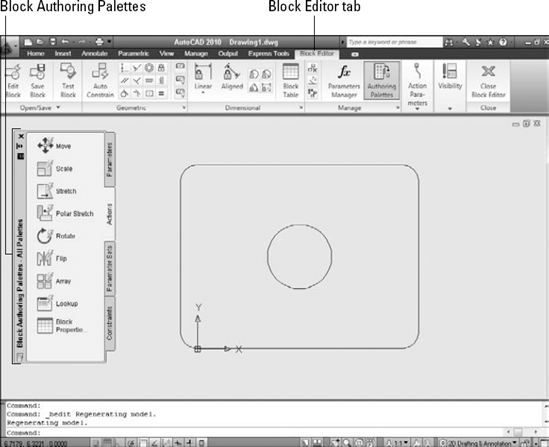
Table 18.2. Dynamic Block Parameters and Actions
Available Actions | Uses | |
|---|---|---|
Point | Move, Stretch | Move or stretch from that point (X,Y coordinate). |
Linear | Move, Scale, Stretch, Array | Move, scale, stretch, or array along the line between two points. |
Polar | Move, Scale, Stretch, Polar Stretch, Array | Move, scale, stretch, stretch at an angle, or array along the line between two points and at the specified angle. |
XY | Move, Scale, Stretch, Array | Move, scale, stretch, or array at the specified X and Y distance. |
Rotation | Rotate | Rotate at the specified angle. |
Alignment | None | Align the entire block with other objects. You can align perpendicular or tangent to other objects. No action is required. |
Flip | Flip | Flip along a reflection line. Flipping is like mirroring without retaining the original objects. |
Visibility | None | Control the visibility of components in the block. No action is required. See the section "Adding visibility parameters" later in this chapter. |
Lookup | Lookup | Choose a custom property from a list or table that you define. See the section "Adding lookup parameters and actions" later in this chapter. |
Basepoint | None | Define a base point for the dynamic block. |
To create a dynamic block, you start by adding a parameter. Click the parameter that you want from the Parameters tab of the Block Authoring Palettes window. Each parameter prompts you for the information it needs. For example, the linear parameter responds with the Specify start point or [Name/Label/Chain/Description/Base/Palette/Value set]: prompt. When you specify the start point, you get a prompt for the endpoint. The flip parameter prompts you for a reflection line, which is like a mirror line.
The options for each parameter are fairly similar. Here's how to use the options:
Name. You can change the name of the parameter. The name appears in the Properties palette when you select the parameter. However, you may find it confusing to change the name, because the name clearly denotes which parameter the block uses. On the other hand, if you have more than one of the same type of action, such as two stretch actions, renaming the actions to identify what they apply to can eliminate confusion. For example, you could have two Move actions, "Move table" and "Move chair."
Label. The label appears in the Properties palette, but also next to the block when you have the Block Editor open. Change the label to suit your needs. For example, the linear parameter uses a label of "Distance." You might want to change that to Length, Width, or even something more specific.
Chain. Sometimes, you might want one action to cause more than one change in a block. To do this, you can chain parameters. As a result, activating one parameter's actions causes the secondary parameter's action to occur. The primary parameter must have an action whose selection set includes the secondary parameter in addition to any other objects it will act on. (If the action is a stretch action, the stretch frame also needs to include the secondary parameter.) You must then set the secondary parameter's Chain property to Yes.
Description. You can add a description to a parameter. This description displays in the Properties palette when you select the parameter in the Block Editor.
Note
If you add a description, it appears as a tooltip when you select the inserted dynamic block in your drawing and hover the cursor over the parameter's grip. You could use this feature to provide a brief description of the type of parameter or instructions on how to use it.
Base. Creates a base point parameter, which sets a base point for the block.
Palette. By default, displays parameter labels in the Properties palette when you select the block reference in a drawing. Change to No if you don't want to display the labels.
Value set. You can constrain the available values for your block's size, either as increments (for example, from 3 feet to 7 feet in 6-inch increments) or by providing a list (for example, only 36″, 40″, and 42″). This option prompts you to choose either the increment or the list method, and then prompts you for values. You can also specify a value set later in the Properties palette.
When you are finished using the options or have specified the necessary coordinates (such as a start point and endpoint for a linear parameter), the Specify label location: prompt appears. Pick a point to place the label for the parameter.
An exclamation point now appears next to the parameter. This exclamation point alerts you that you have not yet added an action to the parameter. Most parameters require an action to function properly. Figure 18.15 shows a chair with a linear parameter.
You can use the grips of the parameters as insertion points when you insert the dynamic block. During insertion, you press Ctrl to cycle among the grips if their Cycling property is set to Yes. To check, select a grip, open the Properties palette, and look for the Cycling property. You can specify the order of the cycling. Select a grip, right-click, and choose Insertion Cycling to open the Insertion Cycling Order dialog box, where you can turn cycling on or off for each grip and move the grips up and down in the order of the list.
When you have placed a parameter, you're ready to add an associated action. Table 18.2 lists which actions you can associate with your parameter. Click the Actions tab of the Block Authoring Palettes window, as shown in Figure 18.16.
Sometimes, the parameter that you want to use has more grips than you need. For example, if you use a linear parameter, you end up with two grips, one at each end of the length that you define. However, you might want to stretch only in one direction; in this case, you need to have only one grip. To remove the extra grip, select the parameter, right-click, and choose Grip Display
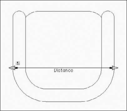
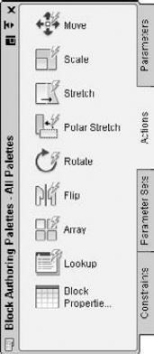
Figure 18.16. Use the Actions tab of the Block Authoring Palettes window to associate an action with a parameter.
Tip
Why would you use the linear parameter (rather than a point parameter) when you want to add a stretch action? When you stretch the inserted dynamic block, if you have Dynamic Input turned on, you see a linear tooltip that allows you to enter a total length. You can set the total length in the Properties palette, but that isn't nearly as convenient. Also, a point parameter doesn't offer the Value Set option, which lets you constrain sizes.
To add an action, choose an appropriate action for your parameter. At the Select parameter: prompt, select the parameter. Remember that you always apply an action to a parameter, rather than to an object. However, as part of the process, you specify a selection set for the action, which means selecting the object or objects. Note that you can add more than one action to a parameter.
Warning
Be sure to select the actual parameter, and not the object or the grip. An easy way to select the parameter is to click its label.
The next prompts depend on the action that you choose and on the parameter to which you're attaching the action. Table 18.3 explains some of the prompt options that you find for commonly used actions.
Table 18.3. Action Prompt Options
Note
Defining the stretch frame for a stretch action is similar to specifying a crossing selection window in the STRETCH command, except that you can create the stretch frame from left to right. For example, objects within the frame are moved, and objects that cross the frame are stretched. However, you also select objects for a stretch action. If objects are in the stretch frame but not in the selection set, they are not stretched or moved. If objects are outside the frame, but are in the selection set, they are moved. After you select objects, you can select or deselect individual objects to add them to, or subtract them from, the selection set.
When you complete your answers for the prompts, AutoCAD displays an icon for the action. As you add more parameters and actions to a block, you may sometimes need to know which parameter goes with which action. To find out, hover the cursor over an action's icon to highlight its parameter.
Warning
If the exclamation point doesn't disappear after you add an action, the action was not successfully added! Undo the last command (BACTIONTOOL) and try again. Usually the problem involves selecting the proper parts of the parameter and correctly selecting the applicable objects. Reducing the number of grips may also solve this problem. Select the parameter, right-click, and choose Grip Display.
You can modify the action to multiply the parameter value by a factor or change the parameter angle. To do so, select the action's icon and display the Properties palette (Ctrl+1). Then do one of the following:
Distance Multiplier. Click next to the Distance Multiplier item in the Properties palette and enter another value to multiply the parameter by that factor. For example, you can multiply a stretch by a factor of .5. If you want to keep a circle centered inside a rectangle that you're moving or stretching, use a .5 multiplier so that the circle moves or stretches half of the distance of the rectangle, thereby remaining centered.
Angle Offset. Click next to the Angle Offset item in the Properties palette and enter an angle to offset the parameter angle by that angle. For example, you can increase an angle by 90 degrees. This allows you to move the cursor to the right (0 degrees) and stretch an object in the 90-degree direction.
Visibility parameters enable you to turn the visibility of a block component on and off when you insert it. You can use visibility parameters either with other action-based parameters, or with geometric and dimension parametric constraints. You can define multiple named visibility states, thereby creating many variations of visibility or invisibility. Visibility parameters are a very powerful way to add flexibility to a block and to reduce the number of similar blocks that you store. You can add only one visibility parameter per block. You can use visibility parameters in two ways:
Make one component visible or invisible. You can choose to display or not display one component. For example, if you have a telephone on a desk, you can display or not display the telephone.
Switch among multiple components. You can include variations of a component, and cycle among them during insertion. For example, you can have three types of telephones (such as single-line, two-line, and multiple-line), all in the same location, with one on top of the other. When inserting the block, you can choose which telephone to display.
To add a visibility parameter, follow these steps:
Open the Block Editor in a drawing that contains the components that you need. If you want to switch among multiple components, place them on top of each other.
Choose Visibility from the Parameters tab of the Block Authoring Palettes window, and place it near the components. Before placing the parameter, you may want to use the Label option to change the label.

Click the default visibility state (VisibilityState0) to select it. Enter a new name for your first state and press Enter. The name should relate to what the state will display. In the telephone example, you might use
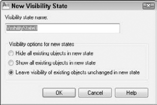
telephoneorsingle-lineas the state.Click New to open the New Visibility State dialog box, as shown in Figure 18.18.
Enter a new visibility state name. In the telephone example, you might use
no telephoneortwo-line. To leave the visibility of existing objects unchanged, use the default option, Leave Visibility of Existing Objects Unchanged in New State. If you want the new state to hide all objects, choose Hide All Existing Objects in New State. To display all objects, choose Show All Existing Objects in New State. Whichever option you choose, you can change the visibility of individual objects for each state afterwards. Click OK.If you need more visibility states, repeat Steps 5 and 6 until you're done.
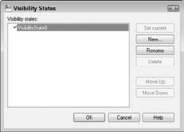
Click OK to close the Visibility States dialog box and return to the Block Editor.


Note
If you need to select an object that's invisible, choose Block Editor tab

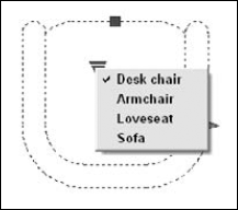
When you insert the dynamic block and select it, you see a down arrow. Click the arrow to display the list of visibility states. Choose the state that you want.
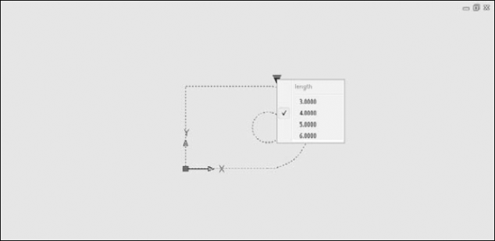
A lookup parameter/action combination creates a table that pairs labels with values. For example, you might have a desk that comes in three sizes. You can create this desk and use the Value Set option to create a list of three sizes: 4 feet, 5 feet, and 6 feet. You can then create labels that say 4' desk, 5' desk, and 6' desk. When you insert the desk, you can choose the label that you want from a drop-down list; the desk automatically stretches to the proper size. You don't need to use the Value Set option, because you specify values in the lookup table. Later in this chapter, I discuss Block Tables, which are another way to create a list of size variations. If you are using parametric constraints, you use a Block Table, rather than a lookup table.
Lookup tables are great when you want preset sizes for a block. When you insert the block, you don't even have to think about exact measurements; you just choose from a drop-down list, as shown in Figure 18.19.
To create a lookup parameter and action, follow these steps:
In the Block Editor, add a parameter and action that you will use as the basis for the Lookup parameter and action. For example, add a linear parameter and a stretch action. If you add a value set (list or increment), the measurements will be available in advance when you create the lookup table.
From the Parameters tab of the Block Authoring Palettes window, add a lookup parameter.
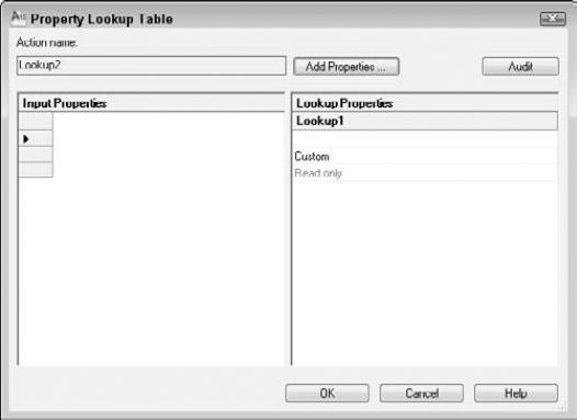
From the Actions tab, add a lookup action. At the prompt, select the lookup parameter. The Property Lookup Table dialog box opens, as shown in Figure 18.20.
Click the Add Properties button, choose the parameter that you want to work with (for example, the linear parameter), and click OK. You return to the Property Lookup Table dialog box.
If you have values from a value set, you can see them by clicking the first row in the Input Properties side of the dialog box. A drop-down arrow appears. Choose the first value. If you don't have a value set, click the Add Properties button, choose the parameter you want, and click OK. Click on the Input Properties side, and choose a value from the drop-down list that appears. Click the same row on the Lookup Properties side of the dialog box and enter the label that corresponds with the value. Then click the next row, choose the next value, and enter the next label. Continue until you're done.
If the lower-right cell in the dialog box says Read Only, click it so that it changes to read Allow Reverse Lookup. (To do this, all the rows in the table must be unique.) You need to use this option in order to choose a value from a drop-down list of labels when you insert the block.
Click Block Editor tab
Now each value in the lookup table is associated with the labels that you entered. When you insert the dynamic block and select it, click the down arrow and choose from the options that drop down.
Tip
To edit the lookup action, right-click it and choose Display Lookup Table to open the Property Lookup Table dialog box. There you can make your changes.
The Parameter Sets tab of the Block Authoring Palettes window contains a number of ready-made parameter-action combinations that you can use. These sets are great for quick creation of dynamic blocks that are not complex. Hover the cursor over any parameter set to see a tooltip explaining the set's functioning.
When you place a parameter set, you see an exclamation point, because you have not yet selected the objects for the action. Right-click the action icon and choose Action Selection Set
Tip
You can edit these parameter sets and create new ones. To create a new one, right-click the parameter set on the Parameter Sets tab and choose Copy. Then right-click the tab itself and choose Paste. To change a parameter set, right-click a parameter set and choose Properties. Then change the settings in the Tool Properties dialog box. To add an action, click the Actions item, and then click the Ellipsis button to open the Add Actions dialog box.
Parametric constraints allow you to control the geometric and dimensional relationships among objects. I cover parametric constraints in full in Chapter 10. This discussion assumes that you have read that chapter.
Note
Parametric constraints are new for AutoCAD 2010. You can't create them in AutoCAD LT, but if they are in a drawing that you open, you can use them.
Warning
Dynamic block parameters and actions, just previously described, and parametric constraints have some overlap in their capabilities. In most cases, you should use one or the other, but not both, for any dynamic block. Combining the parameters-actions feature with the parametric constraints feature can create undesirable results, because constraints may prevent an action from functioning the way you want it to, or may allow a valid yet unintended result. However, visibility, alignment, and base point parameters should not cause a problem when you use them along with parametric constraints because they don't change the geometry of the block itself.
White. Unconstrained
Blue. Partially constrained
Magenta. Fully constrained
Red. Improperly constrained
To change the colors for each category, click the dialog box launcher arrow at the right end of the Manage panel to open the Block Editor Settings dialog box.
Tip
You can add a Fix geometric constraint to fix the block's base point to a specific point. This ensures that the block changes relative to that fix point. Sometimes, this is all you need to add to the auto-constraining process to make a block fully constrained.
Add the geometric constraints you need from the Block Editor's Geometric panel (or the Constraints tab of the Block Authoring palette), whether manually or by auto-constraining; then move on to dimensional constraints from the Dimensional panel. When you add dimensional constraints inside the Block Editor, you get a prompt for the number of grips. By including one or more grips, the dimensional constraint allows you to modify the block in your drawing, just like grips for actions (discussed earlier in this chapter). In this way, a linear constraint can replace a linear parameter/stretch action combination.
To restrict allowable values, you can add a value set to a dimensional constraint. (I cover value sets earlier in this chapter.) Select the constraint, display the Properties palette (Ctrl+1), and use the Value Set section.
A Block Table allows you to specify defined sizes for dimensional constraints and select those sizes from a drop-down list when you modify the dynamic block. A Block Table is similar to a lookup table, covered earlier in this chapter, but has some differences. You cannot use a Block Table with action-based parameters; instead, use a lookup table.
Note
Block Tables are new for AutoCAD 2010. Block Tables let you create preset sizes for dimensional constraints.
A dynamic block can have only one Block Table. When you use the Block Table for one dimensional constraint, it functions like a lookup table, allowing you to choose a size from the drop-down list. However, the Block Table can include more than one dimensional constraint; in this case, you can create combinations of sizes. For example, you might allow a rectangle with two dimensional constraints to be 2 × 3, 3 × 4, or 4 × 5. In this situation, you could not choose 2 × 5 from the drop-down list, because that combination is not in the Block Table. However, you can allow other values, but they wouldn't be available from the drop-down list.
Specify parameter location or [Palette]:Specify a location where the drop-down list will appear. Use the Palette option and choose Yes or No to specify whether you want to display the Block Table in the Properties palette. Enter number of grips [0/1] <1>:Enter1to display a down-facing triangle, which will open the drop-down list of values. Enter0to hide the drop-down list.
Enter the desired values in the cells of the table. Remember that if you chose more than one constraint, the drop-down list will only allow the combinations that you enter. Figure 18.21 shows a table with two dimensional constraints (d1 and d2) applied to a rectangle, and three size options.
Note
If you created a value set for a dimensional constraint, you cannot enter values that are not specified in the value set.
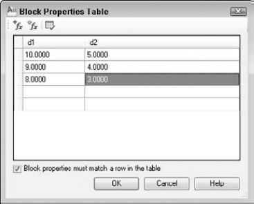
If the Block Properties Must Match a Row in the Table check box is checked, you can't modify the dynamic block to sizes not in the table. If you uncheck this check box, only sizes in the table will appear in the drop-down list, but you will be able to drag the block to sizes not listed.
Tip
To make a copy of the block, choose Block Editor tab
Note
The ability to test a block without exiting the Block Editor is new for AutoCAD 2010 and AutoCAD LT 2010. This feature makes testing a block quicker and simpler.
A new Test Block Window opens. Select the block and try out its dynamic features. For more information about using a dynamic block, see the "Inserting and modifying dynamic blocks" section later in this chapter. When you are done, click the Close Test Block Window button on the ribbon to return to the regular Block Editor window.
To close the Block Editor, choose Block Editor tab
If you want to put the base point for the block somewhere on the block, use the BASE command. Then save your drawing.
You insert a dynamic block in the same way that you insert a regular block: by using the Insert dialog box or the DesignCenter. For more information, see "Inserting Blocks and Files into Drawings" earlier in this chapter.
During insertion, you can press Ctrl to cycle among the grips if their Cycling property is set to Yes. Each time you press Ctrl, the cursor moves to another grip on the block. Also, before you specify the insertion point, you can open the Properties palette and specify values, such as the distance value of a length parameter.
To use the dynamic features of the block, first select the block. You see turquoise dynamic block grips, depending on the type of action. You click and drag these grips in the same way that you do for regular grips; the difference is that the resulting modification is controlled by the parameters-actions or the parametric constraints that you defined. If you have created a value set, you see vertical lines at the available lengths, as shown to the right of the cursor in Figure 18.22. Lookup and visibility actions, as well as Block Tables, have a down arrow so that you can open a drop-down list and choose a lookup table, visibility state, or table row, respectively.
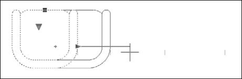
Figure 18.22. This block can be a chair, loveseat, or sofa. The faint vertical lines indicate the available lengths as you drag.
Note
The drawing that you need for the following exercise on creating and inserting dynamic blocks using action-based parameters, ab18-f.dwg, is in the Drawings folder on the DVD. Following this exercise is one on creating and inserting dynamic blocks using parametric constraints and a Block Table.
STEPS: Creating and Inserting Dynamic Blocks Using Action-Based Parameters
Open
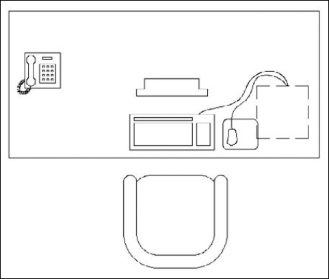
ab18-f.dwgfrom the DVD. This is a set of office furniture, as shown in Figure 18.23.Save the drawing as
ab18-06.dwgin yourAutoCAD Biblefolder. Set an Endpoint running object snap.Hover the cursor over any part of the drawing. You can see that it is all one block, called DeskSet.
Double-click the block. In the Edit Block Definition dialog box, choose
DeskSetand click OK. The Block Editor opens with the desk set (including a desk, armchair, computer, monitor, and phone) displayed. Inside the Block Editor, you work with the individual components of the DeskSet block. The Block Authoring Palettes window also opens.You want to be able to move the armchair separately from the rest of the block. To add a point parameter to the chair, click the Parameters tab of the Block Authoring Palettes window and choose Point.
Follow these prompts:
Specify parameter location or [Name/Label/Chain/Description/Palette]:
Right-click and choose Label. Enter position property label <Position>:Chair LocationSpecify parameter location or [Name/Label/Chain/Description/Palette]:Pick the endpoint at the middle of the front of the chair. Specify label location:Pick a location for the Chair Location label.To add a Move action to the point parameter, click the Actions tab and choose Move. Follow the prompts:
Select parameter:
Select the point parameter by clicking its label. Specify selection set for action. Select objects:Select all the objects that make up the chair. (In this instance, it doesn't make any difference whether or not you include the actual parameter in the selection set.)Select objects:To add a linear parameter to the desk, click the Parameters tab and choose Linear. Follow the prompts:
Specify start point or [Name/Label/Chain/Description/Base/Palette/Value set]:
Right-click and choose Label. Enter distance property label <Distance>:Desk lengthSpecify start point or [Name/Label/Chain/Description/Base/Palette/Value set]:Right-click and choose Value Set.Enter distance value set type [None/List/Increment] <None> :
Right-click and choose Increment. Enter distance increment:6Enter minimum distance:48Enter maximum distance:72Specify start point or [Name/Label/Chain/Description/Base/Palette/Value set]:Choose the endpoint at the upper-left corner of the desk. Specify endpoint:Choose the endpoint at the upper-right corner of the desk. Specify label location:Pick a location above the desk.We only want the right grip for the linear parameter. This makes sure that the desk can only be stretched toward the right. Select the linear parameter. Right-click and choose Grip Display
Click the Actions tab and choose Stretch. Follow the prompts:
Select parameter:
Select the linear parameter by clicking its label. Specify parameter point to associate with action or enter [sTart point/Second point] <Start>:Pass the cursor over the right grip and click. Specify first corner of stretch frame or [CPolygon]:Click atin Figure 18.24. Specify opposite corner:Click at. Specify objects to stretch. Select objects:Click close to but not on top of. Specify opposite corner:Click close to but not on top of.The command line should show 52 found. Select objects:The block should look like Figure 18.24.
To allow for various sizes of monitors, click the Parameters tab and choose Linear. Right-click and choose the Label option. Type Monitor width
At the next two prompts, pick points
You can also create a value set in the Properties palette. Select the
Monitor widthparameter and open the Properties palette (Ctrl+1). In the Value Set section, choose List from theDist Typedrop-down list. Next to theDist Value Listitem, click the Ellipsis (...) button to open the Add Distance Value dialog box. The current width is already there. In the Distances to Add text box, type 18-1/2With the linear parameter still selected, in the Properties palette, change the value of the Number of Grips item (in the Misc section) to 1. Close or minimize the Properties palette.
Click the Actions tab in the Block Authoring Palettes window and choose Stretch. At the
Select parameter:prompt, select the linear parameter that you just created. At the next prompt, click the right parameter point. To specify the stretch frame, pickYou want to create a lookup parameter for the monitor. On the Parameters tab, choose Lookup and pick a location on the monitor. On the Actions tab, choose Lookup. Select the lookup parameter. The Property Lookup Table dialog box opens.
Click the Add Properties button. In the Add Parameter Properties dialog box, choose the
Linear 1parameter and click OK. Back in the Property Lookup Table dialog box, click the first row on the Input Properties side, below the Monitor width heading, and choose the first measurement from the drop-down list. In the same row on the Lookup Properties side, type 15″ monitor. (Note that monitors are measured diagonally, so the horizontal width of a 15″ monitor is not 15″.) In the second row on the Input Properties side, choose the second measurement and enter 17″ monitor on the right. In the third row on the left, choose the last measurement and enter 19″ monitor on the right.Click the Read Only cell; it changes to read Allow Reverse Lookup. The Property Lookup Table dialog box should have the rows shown below. Click OK.
1'-4 1/2″             15″ monitor
1'-6 1/2″              17″ monitor
1'-8 1/2″              19″ monitor
Because some people may not have a land-line phone, we want to create a visibility parameter and action for the phone. On the Parameters tab, choose Visibility. Follow the prompts:
Specify parameter location or [Name/Label/Description/Palette]:
Right-click and choose Label. Enter visibility property label <Visibility>:Phone/No PhoneSpecify parameter location or [Name/Label/Description/Palette]:Pick a location near the phone.


Open a new drawing based on the default template or any template that you usually use. Open the DesignCenter. In the Open Drawings pane, browse to, and double-click,
ab18-06.dwg. Click Blocks. Drag the DeskSet block from the right side of the DesignCenter to your drawing. Close or minimize the DesignCenter.Note
If you create a block inside a drawing and then make it dynamic, you need to use the DesignCenter to insert it. If you try to insert the entire drawing, you see only a regular block. However, if you don't create a block in the source drawing and create the dynamic block in the Block Editor without ever creating and naming a block, you can use the INSERT command to insert the entire drawing and use the dynamic features of the block.
Choose View tab
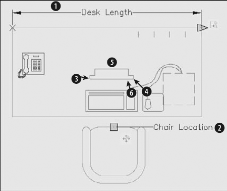
Select the DeskSet block. It should look like Figure 18.26.
Click the desk's stretch grip and stretch the desk one vertical line to the left to make it 6 inches shorter. The computer moves with the desk.
Click the armchair's move grip and move the chair to the left so that it is still centered in front of the computer.
Click the monitor's lookup grip and choose
19″ monitorfrom the drop-down list. The monitor becomes wider.Click the phone's visibility grip and choose
No phonefrom the drop-down list. The phone disappears.Continue to experiment with the grips to see all the possible variations. You do not need to save this drawing.
Note
The drawing that you need for the following exercise on creating and inserting dynamic blocks using parametric constraints and a Block Table, ab18-g.dwg, is in the Drawings folder on the DVD.
STEPS: Creating and Inserting Dynamic Blocks Using Parametric Constraints and a Block Table
Open
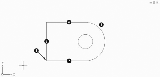
ab18-g.dwgfrom the DVD. This is a sheet metal plate, similar to the one used in the Chapter 10 exercise on parametric constraints, as shown in Figure 18.27.Save it as
ab18-07.dwgin yourAutoCAD Biblefolder. Set a running object snap for Endpoint.The goal is to create a block that can be four sizes; however, the central hole's diameter should remain unchanged. To create the blocks, select all the objects, and choose Home tab
In the Block Definition dialog box, enter ab18-g1 for the block name. In the Base Point section, the Specify On-Screen check box should be checked; the other Specify-On-Screen check boxes should not be checked. Check the Open in Block Editor check box and click OK.
At the
Specify insertion base point:prompt, pick the endpoint atChoose Block Editor tab
As you stretch the block, the three straight sides need to remain equal. You only need to specify two of the sides. Choose Block Editor tab
As you stretch the block, you don't want the base point to move, so choose Block Editor tab
To keep the inner circle unchanged, add a diameter parameter. Choose Block Editor tab
Select arc or circle:
Pick the inner circle. Specify dimension line location:Pick a location to the left of the circle. Enter value or name and value <dia1=1.5000>:Enter number of grips [0/1/2] <2>:0(You enter 0 because you don't need to change the diameter.)To add a linear dimensional constraint, choose Block Editor tab
Specify first constraint point or [Object] <Object>:
Select object:Pick the top horizontal line at. Specify dimension line location:Pick a location above the line. Enter value or name and value <d1=4.0000>:Enter number of grips [0/1/2] <1>:0(You would need a grip if you wanted to drag the block, but you will use the Block Table feature instead.)To change the name of the linear constraint, select it and open the Properties palette (Ctrl+1). In the Constraint section, change the Name value to length.


Choose Block Editor tab

Choose the various sizes to see the result. The inner circle should remain concentric with the outer arc but should not change size. The three sides should always be the same length.
Click Close Test Block Window to return to the Block Editor.
Click Block Editor tab
Save your drawing.
You can insert objects by copying them from other drawings and pasting them into your current drawing or using the drag-and-drop feature. You may be able to insert objects in this way without creating blocks.
You're probably familiar with cutting or copying data in other Windows applications and then pasting it, either within a file or from file to file. Table 18.4 compares copying, using blocks, and using the Clipboard with the CUTCLIP, COPYCLIP, and PASTECLIP commands.
Table 18.4. Comparison of Methods of Moving/Copying Objects
Method | Features |
|---|---|
MOVE/COPY | Precise placement of objects; only works within a drawing. |
BLOCK/WBLOCK/INSERT | Precise placement of objects; can scale and rotate; creates block definition; can insert many times, even after other commands; can insert files (other drawings) that you save permanently. With the DesignCenter or Tool Palettes window, you can insert blocks from other drawings. |
CUTCLIP/COPYCLIP/PASTECLIP | No precise placement of objects (uses bottom-left corner of extents of object(s) that you copy); creates anonymous block in file with a name like |
In general, for one-time moving or copying with a drawing, you should use the MOVE or COPY command. If you want to copy an object several times over a period of time, use a BLOCK command. Use the Clipboard when you want to insert objects into another drawing one or more times without saving the objects. Also, the Clipboard is indispensable for copying objects to other applications.
Note
Chapter 27 covers moving and copying objects, images, and data to and from other applications.
The drag-and-drop feature in Windows enables you to drag another drawing file into your drawing. Your drawing then prompts you as it would if you inserted the file by using the -INSERT command. You need to open either My Computer or Windows Explorer. In the following steps, I use Windows Explorer.
To insert a drawing file by using drag-and-drop, follow these steps:
Open Windows Explorer. (Right-click the Start button and choose Explore.)
If the drawing window is visible, drag the drawing file into the AutoCAD or AutoCAD LT window.
If the drawing window is not visible, drag the drawing file onto the AutoCAD or AutoCAD LT button on the task bar, wait for your drawing to appear, and then drag the file into the drawing window.
Respond to the prompts of the -INSERT command on the command line.
When you drag the file into the drawing area, you see a plus sign at the cursor (or a rectangular cursor, depending on your operating system), indicating that you can drop the file.
To open a drawing file instead of inserting it, drag the file onto the application title bar at the very top of the application window, or simply double-click its icon in Windows Explorer. If you drag with the right-mouse button, when you release the mouse button in the drawing area, you have some additional options to create an external reference (Create Xref) or to create a hyperlink.
Tip
If you really don't know where the file is, or you're not even sure of its name, use the Windows Find feature. Choose Start
Drag-and-drop is easy to use. It's a helpful tool if you aren't sure where the file that you want is located because it's easier to navigate with Windows Explorer than from the Select Drawing File dialog box.
You can also drag an object from one drawing to another. First open both drawings. It helps to be able to see them both at once. Choose View tab
Note
The drawings that you need for the following exercise on using the Windows Clipboard and drag-and-drop, ab18-h-1.dwg and ab18-h-2.dwg, are in the Drawings folder on the DVD.
STEPS: Using the Windows Clipboard and Drag-and-Drop
Open
ab18-h-1.dwgfrom the DVD. This is a set of office furniture, as shown in Figure 18.29. Before proceeding, close any other drawings that you have open.Pick the chair, which is a block, and choose Home tab
Choose Open from the Quick Access toolbar. Open
ab18-h-2.dwgfrom the DVD. This is the plan of an office building, as shown in Figure 18.30.Save the drawing as
ab18-08.dwgin yourAutoCAD Biblefolder.Choose Paste from the Clipboard panel on the Home tab. At the
Specify insertion point:prompt, pickChoose View tab
Click the Close button of
ab18-h-1.dwg. (You don't need to save any changes.) Click the Maximize button ofab18-08.dwg.From the task bar menu, right-click Start, and choose Explore. Locate
ab18-h-1.dwgon the DVD. If necessary, resize the Exploring window so that you can see some of the drawing window.Drag
ab18-h-1.dwgfrom its listing in Windows Explorer onto the drawing area, and release the mouse button.Use Zoom Window to zoom in to the area around
Press Enter three times to accept the defaults and insert the entire drawing.
Choose View tab
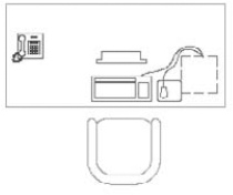
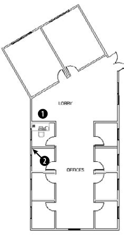
As you can see, copying to the Clipboard is ideal when you want to insert part of an existing drawing into another drawing. Drag-and-drop is also a simple way to insert one or more objects or an entire drawing.
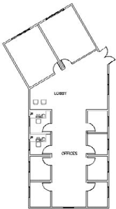
Your drawings do not exist in a vacuum. The objects in your drawing represent real objects. These objects have characteristics that you cannot visually represent in a drawing, such as cost, manufacturer, date purchased, and so on. Attributes are labels that are attached to blocks. Using attributes, you can attach labels with pertinent data to blocks. You can then extract the data and import it into a database program or spreadsheet, or even redisplay the data in an AutoCAD table.
Note
You can access and link to outside databases from within AutoCAD. See Chapter 20 for more information on external databases. You can also access data from objects that are not blocks; for more information, see the section on tables in Chapter 13. Both of these features are available in AutoCAD only.
You can also use attributes to place text relative to blocks. A common example is to use attributes for completing titleblock information, such as the drawing name, drawing number, date, scale, revision number, drafter, and so on. In this case, your plan is not to extract the data at all; you just use the attributes to help you precisely place the text in the titleblock. By inserting fields into these attributes, you can gain another benefit from attributes: automating the creation of titleblock text. For more information, see the discussion of fields in Chapter 13.
Attributes have several limitations. For example, they can only be attached to blocks (either regular or dynamic). However, you can create a dummy block that contains only attributes. The database features are also limited. Nevertheless, attributes are quite useful for simple database needs, as well as for placing text.
Defining an attribute creates a template into which you can place values when you insert the block. You define a tag that is equivalent to a field or category in a database. When you insert the block, you're prompted for the tag's value. For example, if your tag is COST, the value may be 865.79. This template is called an attribute definition.
The first procedure when working with attributes is to draw the individual objects that are to make up the block. If the block already exists, explode it, add the attributes, and then redefine the block.
The exception is when you want to create attributes without creating any other objects in the block. You might do this to extract attributes that apply to the drawing as a whole.
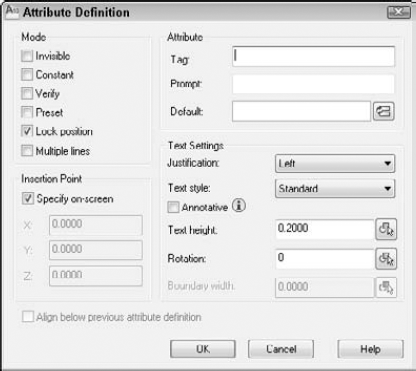
The Mode section of the dialog box sets certain attribute properties, including visibility and default value. These properties are shown in Table 18.5.
Table 18.5. Attribute Modes
Tip
Although by default, you see the simplified multiline text editor, you can use the full In-Place Text Editor to format multiple line attributes. Set the ATTIPE system variable to 1. However, if you need compatibility with earlier releases of AutoCAD or AutoCAD LT, you may need to return this system variable to its default value of 0. Otherwise, earlier releases may not display the attributes properly.
In the Attribute section of the dialog box, specify the tag, which is the name of the attribute. You use this tag when you extract the attributes. A tag is equivalent to a field in a database. For example, if you import the data into a spreadsheet, the tags would be the column heads. The tag name cannot include spaces or exclamation points (!), and it is converted to uppercase letters.
The prompt is simply a plain-English version of the tag. The prompt asks you for the value of the attribute. For example, if the tag is PUR_DATE, you could define the prompt as Date Purchased.
The default is used for setting a default value. You can use this if the value is usually the same. To insert a field, click the Insert Field button and choose a field from the Field dialog box, as I explain in Chapter 13. When you insert the block and are prompted for a value, you can either use the field value or you can change it.
If you checked the Multiple Lines check box, the Default text box is not available; instead, click the Ellipsis button that appears, and enter the default value in the simplified multiline text editor.
Tip
You can use the value to clarify a format that should be followed when entering information. For example, you could set the value of a date to dd/mm/yy so that users know how to format the date.
Use the Text Settings section to format the text. Choose a justification and text style from the drop-down list boxes. When you set the height, be sure to take into account the scale factor if you're not using annotative attributes. You can also set a rotation angle for the text.
Check the Annotative check box to make the attribute annotative so that it will automatically scale to match the scale of the viewport. For more information on annotative objects, see Chapter 17. I discuss annotative text, which is similar, in Chapter 13.
If you checked the Multiple Lines check box, the Boundary Width text box is available so that you can specify the width of the text. However, you can also adjust the width by dragging the arrows on the ruler of the simplified multiline text editor.
In the Insertion Point section, check the Specify On-Screen check box to specify the insertion point in your drawing. Uncheck the same check box if you want to prespecify coordinates. If you're using the attributes to place text in a schedule or titleblock, then the placement is obviously very important. If you're inserting invisible attributes, simply place them near the block. If you're creating more than one attribute for a block, place the attribute so that there is room for the other attributes underneath. When you've completed the dialog box, click OK. If you chose to specify the insertion point in the drawing, specify the point to insert the attribute.
Warning
If you're creating an attribute for a table or an electrical symbol, for example, you don't want the insertion point to be 0,0. Instead, you want an insertion point near the block. If you uncheck the Specify On-Screen check box and click OK to close the dialog box, the default insertion point is at 0,0. If 0,0 isn't visible on the screen, then you don't see the attribute — it seems to disappear! You can choose Undo from the Quick Access toolbar and create a new attribute in the right location, or move the attribute as explained in the section on editing attributes later in this chapter.
After you define one attribute, the Align Below Previous Attribute Definition check box is active. Select this option to line up succeeding attributes under the first one.
Now is the time to confirm that the attribute definitions are the way you want them. You can edit attribute definitions before they've been placed into a block in two ways:
Open the Properties palette (press Ctrl+1), select one attribute definition, and edit all its properties, such as the tag, value, prompt, and modes. You can also change properties such as the layer, text style, and so on.
Double-click the attribute text to start the DDEDIT command and change the tag, the prompt, and the default in the Edit Attribute Definition dialog box.
After you create the objects and their attribute definitions, you generally create a block. Choose Home tab
Tip
If the order of the attribute prompts is important, don't use a window to select the attributes. Select them in the order in which you want the prompts to appear. You can then use a crossing or window box to select the rest of the objects to be included in the block. The order of the attribute prompts will be important if you're taking the data for the attributes from a listing, such as a spreadsheet that you've printed out.
Name the block and define the block's insertion point as you would normally. Generally, you want to check Delete because you don't need the block without the attribute tags in your drawing. Remember that you can make the block annotative, if you want.
Don't forget to pay attention to the layer of the attributes, just as you would the layer of the block objects. The same layer rules apply to attributes as to blocks.
Note
If you want to insert the objects and the attributes as a file rather than as a block, you don't need to create a block at all. Create a drawing that contains just the objects and its attributes. Use the BASE command to change the base point of the drawing (usually 0,0) to the desired insertion point of the block. Then save the drawing. When you insert the drawing, you are prompted for the attributes, as usual. Use this technique for blocks and attributes that you use for more than one drawing, such as a titleblock.
After you create the block, you cannot edit the attributes in the Properties palette. I cover other techniques for editing attributes later in this chapter.
Note
The drawing that you need for the following exercise on creating attributes, ab18-i.dwg, is in the Drawings folder on the DVD.
STEPS: Creating Attributes
Open
ab18-i.dwgfrom the DVD. This is a plan of an office building zoomed in to one office. A file containing one set of office furniture has been inserted, as shown in Figure 18.33.Save the drawing as
ab18-09.dwgin yourAutoCAD Biblefolder.Choose Home tab

In the Attribute section, enter the following:
Tag:
mfrPrompt:ManufacturerDefault: American Office FurnitureLeave the Text Settings as they are. Make sure that the Specify On-Screen check box is checked and click OK. Pick point
Repeat the ATTDEF command. Check the Align Below Previous Attribute Definition check box. Enter the following:
Tag:
pur_datePrompt:Date purchasedDefault:3/91Click OK.
Choose Home tab
A message asks whether you want to redefine the block because there is already a block definition with the same name in the drawing. Choose Redefine Block.
Save your drawing. If you're continuing on to the next exercise, leave the drawing open.
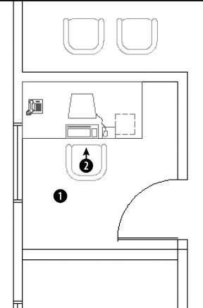
Note
Redefining a block updates only block geometry, not attributes. Therefore, if you add attribute definitions to a block, only new blocks that you'll insert include the attributes. Existing blocks don't gain these new attribute definitions. To update existing blocks with their current attribute definitions, use the ATTSYNC command.
Note
AutoCAD LT now supports the ability to synchronize existing blocks with their current attribute definitions.
After you define a block with attributes, you insert it as you would any block. AutoCAD automatically detects the existence of the attributes and prompts you for their values. After you enter the values, the block and its attributes appear in the drawing.
Note
You can insert attributes either in a dialog box or on the command line. By default, you insert them on the command line. To use a dialog box, set the ATTDIA system variable to 1. You would use the command line to automate the insertion of attributes by using an AutoLISP routine, menu item, or script file. When you use a dialog box, the Verify and Constant modes are not used. To skip all the prompts and automatically use default values that you have set, set the ATTREQ system variable to 0.
Note
The drawing that you need for the following exercise on inserting blocks with attributes, ab18-08.dwg, is in your AutoCAD Bible folder if you did the previous exercise. Otherwise, you can find it in the Results folder on the DVD.
STEPS: Inserting Blocks with Attributes
Use
ab18-09.dwgif you have it open from the previous exercise. Otherwise, open it from theResultsfolder of the DVD.Save the drawing as
ab18-10.dwgin yourAutoCAD Biblefolder.Type attdia
Choose Home tab
Pick a point in front of the desk (turn off Object Snap if necessary) to insert the armchair and open the Edit Attributes dialog box. The values that were entered when the attributes were defined are displayed, but you can change them.
The default values exist because most of the furniture was purchased at one time when the office was opened. However, let's assume that this chair was purchased later. Change the purchase date to 3/05. Click OK. Because the attributes are invisible, you see only the chair, but the values do exist in the drawing database.
Save the drawing.
After you create the block, you can use the Block Attribute Manager. The Block Attribute Manager manages all properties of block attributes in one place. Use the Block Attribute Manager and its Edit Attribute dialog box to edit any aspect of block attributes.
Note
AutoCAD LT now supports the Block Attribute Manager.
After you insert a block and give values to its attributes, you can modify the following:
After you make your changes, you can update all the blocks in your drawing to reflect the changes.
Choose Home tab
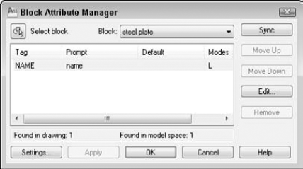
From the Block drop-down list in the Block Attribute Manager, choose the block whose attribute values you want to change. You can also click Select Block to select the block in your drawing. Use the Block Attribute Manager to:
Change the order of the attribute prompts when you insert a block with attributes. Choose any attribute from the list in the Block Attribute Manager, and click Move Down or Move Up. Continue to use this procedure until you have the order that you want.
Delete an attribute. Choose it and click Remove.
Change which attribute properties are listed in the Block Attribute Manager. Click Settings. In the Block Attribute Settings dialog box, click all the properties that you want to see listed. For example, you can include columns for layer, style (text style), and color. Click OK.
Tip
When you add properties to the listing in the Block Attribute Manager, resize the dialog box so that you can see all the columns.
Edit the attributes, including prompt, default, text display, and properties. Click Edit to open the Edit Attribute dialog box, as shown in Figure 18.35.
Update all the blocks in your drawing to reflect the changes that you've made. Click Sync. Usually you do this after using the Edit Attribute dialog box. Because changes such as attribute order and mode affect only new insertions of the block, this update brings existing blocks into concordance with new blocks.
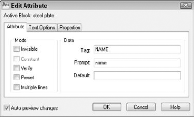
Use the Edit Attribute dialog box to edit all the properties of individual attributes. This dialog box has three tabs:
Attribute. Allows you to change the mode and attribute properties. For example, in the Mode section, you can change the visibility of attributes. In the Data section, you can change the tag, prompt, and default. You can right-click the Default text box and choose Insert Field to use a field. (See Chapter 13 for a discussion of fields.)
Text Options. Allows you to change text style, height, justification, and so on.
Properties. Allows you to change attribute layer, color, linetype, and so on.
After you finish making changes, click OK in the Edit Attribute dialog box to return to the Block Attribute Manager. Click OK again to return to your drawing.
Note
Insrot is a program that inserts a block at a specified rotation but keeps the attributes horizontal. Look in SoftwareChapter 18Insrot. Attstrip removes all attributes from selected blocks. Look in SoftwareChapter 18attstrip.
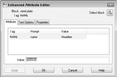
As you can see, the Enhanced Attribute Editor is similar to the Edit Attribute dialog box. For example, it has the same three tabs. However, the Attribute tab enables you to change attribute values, something that you can't do in the Edit Attribute dialog box. To change an attribute's value, select it and type a new value in the Value text box. You can right-click the Value text box and choose Insert Field to use a field. (See Chapter 13 for more about fields.) The Text Options and Properties tabs of the Enhanced Attribute Editor are the same as in the Edit Attribute dialog box.
Warning
If you explode a block with attributes, you lose the attribute values.
In both AutoCAD and AutoCAD LT, you can change attribute values by using the ATTEDIT command to open the Edit Attributes dialog box, as shown in Figure 18.37.
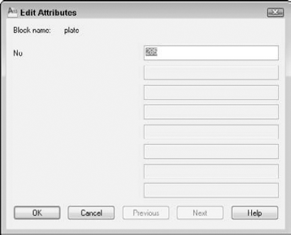
If a block has a number of attributes and you want to change them all in order, this dialog box makes it easy to go through all the attributes quickly. Press Tab to go to the next attribute.
One way to change attribute properties is to explode the block and double-click the attribute. This starts the DDEDIT command and opens the Edit Attribute Definition dialog box, where you can change the tag, prompt, and default value. You can then redefine the block. The preferred method though is to use the Block Attribute Manager, as explained in the previous section.
When you create invisible attributes, you can't edit them because you can't select them. The ATTDISP command controls attribute visibility globally, for all attributes in your drawing. Choose Home tab
Retain Display. Attributes that were created as visible are visible. Attributes that were created as invisible are invisible. This is the default option.
Display All. All attributes are visible.
Hide All. All attributes are invisible.
Changing the current option causes your drawing to regenerate.
In both AutoCAD and AutoCAD LT, you can also use the -ATTEDIT command on the command line to make global changes. If you answer No to the Edit attributes one at a time? [Yes/No] <Y>: prompt, you can make global changes to attribute values. For example, you can change all instances of A- in your part numbers to B-. You can even change invisible attribute values.
To use -ATTEDIT to make global changes, follow these steps:
Choose Home tab
At the
Edit attributes one at a time? [Yes/No] <Y>:prompt, type nAt the
Edit only attributes visible on screen? [Yes/No] <Y>:prompt, answer y or nAt the
Enter block name specification <*>:prompt, you can type a block name to limit the changes to one block, or press Enter to include any block.At the
Enter attribute tag specification <*>:prompt, you can type a tag to limit the changes to one tag type, or press Enter to include any tag.At the
Enter attribute value specification <*>:prompt, you can type a value to limit the changes to one value, or press Enter to include any value.If you chose to edit only attributes that are visible on-screen, you see the
Select Attributes:prompt. (If not, skip to Step 8.) Pick each attribute that you want to modify, or use a window. Press Enter to end selection. If you include other objects or blocks that do not fit the block name, attribute tag, or attribute value specifications that you made, then these other objects are not selected. The command line informs you of how many attributes were selected.At the
Enter string to change:prompt, type the text string (any consecutive text) that you want to change.At the
Enter new string:prompt, type the text string that will replace the old string.
If you chose to edit attributes that are not visible on the screen, the drawing regenerates, and the command line lists the changes that it made.
You can redefine a block with attributes to include different objects and attributes, using the ATTREDEF command. Redefining a block lets you add or delete attributes or redefine a block that contains attributes. Follow these steps:
Note
AutoCAD LT does not include this feature. Instead, explode the block and start from scratch. You can use the DDEDIT command to change attributes after you explode a block.
Explode one of the blocks with attributes. If there are nested blocks that you want to change, explode them, too.
If you want to add attributes, define and place them. Delete unwanted attributes. Make any other changes that you want to the objects.
Type attredef
At the
Enter name of block you wish to redefine:prompt, type the name of the block.At the
Select objects for new Block...:prompt, select the objects and the attributes that you want to include. Do not include any existing attributes that you want to delete.At the
Specify insertion base point of new Block:prompt, pick the base point for the block.
Here's how your drawing handles the changes:
If you created new attributes, the command places them for all existing blocks and gives them their default values.
Any attributes that you did not change retain their old values for all existing blocks.
Any attributes that you did not include in the new block definition are deleted from existing blocks.
Note
The drawing that you need for the following exercise on editing attributes, ab18-j.dwg, is in the Drawings folder on the DVD.
STEPS: Editing Attributes
Open
ab18-j.dwgfrom the DVD.Save the file as
ab18-11.dwgin yourAutoCAD Biblefolder. This is a portion of an office building plan layout, as shown in Figure 18.38.
Notice that the manufacturer is American Office Furniture. Because these attributes are invisible, you can't see the result in the drawing. Click OK.
To see the attributes, choose Home tab

Edit attributes one at a time? [Yes/No] <Y>:
nPerforming global editing of attribute values. Edit only attributes visible on screen? [Yes/No] <Y>:nDrawing must be regenerated afterwards. Enter block name specification <*>:armchairEnter attribute tag specification <*>:Enter attribute value specification <*>:
6 attributes selected. Enter string to change:AmericanEnter new string:Acme(Press F2 to hide the text window if it is open.)
To redefine the block, do one of the following:
If you have AutoCAD: Type attredef
Enter name of Block you wish to redefine:
armchairSelect objects for new Block...Select objects:Use a window to select the chair and the three attributes. Press Enter to end selection. Specify insertion base point of new Block: Use an Endpoint object snap to pick the endpoint at.If you have AutoCAD LT: Choose Home tab
The armchair block disappears.
Choose Insert in the Block panel. In the Insert dialog box, choose armchair from the Name drop-down list. With Specify On-screen checked only for Insertion Point, click OK. Insert the chair at
AutoCAD only: To verify that your drawing has redefined the block elsewhere, choose Home tab
Zoom in closely to the telephone at
Choose Home tab
The phone number is now blue (or cyan).
Choose View tab
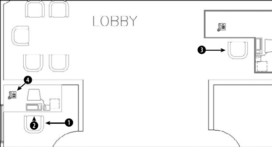
Note
The Express Tools command BURST (choose Express Tools tab
Note
The Data Extraction Wizard exists only in AutoCAD. For AutoCAD LT, you need to use the method that I explain in the sidebar, "Creating a template file the old-fashioned way."
On the Begin screen of the wizard, choose one of two options:
Create a new data extraction. You can start from scratch or use a DXE or BLK file, which are templates that you create in the Data Extraction Wizard of AutoCAD 2010 or previous releases. These extraction template files save the parameters of the data extraction, so that you don't have to create them all over again.
Edit an existing data extraction. Choose this option if you previously extracted data and want to modify the results.
Note
Don't confuse the template file used for extracting attributes with the template file (with a filename extension of DWT that you use as a basis for opening a drawing. Keep in mind that you can't use ASCII template files with the Data Extraction Wizard; you can only use .dxe or .blk templates.
In either case, click Next. The following instructions assume that you chose the first option.
AutoCAD saves the extraction parameters as a DXE file, and so the Save Data Extraction As dialog box opens, where you choose a location and name for the file.
Click Settings to specify some block and block-count settings:
Extract Objects from Blocks. Includes nested blocks.
Extract Objects from Xrefs. Includes objects in external references (xrefs). See Chapter 19 for coverage of xrefs.
Include Xrefs in Block Counts. When counting blocks, counts xrefs as blocks.
In the Extract From section, you can include all objects or only objects in model space. Then click OK. Click Next to go to the next screen, Select Objects, as shown in Figure 18.39. Here you choose the objects with which you want to work. If you selected objects in the previous screen, you may have what you want here, but you may still find objects that you don't want to include.
Note
You can extract data from any object in your drawing, but attributes apply only to blocks.
If you're only interested in blocks and attributes that you've created, uncheck the Display All Object Types check box and choose the Display Blocks Only option. By checking the Display Blocks with Attributes Only check box, you can remove other blocks from your drawing. Check the Display Objects Currently In-Use Only check box to remove objects such as blocks that are defined but not inserted into the drawing, or objects from other drawings that you don't want to include. Uncheck this check box if you need to extract objects across multiple drawings and need access to certain objects not in the current drawing.
When you're done, you should see listed only the types of objects that you need. Then individually check or uncheck the objects listed. For example, you may want to extract attributes from some blocks, but not from others. Then click Next.
On the Select Properties screen, shown in Figure 18.40, you choose which properties you want to extract. If you want to extract only attributes, uncheck all the other check boxes in the Category Filter section. (I discuss the other categories more in Chapter 13.) You should be left with just the attributes that you want to extract. Click Next.
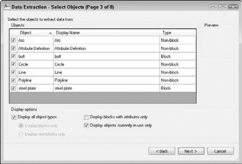
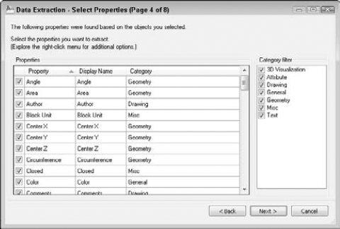
On the Refine Data screen, shown in Figure 18.41, you have three check boxes which allow you to combine (or not combine) identical rows, show (or not show) a column that counts the blocks, and show (or not show) a column that lists the name of the block. You can sort each column by clicking the column's heading. Finally, you can add a link to external data by clicking the Link External Data button. I cover this feature in Chapter 13.
You can click Full Preview to preview the resulting data. Click the window's Close button to return to the wizard. Then click Next.
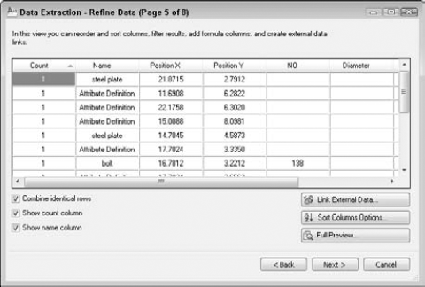
On the Choose Output screen, check the output that you want to create. You can output to an AutoCAD table, an external file, or both. You can create the following types of files:
CSV (Comma Delimited) (
*.csv). Lists its attribute values with a comma between each value. Most spreadsheets and databases can import this format.Tab Delimited File (
*.txt). This is like a CSV file, except that there is a tab between each attribute value.Microsoft Access Database (
*.mdb). Creates a Microsoft Office Access database file.
If you check the Output Data to External File check box, enter the filename in the text box, or click the Ellipsis button to open the Save As dialog box, where you can browse to the desired location, name the file, and choose the file type. You choose the file type by specifying the filename extension. Click Save. To continue, click Next.
If you chose to export to a table, on the next screen you can choose a table title and style. If you don't have a table style (except the default, Standard), click the Table Style button to open the Table Style dialog box. Click New to create a new table style. When you have chosen a table title and style, click Next.
The Finish screen just tells you that you'll need to specify an insertion point if you chose to create a table and that your file will be saved if you chose to create an external file. Then click Finish.
If you chose to create a table, you see the table at the cursor, and you see the Specify insertion point: prompt. Specify a location to place the table. If you chose to create an external file, you see a message on the command line providing the name of the file.
Note
If you have AutoCAD LT, skip this exercise, and use the following exercise instead.
Note
The drawing that you need for the following exercise on extracting attribute data in AutoCAD, ab18-k.dwg, is in the Drawings folder on the DVD.
STEPS: Extracting Attribute Data in AutoCAD
Open
ab18-k.dwgfrom the DVD. This is the same office building plan used earlier in this chapter, as shown in Figure 18.42. Save the drawing asab18-12.dwgin yourAutoCAD Biblefolder. Change the current layer to 0.
The Create a New Data Extraction option should be selected on the Begin screen. Click Next.
The Save Data Extraction As dialog box opens. Navigate to your
AutoCAD Biblefolder. In the File Name text box, enter ab18-12.dxe and click Save.On the Define Data Source screen, the Drawings/Sheet Set option should be selected. The Include Current Drawing check box should also be checked. Click Next.
On the Select Objects screen, uncheck the Display All Object Types check box and check the Display Blocks Only option. Check the Display Blocks with Attributes Only check box. You should now see three objects listed, ARMCHAIR, DESK, and PHONE. Uncheck DESK and PHONE to extract the data for the armchair blocks only. Click Next.
On the Select Properties screen, uncheck Drawing and General in the Category Filter pane. In the Properties pane, click the Category column to sort by category. Leave only the following properties checked:
For the Attributes category. COLOR, MFR, and PUR_DATE
For the Geometry category. Position X and Position Y
For the Misc category. Rotation
You can change the display name of the properties. Click in the appropriate row of the Display Name column twice to select the display name and make the following changes:
Click Next. (If you get a message about nonuniformly scaled blocks, click OK.)
On the Refine Data screen, you should see the data with each attribute in its own column. You can resize the window to see all the data. Click the Manufacturer column to sort the list by manufacturer. Note how the column names match the changes you made to the display names. Click Next.
In the Output Options section, check both check boxes to create both a table and an external file. Click the Ellipsis button next to the External File text box. In the Save As dialog box, navigate to your
AutoCAD Biblefolder. From the Files of Type drop-down list, choose*.csv. Leave the default name (ab18-12.csv) and click Save. (If you have Microsoft Excel or Access, you can choose the appropriate file type for one of those applications.) Click Next.On the Table Style screen, type Armchair Data in the Enter a Title for Your Table text box. The table style should be set to Office. Click Next.
On the Finish screen, click Finish.
On the command line, you see a message that the CSV file was successfully created. You also see a
Specify insertion point:prompt for the table. Pick a point to the right of the floor plan to insert the table.To view the CSV file, open Windows Explorer and double-click
ab18-12.csvin yourAutoCAD Biblefolder. It should open in Microsoft Excel or another application that opens CSV files on your system. The data should look like Figure 18.43.Save your drawing.
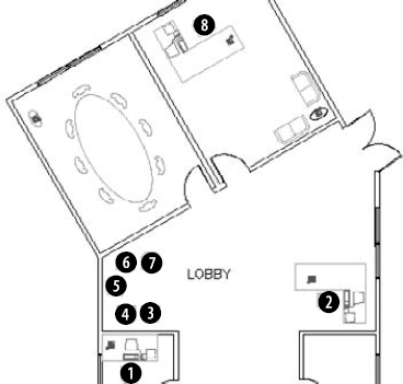
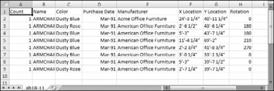
Note
If you export attributes in tab-delimited (.txt) format, you can open the Multiline Text Editor and click Import Text to import the output file into your drawing. You can also open the output file, copy it to the Clipboard, and paste it into your drawing. The Import Text method enables you to format the text as you would any multiline text, but may take some experimenting to align the columns. You cannot format the text that you import by using the Clipboard method, but it's nicely lined up in columns. Using the table option as you did in the exercise provides the best combination of formatting options.
Note
The files that you need for the following exercise on extracting attribute data in AutoCAD LT, ab18-k.dwg and ab18-k.txt, are in the Drawings folder on the DVD.
STEPS: Extracting Attribute Data in AutoCAD LT
Open
ab18-k.dwgfrom the DVD. This is the same office building plan used earlier in this chapter, as shown in Figure 18.42.Type attext
Choose the Space Delimited File (SDF) option.
Choose Select Objects. Pick the five armchairs in the lobby and the three offices. Press Enter to end selection.
Choose Template File. In the Template File dialog box, navigate to and choose
ab18-k.txtfrom the DVD. Click Open.Choose Output File. In the Output File dialog box, choose your
AutoCAD Biblefolder and name the file ab18-12.txt. Click Save.Click OK. The command line displays the message
8 records in extract file.To view the output file, choose Start
This exercise shows how to extract attributes using space-delimited format. This format is easier to import into AutoCAD by copying and pasting. However, comma-delimited format is easier to import into most spreadsheet programs.
In this chapter, I covered all the ways that you can use blocks and attributes in your drawings. You read about:
Combining objects into blocks in your drawings so that you can edit them as a unit
Inserting blocks at any scale and rotation
Saving a block as a file
Inserting blocks with the INSERT command
Using the DesignCenter to import blocks from other drawings
Creating dynamic blocks with action-based parameters and parametric constraints
Using dynamic blocks
Copying objects by using the Windows Clipboard and drag-and-drop
Using attributes to place text and to create simple databases
Defining attributes
Inserting blocks with attributes and assigning values to the attributes
Extracting attribute data in both AutoCAD and AutoCAD LT
In the next chapter, I explain how to insert references (xrefs) to other files in your drawings.