
AutoCAD and AutoCAD LT offer many ways to integrate your drawings with the Internet. You can open drawings from a Web site, hyperlink objects to anywhere on the Web, and publish drawings in PNG, JPG, DWF, or DWFx format on a Web site. When you access a Web site (perhaps your company's intranet), you can find blocks or other data, and drag them into your drawing. This chapter covers all the ways to connect your drawings with the Internet.
You can share your 3D drawings in the 3D DWF or 3D DWFx format. The DWF and DWFx formats are not only for use on the Internet; your colleagues can also view your DWF and DWFx files by using Autodesk Design Review.
You can instantly send your drawings to others on your team or to your clients, by either faxing or e-mailing them, just as you fax and e-mail other documents. You can fax a drawing if the recipient doesn't have AutoCAD or AutoCAD LT and wants to quickly see the drawing on paper. (Later in this chapter, I explain how someone can use Autodesk Design Review to view AutoCAD or AutoCAD LT drawings.)
You can also send a drawing to an FTP site. Another option is to create a PDF file from the drawing and then e-mail the PDF file. Use e-mail if the recipient has AutoCAD or AutoCAD LT; however, you may need to edit the drawing. I explain how to create a PDF file from a drawing in Chapter 27.
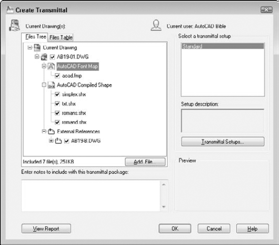
Figure 28.1. The Create Transmittal dialog box enables you to create a transmittal file that you can attach to an e-mail message. The transmittal file contains a drawing, along with its associated files.
You can write a note to the recipient in the Notes section. The content of the Notes section becomes part of the transmittal report, a separate file that is included in the EXE or ZIP file. If you send an e-mail message, the note becomes the body of the message.
If you have a saved transmittal setting, choose it from the Select a Transmittal Setup box and click OK. Otherwise, click Transmittal Setups to open the Transmittal Setups dialog box. To create a new setup, click New, name the setup, and click Continue. To modify an existing setup, select the setup and click Modify. In both cases, you end up in the Modify Transmittal Setup dialog box, as shown in Figure 28.2.
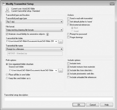
Figure 28.2. Use the Modify Transmittal Setup dialog box to specify how to structure your transmittal.
From the Transmittal Package Type drop-down list, choose one of the following types of transmittals:
Folder (set of files). Creates a folder that includes all the files in the transmittal. The files are not compressed.
Self-extracting executable (
*.exe). Creates a compressed EXE file. Recipients can double-click the file to decompress and extract the files.Warning
Some people won't open EXE or ZIP files for fear of computer viruses, so you might need to notify your recipient in advance that you're sending an EXE or ZIP file. Also, some e-mail programs block EXE and ZIP attachments. You might also consider using a secure FTP site or a project collaboration Web portal like Autodesk Buzzsaw to work around these limitations.
Zip (
*.zip). Creates a compressed ZIP file.
From the File Format drop-down list, you can choose to save files in earlier release formats if you want. From the Transmittal File Folder drop-down list, choose a location to save the transmittal files, or click Browse to specify another location. You can leave this item blank to save the files in the same folder as the first drawing on the list in the Create Transmittal dialog box. If you're transmitting a sheet set (AutoCAD only), the transmittal file goes in the same folder as the drawing set data (DST) file.
For drawings with annotative objects, you can check or uncheck the Maintain Visual Fidelity for Annotative Objects check box. This sets the SAVEFIDELITY system variable, which determines what happens when someone views the drawing in earlier releases. By default, this system variable is on (the check box is checked), which saves each scale representation as a separate block on a separate layer. This allows users in previous versions to choose which version they want by turning off layers or deleting blocks. If you work in model space and don't need layouts to look the same as in 2010, you should uncheck this check box to avoid creating all the additional layers and blocks when saving to the AutoCAD 2007 or earlier file format.
If you create an EXE or ZIP file, you can use the Transmittal File Name drop-down list to choose how you want to name the file. You can choose to be prompted for a filename, have eTransmit assign a name and overwrite any existing file with that name, or have eTransmit assign a name and increment the filename (add a number) to avoid overwriting an existing file.
Tip
Because you often don't need the transmittal file after you've sent it (you already have all the files), you can put it in the WindowsTemp file or another location where you place files that you'll delete.
Choose one of the following Path options:
The Use Organized Folder Structure option creates a hierarchical folder structure based on the structure of the files in the transmittal package. You can specify the root folder for this structure. When the recipient opens the transmittal package, all these folders are created.
The Place All Files in One Folder option puts all the files in one folder that the recipient specifies.
The Keep Files and Folders As Is option retains the exact paths of the existing files and folders.
Use the following Actions options to define which actions to use when creating the transmittal package:
The Send E-mail with Transmittal check box opens your e-mail program and creates a new message with the files and notes as attachments and as the body of the message, respectively. Using this feature makes sending your drawings very easy.
The Set Default Plotter to 'None' check box removes the plotter information from the drawings, because it's probably not useful to your recipient.
The Bind External References check box binds xrefs to their host drawings.
The Prompt for Password check box opens a dialog box (after you save the transmittal file) where you can specify a password. Be sure to tell your recipient the password.
The Purge Drawings check box removes all unused named objects in the drawing before adding a drawing to the transmittal package. Named objects include layers, blocks, text styles, and so on.
Use the following Include options to define which types of files to include when creating the transmittal package:
The Include Fonts check box includes the AutoCAD fonts in the transmittal. If your drawing only uses fonts included in a normal installation of AutoCAD or AutoCAD LT, you can probably assume that your recipients have them. You can include TrueType fonts, but make sure that you can redistribute them as they are often licensed and proprietary.
The Include Textures from Materials check box includes texture files that you have used as the basis for materials. Materials are used in rendering. (See Chapter 25 for more information on rendering.)
The Include Files from Data Links check box includes Excel or CSV files that you have linked to in the drawing. (See Chapter 13 for a discussion of data links.)
The Include Photometric Web Files check box includes Web files that contain photometric data. (See Chapter 25 for more information.)
The Include Unloaded Reference Files check box includes unloaded xrefs, images, and underlays. (See Chapter 19 for more information.)
Note
The Include Unloaded Reference Files option is new for AutoCAD 2010 and AutoCAD LT 2010. This feature allows you to remove unloaded xrefs, images, and underlays from the drawings before sending them to others. At the bottom of the dialog box, you can add a description for the transmittal. Then click OK. The Transmittal Setups dialog box reappears, where you can choose the transmittal setup that you want. Then click Close.
You're now back in the Create Transmittal dialog box. Click the Files Table tab to see the files that will be included in your transmittal. The normal files are acad.fmp or acadlt.fmp (the font map that specifies font substitutions), SHX files (usually compiled fonts), TTF files (TrueType fonts), and any xrefs, raster images, or standards files that are attached to the drawing.
Warning
The eTransmit feature does not include files referred to by hyperlinks. Therefore, if you want hyperlinks to work, you need to add the referenced files.
To add files, click Add File, navigate to the desired file, select it, and click Open. To see the Transmittal Report, click the View Report button. The report includes your notes and instructions to the recipient for using the associated files. For example, there are instructions for where to place SHX files and xrefs. Choose Save As to create an additional copy of the report for your own records.
When you're done, click OK. If you checked Send E-mail with Transmittal, your e-mail program opens, and you can send an e-mail message and the files. Either way, eTransmit creates the type of transmittal files that you requested.
You can access drawings, blocks, and so on from the Internet in the same way that you currently access them on your hard drive or network. Sharing drawings around the world can be as easy as opening a drawing on your hard drive. You have two methods for bringing objects from the Internet into your drawings.
If you drag with the right mouse button, a prompt asks you whether you want to save associated blocks or data when you drag with the right mouse button. Also, inserted blocks automatically include a hyperlink to the source of the content.
You can hyperlink objects in your drawing to files or Web sites that may be located anywhere on the Internet, a network, or your own hard drive. A hyperlink creates a permanent connection between your drawing and other files that may provide supporting documentation or additional information.
When you follow a hyperlink, the appropriate application is opened with the specified file. For example, a Web site is opened in your Web browser, or a word-processing document is opened in your word-processing application.
Before you create your hyperlink, consider the environment in which it will be used. The file or Web page that you're linking to must be available for the hyperlink to work. For example, if you send a drawing with hyperlinks to a colleague, be sure to include the files to which the hyperlinks refer. If you're posting the drawing on a Web site as a DWF or DWFx file, you need to upload the files that the hyperlinks refer to, along with the DWF or DWFx file.
Here's how you create a hyperlink:
Select one or more objects in your drawing. The hyperlink will be attached to these objects.
Choose Insert tab

Use the Link To list to choose the type of hyperlink that you want to create. The central portion of the dialog box changes, depending on which of these options you choose: a Web page, named view, or e-mail address.
Existing File or Web Page. Creates a hyperlink to another file (on your own computer, network, intranet, or the Internet) or a Web page. You can choose from Recent Files, Browsed Pages, or Inserted Links.
View of This Drawing. Creates a hyperlink to a named view, camera, or layout in the open drawing. (I explain cameras in Chapter 22. A camera is a type of 3D named view.) You can use this option to help viewers navigate to detail views or schedules (tables of data) in the drawing.
E-mail Address. Opens the viewer's e-mail program and starts a new message to the specified address.
To help you specify the file or Web page, click either the File button or the Web Page button at the right side of the dialog box. To specify a named view in a drawing, click the Target button. In the Select Place in Document dialog box, click the plus sign next to the layout and select a view. Click OK.
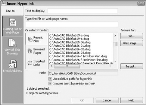
In the Text to Display text box, type a short description of the hyperlink. The description is displayed as the tooltip. If you don't create a description, when you pass the cursor over the hyperlink, the tooltip lists the URL or filename. If the URL or filename is confusing, use a description instead.
Uncheck the Use Relative Path for Hyperlink check box if you want to use the entire path that you placed in the Type of File or Web Page Name text box. A relative path uses a base as a given, and requires you to specify only the part of the path after the base. Use relative paths when the hyperlinked file is in the same folder as the drawing.
Uncheck the Convert DWG Hyperlinks to DWF check box if you don't want to convert drawing hyperlinks to DWF or DWFx hyperlinks. For example, if this box is checked, a hyperlink to mydrawing.dwg becomes a hyperlink to mydrawing.dwf. If you plan to create a DWF or DWFx file from the drawing that you're hyperlinking to, leave this check box checked.
Click OK to create the hyperlink.
Check the hyperlink by passing the cursor over the object to which you attached the hyperlink. You see the Web cursor, as shown in Figure 28.5.
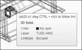
After you create a hyperlink, you can use it at any time to open the associated file or to move to the associated location within the drawing. To open a file associated with a hyperlink, Ctrl+click any hyperlinked object. Remember that you can't just click a hyperlink as you do on a Web site, because that just selects the object in your drawing. Make sure that the hyperlink icon appears before you click, because pressing Ctrl and clicking is also a way to select edges and faces of 3D solids.
To edit any feature of a hyperlink, select the hyperlinked object and choose Insert tab
Note
The files used in the following exercise on creating hyperlinks, ab28-a.dwg, ab28-a1.dwg, and ab28-a2.dwg, are in the Drawings folder on the DVD.
STEPS: Creating Hyperlinks
Open
ab28-a.dwgfrom the DVD.Save the file as
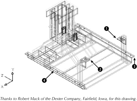
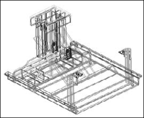
ab28-01.dwgin yourAutoCAD Biblefolder. This is a 3D drawing of a base assembly frame for an industrial washer, as shown in Figure 28.6.Copy
ab28-a1.dwgandab28-a2.dwgfrom the DVD to yourAutoCAD Biblefolder. (You can use Windows Explorer to drag the files.)Choose Insert tab
Click File. Choose
ab28-a1.dwgin yourAutoCAD Biblefolder. Click Open. Click OK in the Insert Hyperlink dialog box.Repeat the HYPERLINK command. This time attach

Ctrl+click the hyperlink at

Save your drawing. Keep it open if you're going on to the next exercise.
Note
The Express Tools contain three commands to help you find and change URLs that you create with hyperlinks. SHOWURLS (choose Express Tools tab
You can save drawings as DWF (Design Web Format) or DWFx files. You can use DWF files as a way to deliver files to clients and colleagues. If you place a DWF drawing on a Web site, others can view the drawing in their browser. They can also zoom, pan, and print the drawing. You can place hyperlinks in your drawing so that viewers can jump to supporting data, to other DWF or DWFx drawings, or to other Web sites. Using Autodesk Design Review, others can view DWF or DWFx files on their computer; as a result, the DWF or DWFx format is not limited to use on a Web site.
The DWFx file format is based on Microsoft's XML Paper Specification (XPS), which allows anyone to view the 2D geometry of the file without the need for software other than the XPS Viewer. The XPS Viewer comes with Windows Vista, and you can install it on Windows XP. You can use Autodesk Design Review to view the 3D geometry of a DWFx file, view metadata, change the visibility of objects on a layer, and much more.
You can publish 2D DWF and DWFX, and 3D DWF and DWFx files in AutoCAD. (AutoCAD LT does not create 3D DWF or DWFx files.) 3D DWF and 3D DWFx files are similar to 2D DWF and DWFx files, but they have some limitations. The Autodesk Design Review can display 3D DWF and DWFx files and includes a 3D Orbit viewing option. I explain 3D DWF and DWFx files later in this chapter.
DWF and DWFx files are image formats for drawings. The DWF and DWFx formats allow for multiple pages. You can include as many drawings as you want, including the layouts you've created for each drawing; however, very large numbers of layouts may create a file that is too large to open and view.
The DWF and DWFx formats have several advantages:
They are a vector format. Viewers can zoom in closely and see the details clearly.
2D DWF and DWFx files are 2D representations, similar to a plot. The actual objects are not available to the viewer. They cannot edit the drawing, and you can restrict access to object information such as layers, object coordinates, and so on. This feature maintains security for the creator of the drawing.
3D DWF and DWFx files do not expose the actual objects. Viewers can view the model from any angle but cannot access object information.
DWF and DWFx files are compressed while being transmitted. Their small size reduces the time it takes to download and view them.
The Autodesk Design Review enables people without AutoCAD or AutoCAD LT to view your drawings. You can also post DWF and DWFx files on a Web site.
Viewers of 2D DWF and DWFx files can zoom to named views. Some drawing information is available. For both 2D and 3D DWF and DWFx files, you can choose to allow viewers to turn layers on and off, see block properties and attributes, and display sheet set information. You have full control over whether you want to enable this information.
2D DWF and DWFx files support hyperlinks to other drawings, data, or files. You can provide the viewer with supporting schedules, and so on. (3D DWF and DWFx files don't support hyperlinks.)
To create a 2D DWF or DWFx file from a set of drawings, you use the PUBLISH command to do the following:
Create the drawing set; that is, the list of drawings and layouts to include in the DWF or DWFx file.
Specify a page setup for each drawing.
Save the list of drawings or load an existing list.
The PUBLISH command creates the multipage DWF or DWFx format. The PUBLISHTOWEB command, which creates DWF and DWFx files (but can also create JPEG or PNG files), is different — it uses a wizard and a template to format a Web page containing images of your drawings. The PUBLISHTOWEB command is covered later in this chapter. Before using the PUBLISH command, save your drawing.
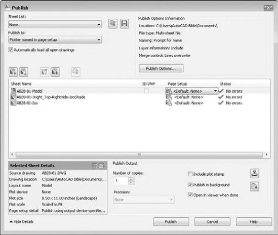
The next step is to add any other drawings and layouts that you want to include in the drawing list. The PUBLISH command streamlines the process of defining scale and plot area for each drawing by using the page setup information defined with the layouts. Because layouts include this information, you can quickly create drawing sets for many drawings without individually deciding how to plot each drawing. You can specify a saved page setup for individual drawings for more control. (For more information on page setups and layouts, see Chapter 17.)
Note
By default, the Publish dialog box initially lists all sheets, models, and layouts for all open drawings. To list only the sheets of the current drawing, uncheck the Automatically Load All Open Drawings check box in the Publish dialog box or change the value of the PUBLISHALLSHEETS system variable to 0.
You can add new drawings and layouts to the drawing list, using any of the following methods:
Drag drawings directly from Windows Explorer. You can add large numbers of drawings this way — in any folder, click the first drawing, press Shift, and click the last drawing.

Click Load Sheet List and choose a saved drawing list from the Load List of Sheets dialog box.
Tip
You can use the +PUBLISH command, a variant of the PUBLISH command that lets you start with a saved DSD file instead of with the current, or all open, drawings. The Select List of Sheets dialog box opens. Choose a DSD file and click Select. You can use the –PUBLISH command with a saved DSD file to publish DWF files from a script file. You then get a prompt for the DSD file. The process automatically generates a log file (with the name of the drawing list and an extension of .csv) that you can look at in case there are errors.
By default, the model tab and layouts tabs for each drawing are all included in the drawing list. If you don't want to see the model tab for drawings, right-click over the drawing list in the Publish dialog box and choose Include Model When Adding Sheets if it has a checkmark. Likewise, you can right-click the drawing list and choose Include Layouts When Adding Sheets. After you change this setting, new drawings that you add to the drawing set will not include the tab that you unchecked.
After you have the drawings and layouts that you want, you can modify the list in several ways:
Change the sheet name. The sheet names are generated automatically from the drawing and layout names, but you might want to use a different name. Click the drawing's row and then click the sheet name one time. Enter a new name.
Tip
If you aren't in the habit of renaming your layout tabs, you might find that your sheet names are rather unhelpful.
Handwheel-Layout1doesn't explain very much. To rename a layout tab, right-click it and choose Rename. In the In-Place Editor, enter a new name and press Enter. (You need to display layout tabs to rename a layout. If you don't see tabs, right-click the Layout button on the status bar and choose Display Layout and Model Tabs.)Page setup. If you've specified a page setup, you can assign it to any drawing. (You can apply model page setups to model listings and layout page setups to layout listings.) Click the drawing's page setup and then click the down arrow that appears. From the drop-down list, you can choose a page setup from the drawing or import a page setup.
Change drawing order. The drawing order defines how the drawings in the DWF file will be listed in the viewer. Choose a drawing and use the Move Sheet Up and Move Sheet Down buttons.

When your list is complete, you decide on the output. From the Publish To drop-down list of the Publish dialog box, you can choose four types of output:
Plotters Named in Page Setup. Choose this option to plot all the layouts in the list. This is essentially a batch plot. Each item in the drawing set is plotted to the plotter named in its page setup, including the default page setup. The folder setting is used if you've saved a plotter configuration file that plots drawings to a file.
DWF. Choose this option to create a DWF file that can be viewed with Autodesk Design Review.
Note
By default, the name of the DWF, DWFx, or PDF file is the same as the name of the drawing (and in the same location). You can change the location of the file by clicking the Publish Options button and then specifying a new location in the Location field.
DWFx. Choose this option to create a DWFx file that can be viewed with the XPS Viewer or Autodesk Design Review.
PDF. Choose this option to create a PDF file that can be viewed with Adobe Acrobat, Adobe Acrobat Reader, or another viewer that can open and display PDF files. For more information on plotting PDF files, see Chapter 27.
Note
The Publish dialog box now supports publishing to PDF files without first creating a sheet set file or creating a page setup that uses the DWG to PDF.pc3 plotter configuration file. This change to the Publish dialog box also allows you to create multi-sheet PDF files.
Warning
Note that plotting, or your last setting, is the default option. Be careful, or you may end up plotting when you want to publish.
Click the Publish Options button to open the Publish Options dialog box, where you can specify how the DWF or DWFx file will be published. You can do the following:
Specify the location of the DWF or DWFx file.
Choose the type of DWF or DWFx file — single-sheet or multi-sheet. You would use a single-sheet format for people using an older viewer that doesn't support the multi-sheet format.
Specify the filename now, or ask to be prompted when you click the Publish button.
Include layer information. If you include layer information, the viewer can turn layers on or off.
Specify if overlapping lines are merged or overwritten.
Note
Line merge is now supported when publishing DWF, DWFx, and PDF files.
Create a password.
Include block information, including a template file for extracting attributes. (See Chapter 18 for more about block template files.)
Include sheet set and sheet information if you are publishing a sheet set (AutoCAD only).
For 3D DWF or 3D DWFx files, list files by their xref hierarchy and include materials (AutoCAD only).
When you've created your drawing list and defined your output, you're ready to publish. Click the Publish button. You may see a message asking whether you want to save the list of sheets. Choose Yes or No. When the publishing process is completed, you see the Plot and Publish Complete notification bubble at the lower-right corner of your screen. (I explain this bubble in Chapter 17.)
You can customize several settings for DWF or DWFx files, such as the resolution and background color (for example, black or white). You can also create your own ePlot plotter configuration file. For more information, see the "Customizing DWF and DWFx settings" sidebar.
You can create a DWF file from a Microsoft Word document, an Excel spreadsheet, or any other Windows application by using Autodesk DWF Writer. You can download the Autodesk DWF Writer for free from www.autodesk.com/dwfwriter. The Autodesk DWF Writer works as a printer driver. For example, in Microsoft Word, choose File
The AUTOPUBLISH command is a way to quickly publish to a DWF or DWFx file. To specify the settings that this command uses, choose Application Button
Note
The AUTOPUBLISH command now supports publishing to a PDF file in addition to DWF files, and the ability to use line merge.
The AUTODWFPUBLISH system variable turns the AutoPublish feature on and off. When you turn this system variable on (set its value to 1), AutoCAD executes the AUTOPUBLISH command every time you save or close the drawing. You can also turn this system variable on in the Auto Publish section of the Plot and Publish tab of the Options dialog box by checking the Automatic Publish check box. Turn on AUTODWFPUBLISH if you always need to keep DWF, DWFx, or PDF files synchronized with your drawings.
Customizing DWF and DWFx settings
You can modify the PC3 file that defines the DWF or DWFx file to specify certain settings that you might want, including compression, resolution, and whether to include layer information. The DWF file format follows the specification of the DWF6 ePlot.pc3 file. For safety, it's good to make a backup of the PC3 file before modifying it. To find the PC3 file, choose Application Button
To modify the PC3 file for creating a DWF file, follow these steps:
Choose Application Button
Double-click
DWF6 ePlot.pc3orDWFx ePlot (XPS Compatible).pc3.Click the Device and Document Settings tab and choose Custom Properties.
In the middle of the dialog box, click the Custom Properties button to open the DWF6 ePlot Properties dialog box.
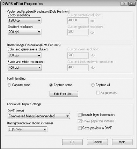
When you finish specifying the properties for the DWF file format, click OK. If you see a message asking whether you to apply the changes for the current plot only (which creates an override of the configuration file but doesn't change it) or to save the changes to the file (which changes the configuration file, although you can always change it back), respond as desired.
Note
The drawing used in the following exercise on creating a 2D DWF file, ab28-01.dwg, is in the Results folder on the DVD. If you did the previous exercise, you also have this file in your AutoCAD Bible folder.
STEPS: Creating a 2D DWF File
If you did the previous exercise, use
ab28-01.dwg. If not, open it from theResultsfolder on the DVD and save it to yourAutoCAD Biblefolder. Although this drawing is a 3D drawing, you can make a 2D DWF file from it, especially if you want to preserve the hyperlinks.Close any other drawings that you may have open. Choose Output tab
Choose
ab28-01-Modeland click Remove Sheets.In the Publish To drop-down list, choose DWF. Click Publish to create the DWF file.
In the Specify DWF File dialog box, enter
ab28-02.dwfandAutoCAD Biblefor the file location. Click Select.A Publish - Save Sheet List dialog box opens and asks whether you want to save the current list of sheets. Click No. If you see the Processing Background Job message telling you that your job is processing in the background, click Close.
You use the PUBLISH command to create 3D DWF or DWFx files in the same way that you create 2D DWF or DWFx files, as explained previously in this chapter. (AutoCAD LT doesn't contain this feature.) You don't need to specify that the file is a 3D drawing. You can also use the 3DDWF command to create a 3D DWF or DWFx file and immediately open it in the Autodesk Design Review. This method has fewer options but is quicker. You can also choose Application Button
Either way, a dialog box opens where you can specify the name and location of the file. To set a few options, choose Tools
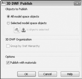
Choose whether you want to publish all objects or just selected objects, and how you want to organize xrefs in the drawing — either along with other objects or by their xref hierarchy. You can also choose to publish materials that you've attached to objects or layers. Then click OK to return to the Export 3D DWF dialog box. Specify a location and name for the DWF or DWFx file and click Save. A message appears asking whether you want to view the file. Click Yes to open the file in Autodesk Design Review.
The 3D DWF and DWFx files (for AutoCAD only) are similar to 2D DWF and DWFx files, but the following items are not displayed:
Images and other inserted (OLE) objects
Hyperlinks
Bold and italic fonts
Gradients
Certain rendering features, such as lights, shadows, and certain types of materials
Rays and xlines
Named views and cameras
Hidden edges
The Publish to Web feature creates HTML pages that display your drawings in DWFx, DWF, JPEG, or PNG format. Through the use of templates, you can upload drawings without getting involved in Web-design issues.
To publish drawings to the Web, first prepare your drawings and decide how many you want to publish. Then follow these steps:
Type publishtoweb

Choose to create a new Web page or edit an existing one. Then click Next.
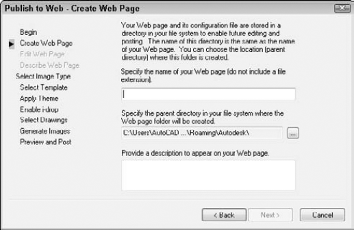
On the Create Web Page screen, shown in Figure 28.9, type a filename for the Web page. (This action creates a folder with this name and places all the files for the Web page in the folder.) Then click the ellipsis button (...) to navigate to where you want to create this file. If you already store Web page files on your system, you can use the same location. Finally, add a description that will appear on the Web page. Click Next.
On the Select Image Type screen, choose the type of image that you want to create, whether DWFx, DWF, JPEG, or PNG. As you choose each type from the drop-down list, a description appears on the screen. For JPEG and PNG, also click the image size that will appear on the Web page. Click Next.
On the Select Template screen, choose a template that structures your Web page, and click Next. You have four choices:
Array of Thumbnails. Creates a set of thumbnail images. Clicking any image displays a larger image.
Array plus Summary. Creates a set of thumbnail images. Adds information from the Summary tab of the Drawing Properties dialog box, displayed when the mouse cursor is over a thumbnail. (Choose Application Button
List of Drawings. Creates a list of drawings and a frame displaying a drawing image. Users select a drawing from the list to update the image in the frame.
List plus Summary. Creates a list of drawings, an image frame, and summary information from the Summary tab of the Drawing Properties dialog box, displayed when the mouse cursor is over a thumbnail. (Choose Application Button
On the Apply Theme screen, choose one of the preset themes that control colors and fonts on your Web page. You see an example in the preview pane. Click Next.
On the Enable i-drop screen, choose whether you want to create an i-drop Web page so that users can drag actual drawings from the Web page into a drawing. Click Next.
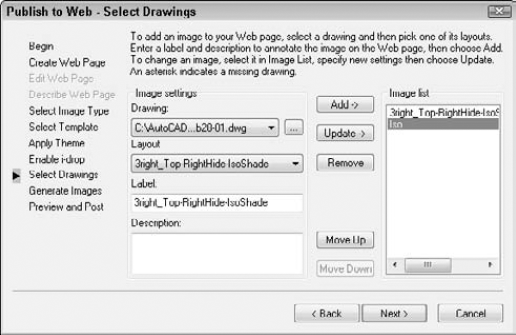
On the Select Drawings screen, shown in Figure 28.10, choose the drawings that you want to publish. If the drawing is open, you can select it from the Drawing drop-down list. Select each drawing, choose a layout (or model) from the Layout drop-down list, type a label, and type a description to appear on the Web page. Then click Add. (If the drawing is not open, click the ellipsis button, navigate to the drawing, and click Open. Enter a label and description and then click Add.) Click Next.
On the Generate Images screen, choose to regenerate either all images or only those that have changes. (There is no difference if you're creating a new Web page.) Click Next and wait for the plotting process to complete.
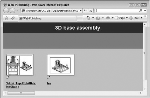
On the Preview and Post screen, click Preview to preview what the Web page will look like. Your Web browser opens and displays a fully functional Web page, including links, if any. Figure 28.11 shows an example.
Click Post to post your new Web page. The Posting Web dialog box opens, which is like the Save As dialog box. In the Save In drop-down list, choose the desired location. To use FTP to post directly to a server, choose FTP locations or choose FTP from the Places list. (If you're saving to an intranet, you'll choose a location designated by your network administrator.) Double-click the FTP location and wait until you see the folder structure of your Web site. If you want, double-click one of the folders to save there. (The Publish to Web process creates a number of files. You probably don't want them all in the root of your Web site.) Click Save. You should see a File Upload dialog box showing the progress of the file transfer. If everything goes well, you'll see a success message that posting has been successfully completed.
Note
Remember to also upload any files that you have hyperlinked to in your drawing.
If you want, click Send Email to notify people of the URL to the new Web page.
To find your new page, look for a file named
acwebpublish.htm.
You can always upload the files by yourself, using your own FTP program or whatever other means you usually use to post to the Web site.
You don't need to use the Publish to Web Wizard to place DWF or DWFx files on a Web site. You can upload 2D and 3D DWF and DWFx files directly, and give people the URL or place a link to them on another page. You can also create JPG or PNG images on your own, as I explained in Chapter 27, and use them to display an image of the DWF or DWFx file.
You can edit your Web page — for example, you can delete existing drawings and add new ones. Start the Publish to Web command and choose Edit Existing Web Page on the first screen. Click Next and choose the Web page that you want to edit by choosing a PTW (Publish to Web) file. Click Next again. From this point on, you can change any existing information.
On the Select Drawings screen, click Update to update a drawing that has changed since the last time that you created the Web page. Click Remove to remove a drawing. To add a new drawing, follow the same procedures described in the previous section.
To change the order of the drawings, select a drawing from the list and click Move Up or Move Down until you have the results that you want. Continue through the wizard and re-post your drawings.
The final step is to view the drawings. If you use the Publish to Web Wizard to create JPEG or PNG drawings, you simply view them like any other image. However, DWF and DWFx drawings, whether viewed locally on a computer or from a Web site, can be panned and zoomed and offer other viewing options as well. To view a DWF drawing, you need Autodesk Design Review. You can view DWFx files in Autodesk Design Review or Microsoft XPS Viewer. Autodesk Design Review is free and is automatically installed when you install AutoCAD or AutoCAD LT. It is also available as a free download from the Autodesk Web site at www.autodesk.com/designreview. If you are using Windows Vista, the XPS Viewer comes installed, but if you are using Windows XP, you can download and install it for free. To learn more about the XPS viewer, you can visit the Microsoft Web site at www.microsoft.com/xps.
The XPS Viewer offers only basic viewing features, such as scrolling and changing the zoom percentage used. To view 3D DWFx files and the metadata saved with a DWFx file, you need Autodesk Design Review; you also get better viewing tools with Autodesk Design Review.
Autodesk Design Review can function in two ways:
As a stand-alone reader, it opens like any other program. (You can generally find it by choosing Start
As an ActiveX component, Autodesk Design Review functions within Microsoft Internet Explorer. Use the reader within Internet Explorer when you've posted DWF or DWFx files on a Web site. When you enter the URL in the browser, the DWF file appears. (The ActiveX doesn't work in the Firefox Web browser. Instead, the browser offers to download the file or open it, using Autodesk Design Review.)
If you send DWF or DWFx files to clients or colleagues, you can send them the link to the Install file for Autodesk Design Review as well.
If you've given a DWF or DWFx file a password, a dialog box opens, requesting the password before the DWF or DWFx file is displayed.
To view any sheet in the DWF or DWFx file, choose it from the list at the left, or use the Next and Previous buttons on the viewer's toolbar. Choose the Views tab on the right side to display any named views that were saved with the drawing. You can use saved views to help a customer focus on certain details and provide information about the views that you saved.
By default, layer information is not included in the DWF or DWFx format. As explained earlier in this chapter, you can include layer information if you want. If the DWF or DWFx file includes layer information, viewers can choose the Layers tab on the right side, where they can choose to click the On or Off toggle next to a layer.
Viewers have complete freedom to pan and zoom however they want. Note that if you're sending a DWF or DWFx file to a client who doesn't use AutoCAD or AutoCAD LT, the controls may not be obvious, so you may need to provide an explanation. The controls are as follows:
Fit to Window is equivalent to a Zoom Extents. The button looks like the Zoom Extents button.
Zoom Rectangle does a Zoom Window.
For 3D DWF and DWFx files only, the Orbit option functions somewhat like the 3D Orbit feature. (See Chapter 22 for an explanation of 3D Orbit.) Drag to tumble the model in any direction, as shown in Figure 28.12. Press Ctrl as you drag to constrain the tumbling to the vertical direction. Press Shift as you drag to tumble only horizontally. Press Ctrl and Shift together as you drag to constrain the view to rolling.
Tip
The Orbit option works better if you first use the Zoom Rectangle option. Otherwise, the model tends to disappear from view as you drag.
Zoom enables you to zoom. Drag up to zoom in, and drag down to zoom out.
Pan enables you to pan. Drag in any direction to pan in that direction.
A mouse with an IntelliMouse wheel works just as it would in AutoCAD or AutoCAD LT. Zoom in by scrolling forward, and zoom out by scrolling backward. Press the wheel and drag to pan.
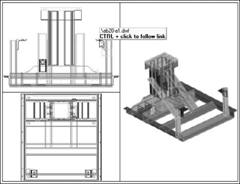
If the DWF or DWFx file has hyperlinks, when your cursor passes over a URL area, you can click to follow the link, as shown in Figure 28.13.
You can print/plot drawings from Autodesk Design Review. The print options are somewhat like those in Microsoft Word because they take into account the fact that a DWF or DWFx file can have many pages. Click the Print button on the Quick Access toolbar to open the Print dialog box, as shown in Figure 28.14.
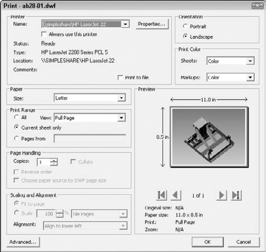
The Print dialog box offers the following features:
Printer. In the Printer section, choose the printer or plotter that you want to use. Click Properties to specify how the printer/plotter functions. The features depend on the device that you choose. You can also select the Print to File check box to print to a file. Check Always Use This Printer if you typically use a printer other than the default Windows printer when using Autodesk Design Review.
Paper. Choose the page size from the drop-down list. The available paper sizes vary, depending on your printer or plotter.
Print Range. You can choose to print all pages, or you can specify the pages. You can also choose Full Page or Current View from the View drop-down list. (Remember that 3D DWF and 3D DWFx files can only have one page.)
Page Handling. Choose the number of copies you want to print and whether you want to collate them.
Scaling and Alignment. You can fit to the page or specify a scale. If you scale, you can tile or clip the pages. If you clip them, you can align to one corner of the paper or center the drawing.
Orientation. Choose Portrait or Landscape.
Color Setting. You can print in color, black and white (2D DWF and DWFx files only), or grayscale.
Advanced. Click Advanced to convert the data that is selected for printing into a bitmap; this can help to speed up printing, but it may use more memory. This option only affects 2D DWF and DWFx files.
The Preview pane lets you visualize what the output will look like. If you choose All or multiple pages in the Print Range section, you can use the arrows to scroll through each page in a multipage DWF file.
Click OK to print. If you choose a size that doesn't fit on one sheet of paper, you see a message saying that the drawing may print across several pages.
Note
The file used in the following exercise on viewing a DWF drawing, ab28-02.dwf, is in the Results folder of the DVD.
STEPS: Viewing a DWF Drawing
If you didn't do the exercise on creating a 2D DWF file, copy
ab28-02.dwffrom the DVD to yourAutoCAD Biblefolder. Open Windows Explorer and navigate toab28-02.dwf. Double-click the file to open it in Autodesk Design Review.Note
If the DWF file were on a Web site, you would view it by typing the URL in your browser.
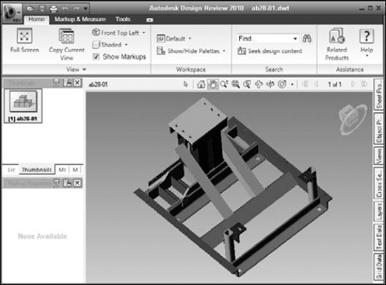
Autodesk Design Review opens automatically and displays the DWF file that was created in the previous exercise. From the Contents item on the left pane of the Autodesk Design Review, choose the second sheet, labeled
[2]ab28-01-Iso (11.0 × 8.5 in), as shown in Figure 28.15.Right-click in the drawing to open the shortcut menu. Choose Zoom Rectangle. Drag a window to zoom in. Choose Pan from the shortcut menu, and pan to the left. Choose Fit in Window from the shortcut menu to return to the previous view.
To print the drawing to the system printer, click Print on the Quick Access toolbar. In the Print dialog box, click the All option in the Print Range section. Click OK.
Close Autodesk Design Review.
In this chapter, you discovered how to integrate your drawings with the Internet. You read about the following:
Faxing, e-mailing, and eTransmitting drawings
Opening drawings from anywhere on the Internet
Creating hyperlinks in your drawings
Using the PUBLISH command to create DWF and DWFx files
Creating 3D DWF and 3D DWF files
Using the Publish to Web Wizard to create Web pages with DWFx, DWF, JPEG, or PNG images
Utilizing Autodesk Design Review to view DWF and DWFx files
This chapter ends Part V, "Organizing and Managing Drawings." Part VI, "Customizing AutoCAD and AutoCAD LT," shows you the inner workings of AutoCAD and AutoCAD LT so that you can work in the way that best suits your needs. Chapter 29 explains how to create customized command shortcuts and toolbars.